
Product Manual


Design and function
CAP-834 9
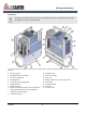
1.2 Brief description
The fresh air supplied by the cooling air fan is fil-
tered through the intake filter. The air flows through
the intake valve into the compressor airend, where it
is compressed together with the injected oil to the
final pressure. The oil is largely separated from the
compressed air in the oil separator tank. The air/oil
separator removes the remaining oil from the com-
pressed air. The compressed air then flows through
the minimum pressure and non-return valve into the
air after-cooler and is cooled down before it leaves
the screw compressor via the discharge port.
The oil is separated from the compressed air in the
oil separator tank and the air/oil separator and flows
to the oil cooler. The oil temperature thermostat
adds the cooled oil to the hot oil via the oil cooler
bypass according to the set point temperature. Fi-
nally, the oil filter cleans the oil before it is injected
into the compressor airend again.
1.3 Assembly description
1.3.1 Controller
Controller variants
For detailed information about the
controller installed, consult the
separate
Controller documentation.
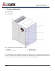
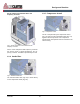
1.3.2 Enclosure panels
Fig. 3: Enclosure panels
Only qualified personnel may remove the enclosure
doors (Fig. 3/1) with the included special wrench.
Enclosure doors are a part of the electric shock
protection and reduce the sound level emitted by
the unit.
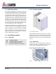
1.3.3 Drive unit
Various drive units are installed in the screw com-
pressors. They differ in construction, their technical
data and their functional principle as follows:
Screw compressor with V-belt drive
Fig. 4: Screw compressor with V-belt drive