AN706-00040-2v0-E FM3 Family 32-BIT MICROCONTROLLER FM3 family Application Note Simple AV System Board User Manual ARM and Cortex-M3 are the trademarks of ARM Limited in the EU and other countries.
AN706-00040-2v0-E All Rights Reserved. The contents of this document are subject to change without notice. Customers are advised to consult with FUJITSU sales representatives before ordering.
AN706-00040-2v0-E Revision History Rev Date Remark 1.0 Aug.23,2011 First Edition 2.0 Feb.
AN706-00040-2v0-E Table of Contents Revision History .......................................................................................................................2 Table of Contents .....................................................................................................................3 Target products ........................................................................................................................6 1 INTRODUCTION ..............................................
AN706-00040-2v0-E 7.1.6.1 Power switch ........................................................................................... 40 7.1.6.2 Key Input Switch ...................................................................................... 41 7.1.6.3 Reset Switch............................................................................................ 41 7.1.7 7.1.7.1 LCD Module with Touch Panel ................................................................ 42 7.1.7.2 Power LED ........
AN706-00040-2v0-E 7.2.7.2 7.2.8 AAC ......................................................................................................... 78 Operation Flow ............................................................................................... 82 7.2.8.1 Main Processing Function ....................................................................... 82 7.2.8.2 USB Task Processing Function ............................................................... 83 7.2.8.
AN706-00040-2v0-E Target products This application note is described about below products; (TYPE0) Series Product Number (not included Package suffix) MB9B500B MB9BF504NB,MB9BF505NB,MB9BF506NB MB9BF504RB,MB9BF505RB,MB9BF506RB MB9B300B MB9BF304NB,MB9BF305NB,MB9BF306NB MB9BF304RB,MB9BF305RB,MB9BF306RB 6
AN706-00040-2v0-E 1 INTRODUCTION This user manual contains specifications and information on how to use the simple AV system board. 2 OVERVIEW OF SIMPLE AV SYSTEM BOARD The simple AV system board plays the following 2 types of music media files and performs 1 type of image output. Music media files are however not played simultaneously; The format of played music file is set in accordance with compile options.
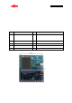
AN706-00040-2v0-E 3 PREPARATIONS 3.1 System Items A list of system items of the simple AV system board is given in Table 1, a photograph the external appearance of the AV system board is shown in Figure 2, a photograph the external appearance of ICE is shown in Figure 3, a photograph of the external appearance of the USB memory is shown in Figure 4 and a photograph the external appearance of the USB cable is shown in Figure 5. Table 1 List of System Items No. Name Pcs.
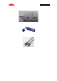
AN706-00040-2v0-E Figure 3 ICE Figure 4 USB memory Figure 5 USB cable 9
AN706-00040-2v0-E 3.2 Equipment Other than System Item Required A list of equipment other than system items required is given in Table 2, and equipment used as need is given in Table 3. Table 2 Equipment other than system items required No. 1 Name pcs. PC 1 Specifications / Remarks Use USB host port for power supply. If using ICE, use USB host port. Table 3 List of Equipment Used as Needed No. 1 Name Earphones or speakers pcs.
AN706-00040-2v0-E 3.3 Board Appearance A photograph of the external appearance of the simple AV system board is shown in Figure 6.
AN706-00040-2v0-E 3.4 Power Supply Method USB bus power of the PC is used as the power supply for the simple AV system board. Connect the Type A side of the USB cable (with Type A - Type B connector) to the USB port of the PC and connect the Type B side to the USB power supply connector of the simple AV system board. Press down the power switch with the USB cable connected. The power supply switch is self-locking and stays depressed while the power is on.
AN706-00040-2v0-E 4 PROGRAM EXECUTION METHOD 4.1 Program Execution Using Debugger 4.1.1 Activation of KEIL Integrated Development Environment Double-clicking “AV_demo.uvproj” inside the Project folder activates the KEIL integrated development environment and opens the simple AV system project.
AN706-00040-2v0-E In the case of MP3, set “MUSIC_MP3” for “Define” of the “C/C++” and “Asm” tabs of the option screen; in the case of AAC, set “MUSIC_AAC”.
AN706-00040-2v0-E (2) Program Build プログラムをリビルド Rebuilds program. プログラムをビルド Builds program. Figure 11 Simple AV System Build Click the location shown in Figure 11 to build or rebuild the program. After successfully building or rebuilding, the sample program can be exported to the microcontroller.
AN706-00040-2v0-E 4.1.2 Start of Sample Program Export and Debug (1) ICE Connection The equipment connection diagram for exporting the program to the microcontroller is shown in Figure 12. The PC and simple AV system board are connected via ICE. Figure 12 Equipment Connections for Exporting Program (2) Exporting the Program to the Microcontroller Click the location shown in Figure 13 to export the program to the microcontroller. マイコンへプログラムを書き込み Writes program in microcontroller.
AN706-00040-2v0-E (3) Debug Activation Click the location shown in Figure 14 and activate the debugger. Debugging can then be started. Starts debug.
AN706-00040-2v0-E 4.1.3 Program Execution Using Debugger When the debugger is activated, the screen appears as shown in Figure 15. Press “Execute” to start executing the program. Execute Figure 15 Screen When Debugger is Activated For other debugger operations, see help. 4.2 Standalone Program Execution When the program is exported and debugging is completed by the procedure given in “4.
AN706-00040-2v0-E 5 SUPPORTED MEDIA 5.1 Formats that can be Used for USB Memory The USB memory formats that can be used by the file system are given in Table 4. If using a file system (middleware), a separate contract is required. Table 4 Recognition Media Capacity and Applicable Formats No. Recognition Media Applicable Formats Remarks Capacity 1 Max. 256Mbyte FAT16 / FAT32 2 256M to 8Gbyte FAT32 5.
AN706-00040-2v0-E 5.3 Image Data The items of image data supported by the sample program are given in Table 6. If using a JPEG encoder/decoder (middleware), a contract is required. Table 6 Image Data Supported by the Sample Program No. Item 1 File format 2 File name 3 Resolution Description Remarks JPEG “picture1.jpg” to “picture5.jpg” “select.
AN706-00040-2v0-E 6 OPERATION METHOD Touch Operation Area Power Switch Speaker Connector USB Connector for Power Supply Select your favorite music! USB Memory Connector Selection Previous Switch Selection Next Switch Reset Switch Selection Indicator LED Play/Stop Switch Figure 16 Operation Explanation Diagram 6.1 MP3 File Play (1) From Preparation to Power On ① Audio data (music1.mp3 to music5.mp3) and image data (picture1.jpg to picture5.jpg, select.
AN706-00040-2v0-E (2) Song Selection Operation Pressing the song selection next switch selects audio file in the following order. music1.mp3 => music2.mp3 => ... => music5.mp3 If the next switch is pressed while music5.mp3 is selected, music5.mp3 is then selected. Pressing the song selection previous switch selects audio file in the following order. music5.mp3 => music4.mp3 => ... => music1.mp3 If the next switch is pressed while music1.mp3 is selected, music1.mp3 is then selected.
AN706-00040-2v0-E (3) Play Start Operation While music is not yet played, the selected music can be played by the following operation. ① Press down the Play/Stop switch. Play/Stop Switch Figure 18 Play Start Operation by Play/Stop Switch ② Touch the thumbnail on the touch panel (LCD) (MP3). (picture1.jpg to picture5.jpg corresponds to music1.mp3 to music5.mp3) Touch the touch operation area image with your finger.
AN706-00040-2v0-E Figure 20 LCD Display While Playing 24
AN706-00040-2v0-E (4) Play Stop Operation While music is playing, it can be stopped by the following operation. ① Press the Play/Stop switch. Play/Stop Switch Figure 21 Play Stop Operation by Play/Stop Switch ② Touch the touch panel. When you touch the enlarged image with your finger, the music stops playing. Touch Operation Area Figure 22 Play Stop Operation by Touch Panel When music is stopped the image simultaneously switches the thumbnail display.
AN706-00040-2v0-E Select your favorite music! Figure 23 Thumbnail Display 26
AN706-00040-2v0-E 6.2 AAC File Play (1) From Preparation to Power On Audio data (music1.aac to music5.aac) is contained in the root directory of the USB memory. Insert USB memory in USB memory connector of simple AV system board. Connect earphones or speakers to the speaker connector. Connect USB cable to the USB connector for power supply. Press power switch (power on). (2) Song Selection Operation Pressing the song selection next button selects audio file in the following order. music1.aac => music2.
AN706-00040-2v0-E (3) Play Start Operation While music is being played, the selected music can be played by the following operation. ・ Press down the Play/Stop switch. Play/Stop Switch Figure 25 Play Start Operation by Play/Stop Switch (4) Play Stop Operation While music is playing, it can be stopped by the following operation. ・ Press the Play/Stop switch.
AN706-00040-2v0-E 7 SPECIFICATIONS 7.1 Hardware 7.1.1 General Specifications General specifications of the simple AV system board are given in Table 7. Table 7 General Specifications No. Item Description 1 Microcontroller MB9BF506R(Fujitsu Semiconductor) 2 Power supply USB bus power (+5V) Remarks Does not include 3 Current consumption 300mA(typ.) external connected equipment.
AN706-00040-2v0-E 7.1.2 Hardware Block Diagram The hardware block diagram is shown in Figure 27. LCD Board Speaker Jack MB9BF506R DAC Counter CLK SCK SCK X‟tal CSIO 27MHz Clock Generator OSC Touch Panel Microcontroller Board JTAG JTAG Interface ICE Touch Panel Driver LED Backlight Driver GPIO Switch LCD LCD Driver 5V USB Connector External Bus 5V USB Host LDO USB Host Interface 3.3V LED 3.
AN706-00040-2v0-E 7.1.3 Main Components A list of main components is given in Figure 8. Figure 8 Main Components of Simple AV System Board No. Part Number pcs.
AN706-00040-2v0-E 7.1.4 Microcontroller 7.1.4.1 Pin Connection A photograph of the external appearance of the microcontroller is shown in Figure 28 and a list of pin connections is given in Table 9. Microcontroller(MB9BF506R) Figure 28 Photograph of Microcontroller External Appearance Table 9 List of Microcontroller Pin Connections Pin No. Pin Name (Use Connection Destination I/O Function) 01 VCC +3.
AN706-00040-2v0-E Pin Pin Name (Use No. Connection Destination I/O Function) 15 MDATA07 LCD controller (D7) I/O 16 (Not used) ― ― 17 (Not used) ― ― 18 (Not used) ― ― 19 (Not used) ― ― 20 P36 Touch panel controller (xCS) O INT10_1 Touch panel controller 21 I (xPENIRQ) 22 (Not used) ― ― 23 (Not used) ― ― 24 (Not used) ― ― 25 (Not used) ― ― 26 (Not used) ― ― 27 (Not used) ― ― 28 (Not used) ― ― 29 (Not used) ― ― 30 VSS GND ― 31 VCC +3.
AN706-00040-2v0-E Pin No. Pin Name (Use Connection Destination I/O Remarks Function) 46 (Not used) ― ― 47 (Not used) ― ― 48 (Not used) ― ― 49 (Not used) ― ― 50 (Not used) ― ― 51 (Not used) ― ― 52 (Not used) ― ― 53 (Not used) ― ― 54 (Not used) ― ― 55 (Not used) ― ― 56 MD1 GND ― 57 MD0 Jumper pin ― 58 X0 Crystal oscillator (4MHz) I 59 X1 Crystal oscillator (4MHz) I/O 60 VSS GND ― 61 VCC +3.
AN706-00040-2v0-E Pin No. Pin Name (Use Connection Destination I/O Function) 77 MDATA12 LCD controller (D12) I/O 78 MDATA13 LCD controller (D13) I/O 79 MDATA14 LCD controller (D14) I/O 80 MDATA15 LCD controller (D15) I/O 81 (Not used) ― ― 82 (Not used) ― ― 83 (Not used) ― ― 84 (Not used) ― ― 85 (Not used) ― ― 86 (Not used) ― ― 87 (Not used) ― ― 88 (Not used) ― ― 89 (Not used) ― ― 90 VSS GND ― 91 VCC +3.3V power supply ― 92 TRSTX N.C.
AN706-00040-2v0-E Pin No. Pin Name (Use Connection Destination I/O Function) 107 (Not used) ― ― 108 (Not used) ― ― 109 (Not used) ― ― 110 (Not used) ― ― DA converter (SCK), 111 SCK5_1 Binary Counter I (Q2[8 divisions output]) 112 SOT5_1 DA converter (SDIN) O 113 P63 Clock Generator(S0) O 114 (Not used) ― ― 115 P61 Clock Generator(S1) O 116 (Not used) ― ― 117 USBVCC +3.
AN706-00040-2v0-E 7.1.4.2 Microcontroller Mode Switch and Function Switch The microcontroller has the following two modes, which can be switched by external jumper socket. (1) Serial writer mode (2) User mode This section contains an overview of the two modes and a description of the setting method. (1) Serial writer mode [Overview] Built-in flash serial programming of the microcontroller mounted on the microcontroller board can be carried out.
AN706-00040-2v0-E (2) User Mode [Overview] Mode that activates the internal ROM (flash) of the microcontroller mounted in the microcontroller. Operation starts when the CPU obtains reset vector from the flash memory. Setting the MD0 pin of the microcontroller to “L” level switches to this mode. [Setting Method] Insert the jumper for switching modes of the microcontroller in the silk notation “MD0L” side.
AN706-00040-2v0-E 7.1.4.3 USB Interface Function Switching The microcontroller has the following two USB interface functions, which can be switched by external jumper socket. (1) USB Host Interface Function (2) USB Function Interface Function This section contains an overview of the two interface functions and a description of the setting method. (1) USB Host Interface Function (Set when User Mode is Selected) [Overview] The USB interface of the microcontroller is used as the host.
AN706-00040-2v0-E 7.1.5 DA Converter The LCD board is equipped with a DA converter for I2S conversion. The external appearance and connection diagram of the DA converter are shown in Figure 33. DA Converter Microcontroller DA Converter Pin No.103:SOT4_0 Pin No.4:LRCK Pin No.104:SCK4_0 Pin No.3:MCLK Pin No.111:SCK5_1 Pin No.112:SOT5_1 Pin No.2:SDIN Pin No.115:P61 Pin No.113:P63 Clock Generator 11.2896MHz or 12.288MHz Pin No.5:SCLK Pin No.5:CLK Pin No.3:S0 Pin No.6:S1 Binary Counter 1.
AN706-00040-2v0-E 7.1.6.2 Key Input Switch The LCD board is equipped with a power switch. The external appearance and connection diagram of the key input switch are shown in Figure 35. +3.3V Selection Prev Switch Microcontroller Selection Next Switch Selection Prev Switch (P68) Pin No.108:P68 Play/Stop Switch Selection Next Switch (P71) Pin No.52:P71 Pressed Down: L Not Pressed Down: H Play/Stop Switch (P73) Pin No.54:P73 Figure 35 Key Input Switch External Appearance and Connection Diagram 7.1.
AN706-00040-2v0-E 7.1.7 Indicator 7.1.7.1 LCD Module with Touch Panel The LCD board is equipped with an LCD module with touch panel. The external appearance of the LCD module with touch panel is shown in Figure 37 and the specifications of the LCD module with touch panel are given in Figure 10. For connection of microcontroller and LCD module with touch panel, see Table 9.
AN706-00040-2v0-E 7.1.7.2 Power LED The microcontroller board is equipped with a power LED that indicates power supply status. The external appearance of the power LED is shown in Figure 38 and the specifications are given in Table 11. Power LED Figure 38 Power LED external appearance Table 11 Power LED Specifications No.
AN706-00040-2v0-E 7.1.7.3 Selection Indicator LED The microcontroller board is equipped with a selection indicator LED that indicates selection status. The external appearance and connection diagram of the selection indicator LED are shown in Figure 39 and the selection indicator LED specifications are given in Table 12. +3.3V Microcontroller music5.xxx Pin No.22:P38 Pin No.23:P39 Pin No.24:P3A Selection Indicator LED Pin No.25:P3B Pin No.
AN706-00040-2v0-E 7.1.8 External Interface 7.1.8.1 Power Supply Interface The LCD board is equipped with a USB connector that functions as a power supply interface. Power is supplied by connecting the USB cable to the USB connector for power supply. The external appearance of the USB connector for power supply is shown in Figure 40. The USB connector for power supply uses a conventional USB-B Type connector, but the USB signal line is not connected. Only VBUS and GND are connected.
AN706-00040-2v0-E 7.1.8.3 USB Interface The microcontroller board is equipped with a USB memory connector that functions as a USB interface. The external appearance of the USB memory connector is shown in Figure 42 and the USB memory connector specifications are given in Table 13. USB Memory Connector Figure 42 USB Memory Connector External Appearance Table 13 USB Memory Connector Specifications Pin No. Microcontroller connection destination I/O (*) Pin No.
AN706-00040-2v0-E 7.1.8.4 JTAG Interface The microcontroller board is equipped with a JTAG interface connector for software debugging by JTAG interface. The external appearance of the JTAG interface connector is shown in Figure 43 and the pin assignment is given in Table 14. JTAG Interface Connector 10 9 2 1 Figure 43 JTAG Interface Connector External Appearance Table 14 JTAG Interface Connector Pin Assignment Microcontroller I/O connection destination (*) Pin No. Pin No. Signal Name ― +3.
AN706-00040-2v0-E 7.1.8.5 ETM Interface The microcontroller board is equipped with an ETM interface connector for software debugging by ETM interface. The external appearance of the ETM interface connector is shown in Figure 44 and the pin assignment is given in Table 15. ETM Interface Connector 20 19 2 1 Figure 44 ETM Interface Connector External Appearance Table 15 ETM Interface Connector Pin Assignment Microcontroller connection I/O destination (*) Pin No. Pin No. Signal Name ― +3.
AN706-00040-2v0-E 7.2 Software 7.2.1 Software Block Diagram The software block diagram is shown in Figure 45.
AN706-00040-2v0-E 7.2.2 Software Library (1) File System Name Multi Device File Access Library V03L01 (object for small MCU, Evaluation) Overview File system library for embedded system (abbreviated as MDF). Used when you want to handle data a directory created by target devices by PC. Facilitates data transfer between PC and devices because multi device data can be managed by the same file and directory format used by the PC.
AN706-00040-2v0-E 7.2.3 System Specifications 7.2.3.1 Microcontroller System Specifications Microcontroller system specifications are given in Table 16. Table 16 Microcontroller System Specifications Item Description Operation CPU:80MHz Clock APB1 to 3:40MHz ROM(FLASH) 113.0Kbyte (*1) Remarks High-speed PLL oscillation Internal 20 multiplier MP3 Vector section: 248 bytes Program section: 112.7 Kbytes 152.6 Kbytes AAC Vector section: 248 bytes Program section: 152.4 Kbytes RAM (*1) 64.
AN706-00040-2v0-E 7.2.3.2 Memory Map The memory maps for ROM (flash) and RAM are shown in Figure 46.
AN706-00040-2v0-E 7.2.3.3 MFS System Specifications MFS system specifications are given in Table 17. Table 17 MFS System Specifications Channel No.
AN706-00040-2v0-E 7.2.3.5 Interrupt System Specifications Interrupt system specifications are given in Table 19. Table 19 Interrupt System Specifications Interrupt Factor Vector Function Remarks Number Reset Reset_Handler #01 - Base timer ch. 2 BTIM_IRQHandler #47 Processes an interrupt by 1ms interrupt cycle. USB host (each USB_EP0_STA_IRQHandler #50 status) interrupt DMAC ch. Processes an interrupt for USB host interrupt.
AN706-00040-2v0-E 7.2.4 API Specifications This chapter gives I2S driver API used for audio playback processing in addition to API used for application layer. I2S driver API is also described in the application notes for simple AV system solution. For more information, see the notes. 7.2.4.1 Audio Playback API Function void AUDIO_Init(void) Overview Audio playback processing initialization function Invoked before entering the main loop (see “7.2.8.1 Main Processing Function”).
AN706-00040-2v0-E Function void AUDIO_PlayTask(void) Overview Audio play processing main function Invoked during main loop (see “7.2.8.1 Main Processing Function”). Parameter None Return None value 7.2.4.2 Image Display API Function void IMAGE_Init(void) Overview Image display processing initialization function Invoked before entering the main loop (see “7.2.8.1 Main Processing Function”).
AN706-00040-2v0-E Function uint8_t IMAGE_Show( const uint8_t *FileName, uint8_t AreaID, uint16_t Color) Overview Image display control processing function Parameter FileName Filename read from USB memory AreaID LCD display area No.
AN706-00040-2v0-E (*) LCD display area corresponds as follows.
AN706-00040-2v0-E 7.2.4.3 LED Control API Function void LED_Init (void) Overview LED control processing initialization function Invoked before entering the main loop (see “7.2.8.1 Main Processing Function”). Parameter None Return None value Function STATUS LED_Set(uint16_t IdCh, uint8_t LEDStatus) Overview LED control processing function Turns specified LED on or off.
AN706-00040-2v0-E 7.2.4.4 Switch Detection API Function void SW_Init (void) Overview Switch detection processing initialization function Invoked before entering the main loop (see “7.2.8.1 Main Processing Function”). Parameter None Return None value Function STATUS SW_GetStatus(uint8_t ButtonId, uint8_t *pStatus) Overview Switch status acquisition function Parameter ButtonId Switch No.
AN706-00040-2v0-E 7.2.4.5 Timer Control Driver API Function void TIMER_Init(void) Overview Initialization function for timer control driver Invoked before entering the main loop (see “7.2.8.1 Main Processing Function”). Parameter None Return None value Function STATUS TIMER_Start(uint8_t IdCh) Overview Timer start function Invoked before entering the main loop and after TIMER_Init invocation (see “7.2.8.1 Main Processing Function”).
AN706-00040-2v0-E 7.2.4.6 Touch Panel Control Driver API Function STATUS TOUCH_Init(void) Overview Initialization function for touch panel control driver Invoked before entering the main loop (see “7.2.8.1 Main Processing Function”).
AN706-00040-2v0-E 7.2.4.7 I2S Driver API Function void I2S_Init (void) Overview Initializes I2S driver. Sets MFS initial settings (CSIO settings) and DMAC initial settings. Parameter None Return None value Function STATUS I2S_Start (uint8 t audio sample rate) Overview Starts I2S operation. Sets data for DMAC and activates CSIO. Be sure to initialize by I2S_Init function before function is invoked. Parameter Audio sample rate Sampling rate AUDIO_SAMPLE_44100 44.
AN706-00040-2v0-E 7.2.5 Operation Limit The following limitations apply to operation of the sample program used by the simple AV system. ◆Concerning assembly of MP3 and AAC decoder The MP3 and AAC decoders cannot conduct processing simultaneously because the built-in RAM size is insufficient. ◆Concerning JPEG file processing for AAC decoder assembly If an AAC decoder is assembled, JPEG file decode processing cannot be conducted because the built-in RAM size is insufficient.
AN706-00040-2v0-E 7.2.6 Operation Flow of Entire Application 7.2.6.1 MP3 (1) The application operation flow with audio data playback stopped is as follows. ① USB MSC device connection/disconnection judgment is executed in the main loop. ② If a USB memory is connected, after reading the JPEG files from the USB memory and displaying the images for selection, switch pressing detection and touch panel detection are conducted.
AN706-00040-2v0-E Timer interrupt(ch.2)(1ms) USB-MSC device connection/ disconnection judgement Media files select.jpg picture1.jpg picture2.jpg picture3.jpg picture4.jpg picture5.jpg No Switch detection module Was media connected? Play/Stop switch Yes JPEG File Read all JPEG files and display images for selection on LCD Switch chattering processing Selection previous switch Selection next switch Switch state Switch press detection music1.mp3 No Was the Play/Stop switch pressed? music2.
AN706-00040-2v0-E (2) The application operation flow with audio data playback in progress is as follows. ① USB MSC device connection/disconnection judgment is executed in the main loop. ② If the USB memory has been removed, stop playback, close the opened MP3 file, quit the file system and operation shifts to initialization status. ③ If the USB memory is connected, play/stop switch press down detection and touch panel touch detection are executed.
AN706-00040-2v0-E USB-MSC device connection/ disconnection judgement Timer interrupt(ch.2)(1ms) Was media disconnected? Media files select.jpg picture1.jpg picture2.jpg picture3.jpg picture4.jpg picture5.jpg No Switch detection module Yes JPEG file Stop MP3 play Play/Stop switch Close MP3 file Switch chattering processing Selection previous switch Selection next switch End file system music1.mp3 Change to initialization state music2.mp3 music3.mp3 music4.mp3 music5.
AN706-00040-2v0-E 7.2.6.2 AAC (1) The application operation flow with audio data playback stopped is as follows. ① USB MSC device connection/disconnection judgment is executed in the main loop. ② If the USB memory is connected, switch press-down detection is executed. ③ If the play/stop switch is detected to have been pressed down, the AAC file selected from the USB memory is opened.
AN706-00040-2v0-E (2) The application operation flow with audio data playback in progress is as follows. ① USB MSC device connection/disconnection judgment is executed in the main loop. ② If the USB memory has been removed, stop playback, close the opened AAC file, quit the file system and operation shifts to initialization status. ③ If the USB memory is connected, play/stop button press-down detection is executed.
AN706-00040-2v0-E USB-MSC device connection/ disconnection judgement Timer interrupt(ch.
AN706-00040-2v0-E 7.2.7 Application State Transition 7.2.7.1 MP3 In the case of MP3, the simple AV system consists of the six states shown in Figure 52.
AN706-00040-2v0-E ② Initialization State When software internal initialization processing is completed and recognition media (USB memory) is inserted, the simple AV system is in initialization state until the media is recognized. [Individual State] Play/stop switch, selection previous switch, selection next switch Does not function even if pressed down. LCD Touch Panel Does not function even if touched. LED All LEDs go off. LCD Total screen displayed in white.
AN706-00040-2v0-E ③ Audio Data Selection Image Display Processing State After the USB memory is recognized, the system is in audio data selection image display processing state. Image files are read from the USB memory and images for selecting audio data are displayed on the LCD. After display processing, the system shifts to audio data playback stop state.
AN706-00040-2v0-E ④ Audio Data Playback Stop State After display processing is completed for the LCD in audio data selection image display processing state, the system is in audio data playback stop state. [Individual State] Play/Stop switch With the play/stop switched pressed down, the system shifts to audio data image display processing state. Selection previous switch, selection next switch LED 1 to 5 shift lit.
AN706-00040-2v0-E ⑤ Audio Data Image Display Processing State When the play/stop switch is pressed down in audio data playback stop state or is selection is made from the touch panel, the system is in audio data image display processing state. Image files are read from the USB memory, and audio data images are displayed on the LCD. Figure 54 Audio Data Image Display If the target JPEG file does not exist the entire LCD is displayed in magenta.
AN706-00040-2v0-E ⑥ Audio Data Playback State After display processing is completed for the LCD in audio data image display processing state, if the target MP3 file exists, the system is in audio data playback stop state. [Individual State] Play/Stop switch Playback is stopped by pressing down the play/stop, and the system shifts to audio data selection image display processing state. Selection previous switch, selection next switch Does not function even if pressed down.
AN706-00040-2v0-E 7.2.7.2 AAC In the case of AAC, the simple AV system consists of the four states shown in Figure 55.
AN706-00040-2v0-E ② Initialization State When software internal initialization processing is completed and recognition media (USB memory) is inserted, the simple AV system is in initialization state until the media is recognized. [Individual State] Play/stop switch, selection previous switch, selection next switch Does not function even if pressed down. LCD Touch Panel Does not function even if touched. LED All LEDs go off. LCD All LEDs go off.
AN706-00040-2v0-E ③ Audio Data Playback Stop State After the USB memory is recognized, the system is in audio data playback stop state. [Individual State] Play/Stop switch With the play/stop switch pressed down, if the target AAC file exists, the system is in audio data playback state. Selection previous switch, selection next switch LED 1 to 5 shift lit. LCD Touch Panel Does not function even if touched. LED Playback target LED lights. LED 1 lights when USB memory recognition processing is complete.
AN706-00040-2v0-E ④ Audio Data Playback State If the play/stop button is pressed down in the audio data playback state, if the target AAC file exists, the system is in audio data playback state. [Individual State] Play/Stop switch Playback is stopped by pressing down the play/stop, and the system shifts to audio data playback stop state. Selection previous switch, selection next switch Does not function even if pressed down. LCD Touch Panel Does not function even if touched.
AN706-00040-2v0-E 7.2.8 Operation Flow The meanings of the function call points in the flowchart are shown in Figure 56. Function call described in API specifications Function call described in operation flowchart Function call described in API specifications and operation flowchart Figure 56 Meanings of function call points 7.2.8.1 Main Processing Function The flowchart of the main processing function (main) is shown in Figure 57.
AN706-00040-2v0-E 7.2.8.2 USB Task Processing Function After detecting USB device connection/disconnection, the processing shown in Figure 58 is executed. (av_demoapp_usb_task) Start USB device connection event occur and disconnection event not occur No USB device disconnection event occur Yes No Yes Clear USB device disconnection event. Clear USB device disconnection event. Set USB disconnection to USB device connected state. Set USB connection to USB device connected state.
AN706-00040-2v0-E 7.2.8.3 File System (MDF) Task Processing Function File System (MDF) processing is executed. (av_demoapp_MDF_task) After reading MBR (*1) and PBR (*2) data, the number of blocks for each sector is calculated. When the MDF file system is initialized, media read and write processing is registered.
AN706-00040-2v0-E 7.2.8.4 HMI Task Processing Function HMI processing is executed. (av_demoapp_HMI_task) LCD display, switch detection touch panel detection, etc., user interface processing is executed. Start HMI status judgment Select display Play display MP3 format Display image for playback audio data on entire LCD. (IMAGE_show) MP3 format Display image for audio data selection screen on entire LCD.(IMAGE_show) Set play for HMI status.
AN706-00040-2v0-E 1 USB device has been removed and HMI status is other than nitialization No Yes MP3 format Clear image for entire LCD. (IMAGE_ClearShow) Set initialization for HMI status.
AN706-00040-2v0-E 7.2.8.5 AUDIO Play Task Processing Function AUDIO Play processing is executed. (AUDIO_PlayTask) Audio data read from the USB memory using the MDF file system is decoded and played. Start Set TRUE for audio play processing loop condition. I2S status stop? No Yes Audio stage is other than stop and other than initialization No Yes Set audio stage to stop.
AN706-00040-2v0-E 2 Audio stage judgment Open Open audio file. (audio_decode_open) Audio file opened successfully? No Yes Set library initialization for audio stage. Set initialization for audio stage. 1 Library initialization Initialize decode library. (audio_decode_libraryinit) Decode library successfully initialized? No Yes Set analyze for audio stage. Set stop for audio stage.
AN706-00040-2v0-E 3 File read Read audio file. (audio_decode_read) Audio file read successfully? No Yes Set decode for audio stage. Set initialization for audio stage. 1 Decode Sampling Stop Others Decode audio file. (audio_decode_decoding) Audio file decode results judgment Successfully decoded Set sampling for AUDIO stage. MP3 format Less than 1 frame Set file read for audio stage. Reset possible error Others (Reset impossible error) Set stop for audio stage.
AN706-00040-2v0-E 4 Sampling Sample decode data. (audio_decode_upsample) Sampling results judgment Successfully sampled Output buffer full of sampling data? No Yes Play start flag false? No Yes Is sampling rate 8k,12k,16k,24k,32k,48k? No Yes Start I2S by 48kHz. (I2S_Start) Start I2S by 44.1kHz. (I2S_Start) Set true for play start flag. RAW data buffer has vacancy Set file read for audio stage. Output buffer does not have sufficient vacancy Others Set stop for audio stage.
AN706-00040-2v0-E 7.2.8.6 Switch Press Detection Processing Function Switch press detection processing is executed. (av_demoapp_sw_detect) Play/stop switch, selection next switch, selection previous switch press detection is executed. Start Loop counter <-0 No Loop counter < Number of SW buttons Yes Get switch state. (SW_GetStatus) Yes No current switch press and switch status pressed No No Current switch pressed and switch status not pressed Yes Set not pressed for current switch press status.
AN706-00040-2v0-E 7.2.8.7 Processing Function After Switch Press Detection Processing after switch press detection is executed. (av_demoapp_sw_process) Play/stop switch, selection next switch, selection previous switch press detection results are checked and if pressing has been detected, respective switch processing is executed.
AN706-00040-2v0-E 7.2.8.8 Touch Panel Touch Detection Processing Function Touch panel touch detection processing is executed. (av_demoapp_tp_detect) Detects which position of the nine areas (see Figure 47) on the LCD has been touched. Start Get area status from touch panel.
AN706-00040-2v0-E 7.2.8.9 Processing After Touch Panel Touch Detection Function Processing after touch panel touch detection is executed. (av_demoapp_tp_process) Area state detection results of the touch panel are checked and the processing shown in Figure 69 is executed. Start No Touch panel detection Yes HMI status judgment Select Touch panel area ID 1 to 4, 6? No Yes Touch panel area ID 6? No Yes Set audio file No. to 5. LED display update OK? Set audio file No. to touch panel area ID.
AN706-00040-2v0-E 7.2.9 File Configuration The following is a software development environment file configuration provided as a sample. :Common header file directory +---common +---core_cm3.
AN706-00040-2v0-E :User setting file directory +---config +---usbh_config.c :User setting source file for USB host driver +---audio_config.h :User setting header file for audio play processing +---i2s_config.h :User setting header file for I2S control driver +---led_config.h :User setting header file for LED control processing +---switch_config.h :User setting header file for switch detection processing +---timer_config.h :User setting header file for timer control driver +---touch_config.
AN706-00040-2v0-E +---usb :USB host driver directory +---usbh_api.c :USB host driver API source file +---usbh_atch.c :USB connection/disconnection processing source file +---usbh_hc.c :USB host controller processing source file +---usbh_mgr.c :USB host manager processing source file +---usbh_mh_core.c :USB-Mini host controller driver Core processing source file +---usbh_mh_dma.c :USB-Mini host controller driver DMA processing source file +---usbh_mh_hal.
AN706-00040-2v0-E :Include file directory +---include +---audio.h :Audio play processing header file +---avdemoapp.h :Application processing header file +---common.h :Common definition header file +---gpio.h :GPIO definition header file +---i2s.h :I2S control driver header file +---cpu :CPU fixed definition header file directory +---image.h :Image display processing header file +---lcd.h :LCD control driver header file +---led.h :LED control processing header file +---switch.