FUJITSU SEMICONDUCTOR SUPPORT SYSTEM SS01-71060-1E DSU-FR EMULATOR LQFP-64P HEADER TYPE 2 MB2198-304 OPERATION MANUAL
PREFACE Thank you for purchasing the LQFP-64P*1 header type 2 (MB2198-304) for the DSU-FR emulator. This product is used together with the BGA-660P adapter for the DSU-FR emulator (MB2198300)*2 to connect the DSU-FR emulator (MB2198-01)*3 and DSU-FR cable (MB2198-10)*4 to a user system that uses a MB91460 series Fujitsu FR*4 microcontroller (LQFP-64P)*5. This manual describes how to use the LQFP-64P header type 2 for the DSU-FR emulator. Please read the manual carefully before using.
• The contents of this document are subject to change without notice. Customers are advised to consult with FUJITSU sales representatives before ordering. • The information, such as descriptions of function and application circuit examples, in this document are presented solely for the purpose of reference to show examples of operations and uses of FUJITSU semiconductor device; FUJITSU does not warrant proper operation of the device with respect to use based on such information.
1. Checking the Delivered Product Before using the MB2198-304, confirm that the following components are included in the box: • • • • • • • LQFP-64P header board*1 Screws for securing the header board (M2 × 10mm, 0.4mm pitch) Washers NQPACK064SB*2 HQPACK064SB140*3 Operation manual (Japanese version) Operation manual (English version, this manual) :1 :4 :4 :1 :1 :1 :1 *1 : The YQPACK064SB is mounted on the header board (Tokyo Eletech Corporation, referred to as the “YQPACK”).
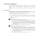
3. Notes on Designing ■ Notes on designing the printed circuit board for the user system If the header board is connected to a user system, the heights of parts mounted around the header board are restricted. When designing the printed circuit board of the user system, consider the heights of components within the range of the header board, as shown in Figure 1, so that the components mounted on the user system do not interfere with the header board. 88.0mm 23.0mm 42.0mm 150.0mm 52.
■ MCU footprint design notes Figure 2 shows the recommended dimensions of the NQPACK footprint mounted on the printed circuit board of the user system. The printed circuit board of the user system must be designed with due consideration given to this footprint as well as to the mass production MCU. For more information, contact the Tokyo Eletech Corporation. 0.65mm × 15 = 9.75mm 0.65mm 12.0mm 5.0mm φ2.2mm*2 3-φ1.0mm*1 0.65mm × 15 = 9.75mm 1.8mm 0.4mm 1.8mm No.1 pin 5.0mm 12.0mm 1.8mm 1.
4. Procedure for Connecting to the User System Before using the MB2198-304, mount the supplied NQPACK on the user system. Connect the header board directly to the adapter. Refer to the operation manual of the adapter for details on how to connect the adapter. ■ Connecting 1. To connect the header board to the user system, align pin 1 indicated by the index mark (▲) on the NQPACK mounted on the user system with the index mark (▲) on the header board and then insert it (See Figure 3) .
Screws for securing the header board Header board Washer YQPACK User system NQPACK Figure 4 Header board connection ■ Disconnection To disconnect the header board from the user system, remove all four screws, and then pull the header board straight out of the NQPACK.
5. Mounting Mass Production MCUs Use the supplied HQPACK to mount a mass production MCU on the user system. ■ Mounting 1. To mount a mass production MCU on the user system, align the index mark (▲) on the NQPACK mounted on the user system with the index mark (●) on the mass production MCU. 2.
6. Connector Pin Assignment The signals from the evaluation MCU mounted on the adapter board are connected to the YQPACK (the same assignments as mass production MCU) via adapter I/F connectors 1 and 2 on the header board. For details on the mass production MCU pins, refer to the data sheet or hardware manual of each MCU. ■ Pin assignment Tables 1 to 4 show the correspondence between the pin numbers for adapter I/F connectors 1 and 2, the evaluation MCU on the adapter board, and the mass production MCU.
Table 1 Adapter I/F Connector 1 (Row A) Connector Pin No. A1 A2 A3 A4 A5 A6 A7 A8 A9 A10 A11 A12 A13 A14 A15 A16 A17 A18 A19 A20 A21 A22 A23 A24 A25 A26 A27 A28 A29 A30 A31 A32 A33 A34 A35 A36 A37 A38 A39 A40 A41 A42 A43 A44 A45 A46 A47 A48 A49 A50 8 Mass Production Evaluation MCU MCU Pin No. Pin No.
Table 2 Adapter I/F Connector 1 (Row B) Connector Pin No. B1 B2 B3 B4 B5 B6 B7 B8 B9 B10 B11 B12 B13 B14 B15 B16 B17 B18 B19 B20 B21 B22 B23 B24 B25 B26 B27 B28 B29 B30 B31 B32 B33 B34 B35 B36 B37 B38 B39 B40 B41 B42 B43 B44 B45 B46 B47 B48 B49 B50 Mass Production Evaluation MCU MCU Pin No. Pin No.
Table 3 Adapter I/F Connector 2 (Row A) Connector Pin No. A1 A2 A3 A4 A5 A6 A7 A8 A9 A10 A11 A12 A13 A14 A15 A16 A17 A18 A19 A20 A21 A22 A23 A24 A25 A26 A27 A28 A29 A30 A31 A32 A33 A34 A35 A36 A37 A38 A39 A40 A41 A42 A43 A44 A45 A46 A47 A48 A49 A50 10 Mass Production Evaluation MCU MCU Pin No. Pin No. VCC VCC 11 B7 10 A8 C14 D13 15 C10 14 D9 20 A9 19 D10 GND GND E2 F2 D1 F4 C1 E4 D2 E3 GND GND H4 J4 F1 H2 E1 G2 F3 G3 GND GND K3 K4 H1 K2 G1 J2 H3 J3 GND GND D5 A3 D6 A4 C7 C6 A5 B5 Connector Pin No.
Table 4 Adapter I/F Connector 2 (Row B) Connector Pin No. B1 B2 B3 B4 B5 B6 B7 B8 B9 B10 B11 B12 B13 B14 B15 B16 B17 B18 B19 B20 B21 B22 B23 B24 B25 B26 B27 B28 B29 B30 B31 B32 B33 B34 B35 B36 B37 B38 B39 B40 B41 B42 B43 B44 B45 B46 B47 B48 B49 B50 Mass Production Evaluation MCU MCU Pin No. Pin No. R1 U4 V2 U3 U2 T3 R4 T4 GND GND W2 W3 V1 W4 U1 V4 T1 V3 GND GND AA1 AB1 Y2 AA4 Y1 Y4 W1 Y3 GND GND AC1 AC2 AB4 AC4 AB2 AB3 AA2 AA3 GND GND L36 K37 L35 M36 M35 L38 Connector Pin No.
SS01-71060-1E FUJITSU SEMICONDUCTOR • SUPPORT SYSTEM DSU-FR EMULATOR LQFP-64P HEADER TYPE 2 MB2198-304 OPERATION MANUAL February 2007 the first edition Published FUJITSU LIMITED Electronic Devices Edited Business Promotion Dept.