
Datasheet


Page 15/19
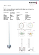
WLAN-Outdoor Bridgelink-Bundle
Order No.: 5510000271
The WLAN Outdoor Bridge Link Bundle “Out-of-the-Box” is designed for wireless bridging of radio links in
outdoor environments. The bundle contains all required components to setup a radio link by using the new
802.11n technology. This outdoor bundle contains two bintec WI1065n devices, which can be mounted
directly at the antenna pole. The WI1065n access points are water protected and allow operation
in temperature ranges between -25° C and +65° C.
The bundle contains also two PoE adapters, which enables
power supply over network cable. The dual polarization
antennas are transmitting the data over two streams, what
leads to higher performance of the system. The WLAN
Outdoor Bridgelink Bundle is intended to build radio links up
to 8 km distance.
The bundle contains following components:
Quantity Order No. Description
2 5010590013 bintec WI1065n
2 5500000551 ANT-N-20-5G Dual Polarization
4 600507 0,5m RTNC plug N plug LMR400
4 600499 Surge Arrester N plug N jack
2 5020591700 Pole mounting WI-65 Series
2 600258 PoE Injector
In case of free line of sight the results below can be expected by using the following configuration:
Configuration of the Access Point
Distance PHY rate
Operation
Band
Number of Spatial
Streams
Bandwidth
Transmit
Power
Allowed
EiRP
Minimum antenna
height
0,6 km 300 Mbit/s 5 GHz Outdoor 2 40 MHz 14 dBm 1000 mW 2 m
1,5 km 180 Mbit/s 5 GHz Outdoor 2 40 MHz 11 dBm 1000 mW 3 m
2,5 km 120 Mbit/s 5 GHz Outdoor 2 40 MHz 9 dBm 1000 mW 4 m
5 km 60 Mbit/s 5 GHz Outdoor 2 40 MHz 9 dBm 1000 mW 5,5 m
8,5 km 14,4 Mbit/s 5 GHz Outdoor 2 20 MHz 9 dBm 1000 mW 8 m
Hints to improve the operating distance:
- Use a antenna with higher gain
- Select 20 MHz bandwidth instead 40 MHz, or use only one stream.
-
Hints for installation:
- The link must be free from any obstacles (free line of sight). If necessary a different location must be
used or the antenna height must be increased.
- The antenna connectors of the Access Point ANT1 and ANT2 are connected to the antenna. It makes
no difference which antenna socket is used. The antenna connector ANT3 of the AP are not used for
these application.
- The antenna or rather the antenna pole must be connected with 16 mm
2
CU or more to the potential
equalisation. The Surge Arrestor protect the AP and must connected to the grounding of the building
with 1,5 mm
2
CU or more. The Surge Arrestor must be inserted in both antenna cables. In some
cases it is advisable to consult a specialist for lighting protection.