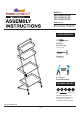
MODEL # YNJ-2052C25-DS YNJ-2052C31-DS YNJ-2052C35-DS Questions? GIVE US A CALL: 1-888-980-5122 MON-FRI 8:30AM-5:30PM (PST) TOOLS REQUIRED Phillips Screwdriver (Not Included) Hammer (Not Included) 2 - People Recommended ASSEMBLY RATING EASY DIFFICULT The Assembly Rating is a 5-point system showing the level of effort needed to assemble a specific product.
/ 23
/ 23
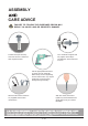
ASSEMBLY CARE ADVICE FAILURE TO FOLLOW THE GUIDELINES BELOW MAY RESULT IN INJURY AND/OR PROPERTY DAMAGE. Turn clockwise to tighten and only tighten when step is completed or when instructed to do so. Position each part correctly and insert screws or bolts into their respective holes. Use the appropriate hand tools or power tools for assembly. Select steps, such as tightening screws and/or bolts, may require hand tools to avoid causing damage during assembly.
/ 23
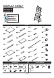
DISPLAY SHELF L YNJ-2052C25-DS YNJ-2052C31-DS YNJ-2052C35-DS I E A PARTS A 1PC G 1PC M 1PC T 1PC N 1PC H 3PCS U 2PCS B 1PC O 1PC V 1PC I 1PC C 1PC P 2PCS W 2PCS D 1PC J 1PC E 1PC Q 2PCS X 3PCS R 2PCS Y 2PCS K 1PC L 1PC F 1PC S 1PC ACCESSORIES HARDWARE 1 24PCS 2 24PCS 3 8PCS 4 8PCS 1.97" 6 2PCS 0.59" 7 6PCS 0.59" Z 1PC 8 17PCS 9 2PCS 5 4PCS A1 2PCS 10 2PCS 1.38" 6 / 23 A2 2SETS 1" 0.
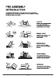
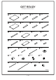
GET READY Please group boards as below.
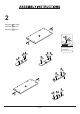
1 Hardware 1 x12PCS Hardware 3 x4PCS 3 Accessory A5 x1PC A 3 A5 3 OPTIONAL Apply a dab of glue into dowel holes of panels before inserting dowels (#3).
2 Hardware 1 x12PCS Hardware 3 x4PCS Accessory A5 x1PC 3 I 3 A5 3 OPTIONAL Apply a dab of glue into dowel holes of panels before inserting dowels (#3).
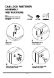
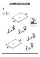
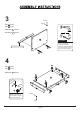
3 Front Top Part A x1PC Part D x1PC Hardware 4 x2PCS or Accessory A3 x1PC A3 D A RECOMMEND Recommend using a power tool to only tighten hardware (#4) faster. Accessory (#A3) could also work for hardware (#4) if a power tool is not present. hole facing to bottom 4 4 4 2 Part B x1PC Part C x1PC C Hardware 2 x6PCS 2 2 A 2 D 1 B 2 2 Please refer to page 5 for detailed instructions on how to fasten cam locks (#2) to cam bolts (#1).
5 Front Top Part E x1PC Part H x1PC Hardware 4 x2PCS or Accessory A3 x1PC A3 H E RECOMMEND hole facing to bottom Recommend using a power tool to only tighten hardware (#4) faster. Accessory (#A3) could also work for hardware (#4) if a power tool is not present. 4 4 6 2 Part F x1PC Part G x1PC G Hardware 2 x6PCS 2 2 E 2 2 H 1 F 2 Please refer to page 5 for detailed instructions on how to fasten cam locks (#2) to cam bolts (#1).
7 Hardware 7 x2PCS Accessory A1 x2PCS 7 A1 E Front Align the iron pieces (#A1) to panel (#E), then secure by using screws (#7). There will be no pre-drilled holes so the iron pieces (#A1) can be aligned at any distance from each other. Please refer page 23 to decide the position of iron pieces (#A1).
9 Part J x1PC Part K x1PC 1 2 Hardware 2 x6PCS 2 K Accessory A4 x4PCS 2 I 2 2 2 H Front J 2 Top Use the provided stickers (#A4) to cover exposed lock. 10 X4 Front Top Part L x1PC Part H x1PC Hardware 4 x2PCS Accessory A3 x1PC Accessory A4 x2PCS H or L A3 4 hole facing to bottom RECOMMEND 4 Use the provided stickers (#A4) to cover exposed screws. X2 13 / 23 Recommend using a power tool to only tighten hardware (#4) faster.
11 Part M x1PC Part N x1PC 1 2 Hardware 2 x6PCS 2 N Accessory A4 x4PCS 2 L 2 2 2 H M Front 2 Use the provided stickers (#A4) to cover exposed lock. Top 12 Part Part Part Part R V X Z Ensure all parts are attached with the same orientation as the diagram.
13 Part Part Part Part Q S T W x2PCS x1PC x1PC x2PCS Ensure all parts are attached with the same orientation as the diagram. Top Front X Q W X Q W Please ensure that the hole on part (#W) is facing inwards as shown in the diagram. T S The concave hole on part (#S) is facing inwards as shown in the diagram.
14 Part O x1PC Part P x2PCS Part Y x2PCS Front Top Y O Y Ensure all parts are attached with the same orientation as the diagram. The concave hole on part (#P) is aligned and facing inwards towards each other as shown in the arrows in the diagram. Y P Y P The hole on part (#Y) should be facing down as shown by the arrow in the diagram.
15 Front Hardware 6 x2PCS Top Ensure all parts are attached with the same orientation as the diagram.
17 Front Hardware 9 x2PCS Hardware 10 x2PCS Top 9 S 10 1st 2nd X2 18 Front Top N K G C 18 / 23
Hardware 8 x16PCS Accessory A3 x1PC Front Top Secure by using bolts (#8) in order as shown in the diagram.
Top Front Hardware 5 x4PCS Hardware 7 x4PCS Hardware 8 x1PC Accessory A3 x1PC Secure by using bolts (#8) and screws (#5,#7) in order as shown in the diagram.
Top The dimension is for reference, the dimension after the actual assembly shall prevail. 28.91" Align the product to the wall, then mark the wall with a pencil according to how you want to orient the product. 22 Please refer to page 23 on wall mounts. Use power drill (not included) to drill holes onto the marks on the wall.
23 Accessory A2 x2SETS A2 Top Front Secure unit onto the wall by using screws (#A2). Please ensure that the unit is properly aligned to the wall. Refer to page 23 on wall mounting guide. X2 24 ASSEMBLY COMPLETED Please ensure the furniture rests on an even and flat surface. If the produst wobbles or feels loose,double-check all bolts and/or screws are properly tightened and secured. Keep this handy! Please retain this instruction manual and any order-related information for future reference.
/ 23