C Yo u r L o c a l A g e n t/D e a le r 9-52, A shihara-cho, N ishinom iya, Japan Te l e p h o n e : Te l e f a x : 0 7 9 8 -6 5 -2 111 0798-65-4200 A ll rig h ts re s e rv e d . Printed in Japan PUB. No. OM E-34810 (YO SH ) M O DEL 1761 M ARK-3 FIRST EDITIO N D : : AUG. 1998 JUL.
SAFETY INSTRUCTIONS DANGER Stay away from transmitting antenna. The radar antenna emits microwave radiation which can be harmful to the human body, particularly the eyes. Never look directly into the antenna radiator from a distance of less than 1 m when the radar is in operation. Radio Frequency Radiation Hazard The radar antenna emits electromagnetic radio frequency (RF) energy which can be harmful, particularly to your eyes.
DANGER WARNING Use the proper fuse. Before turning on the radar make sure no one is near the scanner unit. Fuse rating is shown in the chapter 5. Use of a wrong fuse can result in equipment damage Prevent the potential risk of someone begin struck by the rotating antenna and exposure to RF radiation hazard. Do not operate the equipment with wet hands. Electrical shock can result. WARNING CAUTION Do not open the equipment. Do not use the equipment for other than its intended purpose.
FOREWORD Features Congratulations on your choice of the FURUNO MODEL 1761 MARK-3 Marine Radar. We are confident you will see why the FURUNO name has become synonymous with quality and reliability. Your radar has a large variety of functions, all contained in a remarkably small cabinet. The main features of the MODEL 1761 MARK-3 are: For over 50 years FURUNO Electric Company has enjoyed an enviable reputation for innovative and dependable marine electronics equipment.
TABLE OF CONTENTS 2.21 Adjusting Control Panel Brilliance ...... ..................................................... 2-8 2.22 Selecting Ranges ......................... 2-9 2.23 EBL/Cursor Bearing Reference ... 2-9 2.24 Guard Alarm ................................. 2-9 2.25 Watchman .................................. 2-10 2.26 Plotting ........................................ 2-11 2.27 Navigation Data Display .............. 2-11 FOREWORD .............................. iii MENU TREE ......................
MENU TREE MENU KEY 1. ECHO STRETCH (ON, OFF) 2. I. REJECT (OFF, ON) 3. PANEL DIMMER (0, 1, 2, 3, 4) 4. PLOT INTVL (CONT, 30S, 1M, 3M, 6M) 5. PLOT BRILL (LOW, @HIGH) 6. RANGE (NM) set with (RING) (1/4, 1/2, 3/4, 1, 1.5, 2, 3, 4, 6, 8, 12, 16, 24, 48) 7. WATCHMAN (OFF, 5M, 10M, 20M) 8. NAV DATA (ON, OFF) 9.
TABLE OF CONTENTS BY INDICATION, MARKER Elapsed time (P.2-11) Plotting interval (P.2-11) Plotting (P.2-11) Tuning indicator (P.2-11) MAG (or GYRO) BEARING (option) Echo stretch (P.2-8) Guard alarm (P.3-4) Heading marker (P.2-4) Range (P.2-2) Range ring interval (P.2-2) Shift (or Zoom) (P.2-6) 12 NM 3.0 NM SHIFT MAG 115.0 ¡ PLOT WATCHMAN 3M 18:25 ES *GUARD FTC IR FTC (P.2-4) Interference rejector (P.2-8) Watchman (P.2-10) EBL (P.2-6) Guard zone (P.2-9) Cursor (P.2-5, 6) EBL1 bearing (P.
SYSTEM CONFIGURATION Scanner Unit XN10A-RSB-0070-065 Navigation device IEC 61162* (In/Out) Display Unit Gyrocompass Gyro Converter AD-100 Intergrated Heading Sensor PG-1000 RDP-099 External Alarm Buzzer OP03-21 12 VDC: 10A 24/32 VDC: 5A Rectifier RU-3423 *Equivalent to NMEA 0183 Option 12/24/32 VDC vii 115/230 VAC
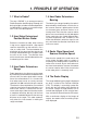
1. PRINCIPLE OF OPERATION 1.1 What is Radar? The term “RADAR” is an acronym meaning RAdio Detection And Ranging. Although the basic principles of radar were developed during World War II, echoes as an aid to navigation is not a new development. 1.2 How Ships Determined Position Before Radar Before the invention of radar, when running in fog near a rugged shoreline, ships would sound a short blast on their whistles, fire a shot, or strike a bell.
Heading marker Targets A D B A D B C C Own ship in center Own ship (radar) (A) Bird's eye view of situation (B) Radar picture of (A) Figure 1-1 How radar works 1-2 Range and bearing of a target, relative to own ship, are readable on the PPI.
2. OPERATION 2.1 Control Description Turns power on. Press together with [STBY/TX] key to turn power off. GAIN Alternates between stand-by and transmit. Lights (in green) to show the radar is in the "echonomy (stand-by)" mode. POWER PUSH/HM OFF OFF A/C SEA STBY TX ECONOMY Adjusts the brightness of the screen. Selects radar range. The "+" and "-" touchpads select a higher and lower range, respectively. Selets items during the menu display.
2.2 Turning the Radar On/Off 2.5 After confirming there are no crew near the scanner unit, press the [POWER] key to turn on the power. The range selected automatically determines the fixed range ring interval, the number of fixed range rings, pulselength, and pulse repetition rate, for optimal detection in short to long ranges. The range and ring interval appear at the top left corner of the display. The front panel will light up.
echoes and the background noise on the display. To adjust receiver sensitivity, transmit on long range, and adjust the [GAIN] control so background noise is just visible on the screen. Tips on adjusting GAIN • • • • In certain circumstances it may be useful to reduce the gain slightly to improve range resolution, clear up the picture, or reduce clutter caused by rain or snow.
2.9 Adjusting the A/C RAIN Control (reducing rain clutter) The vertical beamwidth of the antenna is designed to see surface targets even when the ship is rolling. However, by this design the unit will also detect rain clutter (rain, snow, hail, etc.) in the same manner as normal targets. Figure 2-3 shows the appearance of rain clutter on the display. Adjusting A/C RAIN When rain clutter masks echoes, adjust the [A/C RAIN] control.
2.13 Select the Cursor Data Display When connecting with NAV (IEC61162 format) and gyro converter (IEC61162 or AD10 format), this radar can show the cursor position by Latitude/longitude at bottom of screen. Each time pressing [HM OFF] key, the data will change from Range/Bearing to Latitude/ longitude and vice versa. When the cursor position is displayed by Latitude/Longitude, pressing the [HM OFF] key outputs L/L data of the cursor position (TLL) to the plotter.
2. Position the EBL so it bisects the target by operating the trackball. 3. Press the [EBL] key again to fix the EBL to the position. 4. Check the bearing readout to find the bearing of the target. To erase the EBL, press and hold down the [EBL] key for about three seconds. MAG (or GYRO) BEARING* 6.0 NM 2.0 MAG115.0° Target • Bearings of stationary or slower moving targets are more accurate than bearings of faster moving targets.
2. Press the [SHIFT/ZOOM] key. The indication “ZOOM” appears and brinks. 2.18 Menu Operation 3. To turn off the zoom, press the [SHIFT/ ZOOM] key again, or change the range. The menu, consisting of 9 items, mostly contains less-often used functions which once preset do not require regular adjustment. To open or close the menu, press the [MENU] key. You can select menus by using the trackball, then select item with the [RANGE] key. (Normal display) Place cursor where desired.
2.19 Echo Stretch Normally, the reflected echoes from long distance targets appear on the screen as weaker and smaller blips even through they are compensated by the radar’s internal circuitry. The Echo Stretch function magnifies these small blips. 1. Press the [MENU] key to open the menu. 2. Operate the trackball to select “1. ECHO STRETCH”. 3. Press the [RANGE] key to select “ON”. The indication “ES” appears at the upper right-hand side of the screen and the echoes are doubled lengthwise.
2.22 Selecting Ranges This radar has 14 ranges, some which you may not require. You can select or deselect ranges as follows. 1. Press the [MENU] key to open the menu. 2. Operate the trackball to select “6. RANGE”. 3. Press the [RANGE] key to place the underline under the range you want to select or deselect. 4. Press the [RING] key to select or deselect. 5. Repeat step 4 and 5. Maximum number of ranges is all ranges. Minimum number of ranges is two. 2.
Note 2: A target echo does not always mean a landmass, reef, ships or surface objects but can imply returns from sea surface or precipitation. As the level of these returns varies with environment, the operator should (properly) adjust the A/C SEA, A/C RAIN, FTC and GAIN to be sure target echoes within the guard zone are not overlooked by the alarm system. Note: The audible alarm does not sound for the target originally existing the zone.
1. Determine the guard zone (usually 360 degrees) with the guard alarm function. val (except for 15 seconds) appears to the right of the indication PLOT. 2. Press the [MENU] key to open the menu. If the range is changed during plotting, plotting begins anew with the newly selected range. To cancel plotting, press the [PLOT] key. 3. Operate the trackball to select “7. WATCHMAN” . 4. Press the [RANGE] key to select a transmission interval. 5. Press the [MENU] key to actuate the watchman mode.
If the output format is FURUNO CIF a jumper wire must be connected to “JUP1” on the SPU Board in the display unit. Note that for CIF format the bearing measurement method (Magnetic or True) does not appear for bearing to waypoint data. 12NM MAG 115.0° GUARD IR 3.0NM Waypoint Range to Waypoint Bearing to Waypoint M:Magnetic T:True (M or T appear in CIF format.) Own ships position (latitude and longitude) Ship's heading LL WP SPD 34°38.99S 6.0 NM 4.3 KT 135°19.22E 171.6° M HD 115.0° CRS 118.0° EBL 48.
3. FALSE ECHOES Occasionally false echoes appear on the screen at positions where there is no target. In some cases the effects can be reduced or eliminated. The operator should familiarize himself or herself with the appearance and effects of these false echoes, so as not to confuse them with echoes from legitimate contacts. 3.1 Multiple Echoes Multiple echoes occur when a short range, strong echo is received from a ship, bridge, or breakwater.
3.3 Indirect Echoes 3.4 Blind and Shadow Sectors Indirect echoes may be returned from either a passing ship or returned from a reflecting surface on your own ship, for example, a stack. In both cases, the echo will return from a legitimate contact to the scanner by the same indirect path. The echo will appear on the same bearing of the reflected surface, but at the same range as the direct echo. Figure 4-3 illustrates the effect of an indirect echo.
3.5 SART (Search and Rescue Transponder) A Search and Rescue Transponder (SART) may be triggered by any X-Band (3 cm) radar within a range of approximately 8 n.miles. Each radar pulse received causes it to transmit a response which is swept repetitively across the complete radar frequency band. When interrogated, it first sweeps rapidly (0.4 µs) through the band before beginning a relatively slow sweep (7.5 µs) through the band back to the starting frequency.
4. MAINTENANCE & TROUBLESHOOTING This chapter tells you how to keep your radar in good working order. Before reviewing this chapter please read the safety information which follows. DANGER Turn off the power before performing any maintenance or troubleshooting procedure. Hazardous voltages can shock, burn or cause death. Only qualified personnel totally famillier with electrical circuits should work inside the units. 4.1 Preventive Maintenance Regular maintenance is important for good performance.
4.3 Troubleshooting Table 4-2 contains simple troubleshooting procedures which you can follow to try to restore normal operation. If you cannot restore normal operation, do not attempt to check inside any unit of the radar system. Any repair work is best left to a qualified technician. Table 4-2 Troubleshooting table If... But... Then... you pressed the the control panel does • try adjusting the control panel back[POWER] key to turn not light lighting on the OTHERS menu.
4.4 Life Expectancy of Magnetron The following table shows the life expectancy of the magnetrons. Table 4-3 Life expectancy of magnetrons Magnetron Type Code No.
SPECIFICATIONS OF MARINE RADAR MODEL 1761 MARK-3 1. GENERAL 1.1. Indication System PPI Daylight display, raster scan, 8 tones in monochrome 1.2. Range, Pulselength (PL) & Pulse Repetition Rate (PRR) Range (nautical miles) PL PRR 0.125 0.25 SP 2100 Hz 1.3. 1.4. 1.5. 1.6. 1.7. 0.75 1.5 2 3 4 6 8 12 16 24 36 48 0.08 µs MP 1200 Hz LP 0.5 0.3 µs 0.8 µs 600 Hz Range Resolution Bearing Discrimination Minimum Range Bearing Accuracy Range Ring Accuracy 41 m 2.9º 39 m (0.25 NM range) Within 1º 0.
4. DISPLAY UNIT 4.1. Indication System 4.2. Picture Tube PPI Daylight display, raster scan, 8 tones in monochrome 7 inch rectangular monochrome CRT Effective display area more than 100 mm 4.3. Range, Range Interval, Number of Rings Range (NM) 0.25 0.5 0.75 1 1.5 2 3 4 6 8 12 16 24 48 Ring Interval (NM) 0.125 0.125 0.25 0.25 0.5 0.5 1 1 2 2 3 4 6 12 Number of Rings 2 4 3 4 3 4 3 4 3 4 4 4 4 4 4.1.
7. COATING COLOR 7.1. Display Unit 7.2. Antenna Unit Panel: N3.0, Chassis: 2.5GY5/1.5 N9.5 8. COMPASS SAFE DISTANCE 8.1. Display Unit 8.2. Antenna Unit Standard: 0.50 m Standard: 1.00 m SP - 3 Steering: 0.40 m Steering: 0.
Index A S A/C RAIN control .................................... 2-4 A/C SEA control .................................... 2-3 SART ....................................................... 3-2 Sensitivity ................................................ 2-2 Shadow Sectors ...................................... 3-2 Side-lobe Echoes .................................. 3-1 Stand-by .................................................. 2-2 ST BY/TX key ..........................................