BBWX1 Satellite Weather Receiver Installation and Maintenance Guide
Rev FUSA 15JUL2007 Table of Contents Safety Precautions ………………………………………… 3 Disclaimer …………………………………………………. 3 Contents of Package …………………………….…………4 Tools Required …………………………………….……….4 Installation General Precautions and Planning…………………5 Antenna Installation ……………………………...…6 Cable Installation ……………………………………9 BBWX1 Receiver Installation ………………………10 Typical System Diagrams ………………………………... 11 Activation ………………………………………………….. 12 Operation ………………………………………….……..….12 Troubleshooting - Diagnostics …………………………….
Safety Precautions: • Ensure power is turned off before attempting to install your weather system or carrying out routine maintenance. • This system is NOT intended for use on “positive” ground vessels. • Installation and operation of this equipment must be followed per these instructions. Failure to comply could result in personal injury, damage to your vessel and/ or poor product performance. • This equipment is intended as an aid only. Standard boating precautions still apply.
Contents of Package: • BBWX1 Receiver Module • SRA-40 Antenna Kit [includes 25 ft {7.6m} cable and mounting kit for various thicknesses of mounting substrate]. • Power Cable 10 ft [3m]. 3 pin connector, 20 AWG 2 wire and shield. • Ethernet Cable 10 ft [3m] • Screws [3] #10 x 1” long, Type A, S/ T, ST/ST for mounting Antenna. • Screws [3] #6 x 5/8” long, Type A, S/ T, ST/ST for mounting Receiver. • Operator’s Guide Tools Required: • Drill • Phillips screwdriver.
Installation: General Precautions and Planning: • Your vessels power system should be either: Negative grounded, with the negative battery terminal connected to the vessels ground, or floating with neither battery terminal connected to the vessels ground. It is important that an effective RF ground is connected to your weather system – if an RF system is installed. • The receiver should not be installed in an environment outside of the following temperatures: operating: 32 F to 131 F.
• The power cable supplied is 10 ft [3m], however it can be extended up to 60 ft [see power cable installation]. • The antenna cable supplied is 25 ft [7.6m], however alternative lengths can be ordered [35 ft, 50 ft, 90 ft and 135 ft. Be advised that the 135 ft cable comes with its own “inline amplifier”. Mounting the Antenna: • The antenna can be installed as a standard “pedestal” mounting or “surface” mounting [non metallic surface only].
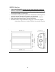
1. Remove the lower plastic body of the antenna [not the mounting base] and pass the short cable with its connector through. 2. Seal the hole around the shaft passing through with a suitable weather sealer [not supplied] before installing the lock washer and nut supplied. • For substrates between ¼” to 1” thick - only the 9/16” dia. hole is required. 1. As above, remove the lower plastic body of the antenna. 2.
Fig. 2 Fig.
Cable Installation: • The power cable, as supplied is 10 ft [3m] long, however it may be extended to a maximum of 60 ft [20m] using a suitable 16 AWG multi stranded cable. Red is positive, black is negative. • Should the shield wire of the power cable be required to be extended to reach the nearest ground point [RF ground preferred if installed on your vessel.] Use a 16 AWG multi strand wire. If your vessel does not have an RF system, connect the shield wire to the negative battery terminal.
BBWX1 Receiver: • Important REMINDER: Record both the Sirius Data and Audio Serial numbers as identified on the underside of your receiver before mounting. • Orientation of the unit to be such that the connector panel is pointing down and receiver be mounted on a vertical face. • A minimum of 6” [152mm] is required to be left below the connector panel to allow for adequate clearance for connections and cable bends. 1. Mark the location of the three fixing holes by using the unit as a template. 2.
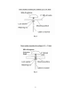
Typical system Diagrams: SRA-40 NavNet 6-Pin to 6-Pin Blue Network Cable and Hub Adapater Cable NavNet VX2 Display Ethernet Hub BBWX1 NavNet 6-Pin to 6-Pin Blue Network Cable and Hub Adapater Cable NavNet VX2 Display Dual Display / Processor SRA-40 To connect a single NavNet display to a BBWX1, use 000146-289 cable and an RJ-45 to RJ-45 Inline coupler, or use a standard NavNet Blue 6 pin to 6 pin network cable and a hub adapter cable (000-144-463) with a cross-over RJ-45 to RJ-45 Inline Coupler.
Initial Activation: 1. Power the receiver and confirm solid red LED for approx. 1 minute. This is followed by a solid amber to flashing amber to solid green to finally a flashing green LED [additional 0.5 minutes]. At this point the software is fully loaded and system is ready. 2. Turn on your display [refer to your individual user guide/ handbook for detailed information]. 3. Contact Sirius to “activate” your system.
Troubleshooting. BBWX1 Diagnostics: 1. The following identifies the “Key” to the LED blinking pattern as depicted on the connector panel of the receiver. KEY. FAULT Network disconnected: LED COLOR Amber PATTERN 1 sec. ON 1 sec. OFF 1 sec. ON 2 sec. OFF Antenna disconnected: Amber 1 sec. ON 2 sec. OFF Both disconnected: Amber System Ready: Green 1 sec. ON 1 sec. OFF 1 sec. ON 2 sec. OFF 1 sec. ON 2 sec.
GENERAL MAINTENANCE: • • Caution: Always turn your weather system OFF before carrying out routine maintenance. Your SDR is a sealed unit. DO NOT REMOVE the two end plates of the receiver. There are no user serviceable parts or adjustments inside. Any internal adjustments to be made must be carried out by an approved and qualified technician. Routine checks: • Examine all cables for signs of damage. • Check that all cables are supported. • Check that all connectors are fully inserted and supported.