Installation Manual MARINE RADAR MODEL1835/1935/1945 SAFETY INSTRUCTIONS .............................................................................................................i SYSTEM CONFIGURATION ........................................................................................................ii EQUIPMENT LISTS.....................................................................................................................iii 1. HOW TO INSTALL THE SYSTEM ...................................
SAFETY INSTRUCTIONS WARNING WARNING Radio Frequency Radiation Hazard Do not open the equipment unless totally familiar with electrical circuits and service manual. The radar antenna emits electromagnetic radio frequency (RF) energy which can be harmful, particularly to your eyes. Never look directly into the antenna aperture from a close distance while the radar is in operation or expose yourself to the transmitting antenna at a close distance.
SYSTEM CONFIGURATIONS MODEL 1835 Antenna unit RSB-0071-057 MODEL 1935 Antenna unit XN-10A RSB-0070/0073-064 MODEL 1945 Antenna unit XN-12A RSB-0070/0073-059 Display unit RDP-152 Heading sensor CANCEL HL OFF MENU Remote display ENTER Echo sounder GPS navigator AIS, etc. EBL VRM OFF CENTER TARGET ALARM TLL RANGE GAIN External buzzer CUSTOM A/C SEA TRAILS A/C RAIN Echo sounder GPS navigator AIS, etc.
EQUIPMENT LISTS Standard supply Name Type Display unit RDP-152 Antenna unit RSB-0071-057 XN10A-RSB-0070-064 XN10A-RSB-0073-064 Installation materials Code No.
Optional supply Name Code No. Qty PR-62 - 1 RU-3423 - External buzzer OP03-21 000-030-097 1 Cable assy.
1. HOW TO INSTALL THE SYSTEM 1.1 Display Unit Select a location for the display unit by following the information shown below. • The unit is waterproof, but FURUNO recommends that you install the display unit in a cabinet. • Keep the unit away from direct sunlight. • The temperature and humidity must meet the requirements shown in the equipment specifications. • Set the unit away from the exhaust pipes and vents. • The installation location must have enough cool air.
How to install the display unit in a console Follow the procedure shown below to install the display unit in a console. 1. Prepare a hole in the location whose dimensions are 274 (W) x 252 (H) mm. 2. Make four pilot holes. See the outline drawing at the back of this manual for additional information. 3. Set a flush mount sponge supplied as installation materials to the backside of the unit. 4. Set the unit to the hole. 5.
1.2 Antenna Unit for MODEL1835 How to select the location for the antenna unit When you select an installation location for the antenna unit, remember the following points. • Install the antenna unit on a solid location, for example radar arch or on a mast on a platform. (For sailboats, a mounting bracket is optionally available.) You must put the antenna unit where there is a good complete view. Make sure that no part of the superstructure is within the scanning beam.
How to install the antenna unit 1. Open the packing box of the antenna unit with great caution. 2. Loosen the four bolts at the base of the radome to remove the radome cover. Radome cover Antenna unit The location where you install the antenna unit must be parallel to the waterline. Make five holes in the installation location. See the outline drawing at the end of this manual for dimensions. A target echo returned from the bow direction must be shown on the zero degree position on the screen.
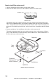
Antenna base plate Effective thread length Gasket Radome 25 mm 5 - 10 mm Flat washer Spring washer Apply silicone sealant. Platform M10 x 25 Hex bolt How to fasten the radome base to the platform Wiring and preparation 4. Make a hole of at least 20 millimeters in diameter through the deck or bulkhead to run the signal cable. (To prevent electrical interference, do not run the signal cable near other electrical equipment. Do not run the cable in parallel to power cables.) Set the cable through the hole.
to one of the screws of the cable clamping plate 9-pin connector: to J801 on MD-9208 4-pin connector: to J802 on MD-9208 13-pin connector: to J611 on IF-9214 Signal cable, the side of antenna unit J802 J801 MD-9208 Cable entry PTU-9335 J611 IF-9214 RF unit 1-6 www.busse-yachtshop.de | info@busse-yachtshop.
10. Attach the EMC core supplied as shown below. J801 J802 MD9208 J805 J804 J806 J803 Cable entrance Cable clamping plate EMC core E04SS251512 (Above cable clamping plate) Motor J1 J613 PTU-9335 J611 IF9214 How to attach EMC core 11.Attach the shield covers. Make sure the cable is not caught by the cover. 12.Attach the radome cover. Align the triangle mark on radome cover with that on radome base. Radome cover Radome base How to attach the radome cover 13.Fasten the radome bolts. 1-7 www.
How to install the optional mounting bracket The optional mounting bracket lets you fasten the antenna unit to a mast on a sailboat. Mounting bracket kit Type: OP03-92 Code No.
1.3 Antenna Unit for MODEL1935/1945 How to select the location for the antenna unit • The antenna unit is installed either on top of the wheelhouse or a platform on the radar mast. Install the antenna unit where there is a good complete view. Any obstruction causes blind sectors. For example, a mast with a diameter smaller than the horizontal beamwidth of the radiator causes only a small blind sector. A horizontal spreader or crosstrees in the same horizontal plane creates a large obstruction.
Installation procedure Refer to the outline drawing at the back of this manual for the dimensions. Make five holes in the platform. Four holes to fasten the antenna unit and one hole for the signal cable. How to fasten the radiator to the radiator bracket See the packing list at the back of this manual for the installation materials. 1. Remove the radiator cap from the radiator bracket. 2. Apply the silicone sealant to the surface of the antenna radiator and the radiator bracket.
How to install the antenna unit You can install the antenna unit by one of the two methods shown below. • Use the outside holes • Use the inside holes How to use outside holes of the antenna housing Use the hex head bolts (supplied) to install the antenna unit as shown in the illustration below. 1. Put the rubber mat (supplied) on the platform. Ground terminal Rubber mat Bow mark Location of rubber mat 2. Put the antenna unit on the rubber mat.
3. Set four hex head bolts (M12x60, supplied) and seal washers (supplied) from the top of the antenna housing, as shown below. Hex bolt Seal washer Flat washer Spring washer Nut How to set the antenna unit chassis 4. Set the flat washers (M12, supplied), spring washers (supplied) and nuts (supplied) to the hex head bolts. Tighten by turning the nuts. Do not tighten by turning the hex head bolts, to prevent damage to the seal washers.
8. Apply the silicone sealant to the ground terminal and ground point as shown below. Hex bolt Flat washer Ground wire Silicone sealant Flat washer Spring washer Hex nut OR GROUND POINT Hex nut Spring washer Flat washer Hex nut Ground wire Weld here.
Upper chassis Hex head bolt M8 x 25 2 pcs. RFunit Hex head bolt M10 x 20, 4 pcs. Pan head screw M3 x 8, 2 pcs. Spring Washer M10, 4 pcs. Pan head screw M3 x 8, 2 pcs. Board cover Square bushing Lower chassis Antenna unit chassis, upper chassis separated 7. Set the corrosion-proof rubber mat (supplied) to the support platform. 8. Cut the rubber bushings in the fixing holes and put four bolts from the inside of the lower chassis.
How to connect the signal cable The signal cable runs from the display unit to the antenna unit. To reduce the electrical interference, do not run the signal cable near other electrical equipment. And do not run the cable in parallel to power cables. Put the cable through the hole and apply the sealing compound around the hole for waterproofing. 1. Loosen four bolts, open the antenna cover, and set the stay. Stay Cable gland assy. Bolt Antenna unit chassis, cover opened 2.
5. Put the signal cable so that no more than 4 cm of the sheath is visible, as shown in the figure below. Tighten the fixing bolts. Taping Shield wire Sheath Bolt Within 4 cm Plate Gasket Flat washer CABLE GLAND How to fasten signal cable in cable gland 6. Loosen four screws in the figure shown below and open the cover. Four screws Antenna unit chassis, cover opened 7. Put the signal cable through the cable protector. Cable protector Antenna unit chassis, cover opened 1-16 www.busse-yachtshop.
8. Connect the signal cable to the RTB Board (03P9249). See the interconnection diagram and the figure shown below. 9. Attach three EMI cores to the signal cable as shown below. RTB Board J821 VH9P J822 VH2P J824 NH13P Lead in cable here. J823 VH4P EMI core RFC-13 Clamp Run cable along here. Antenna unit chassis, cover opened 10.Fasten the signal cable with the cable clamp. 11.Undo the stay and close the cover. Securely fasten the scanner bolts.
This page is intentionally blank. 1-18 www.busse-yachtshop.de | info@busse-yachtshop.
2. CABLE CONNECTION 2.1 Standard Connection Connect all cables at the rear of the display unit. DJ-1 Antenna cable MJ-B24LPF0002-xxx+R or MJ-B24LPF0005-yyy+R To antenna unit USB HDG (xxx: 100, 150, 200 or 300) (yyy: 050, 100, 150, 200 or 300) NMEA1 NMEA2 1+ 2- OPTION 3 GND 12-24 VDC/ 8.0-3.8A Ground terminal Connect ground wire between here and ship's ground. Power cable MJ-A3SPF0017-050ZC CAUTION Ground the equipment to prevent interference.
2.2 Data Signal Port Connect external equipment(s) to the ports on the rear panel as shown below. NMEA1 (7P), NMEA2 (7P) (NMEA in / out) HDG (6P) OPTION (10P) GPS sensor, AIS GPS navigator, echo sounder, etc. Heading sensor (Example AD-100, SC-50, SC110) External buzzer Remote display Necessary cable MJ-A7SPF0007-050C Necessary cable MJ-A6SPF0007-100C Necessary cable See section 4.2. DJ-1 USB HDG HDG port NMEA1 NMEA1 port NMEA2 NMEA2 port 1+ 2- OPTION OPTION port 3 GND 12-24 VDC/ 8.0-3.
3. HOW TO SET THE EQUIPMENT 3.1 How to Set the Language At the first power application after installation, select a language as follows. 1. Press /BRILL key to turn on the power. "Now Initializing" appears and after a while the window below appears. 2. Use the cursor pad to select a language required and press the ENTER key. The window shown below appears. Language English OK? Yes No Language selected 3. Select Yes and press the ENTER key. 3-1 www.busse-yachtshop.de | info@busse-yachtshop.
3.2 How to Set the Purpose Set the purpose of the radar. 1. Press the MENU key. The main menu appears on the screen. 2. Press T or S on the cursor pad to select Factory. The factory menu title bar appears in gray on the right of the screen. 3. While you press the CANCEL/HL OFF key, press the MENU key five times to activate the Factory menu.
3.3 How to Enter the Initial Settings After you set the purpose of the radar, enter the initial settings as follows. 1. On the main menu, press T or S to select Installation. Installation Menu Target ARPA AIS GPS System Initial Tests Sector Blank ** Units Installation Factory Input Source ARPA QV Select Demo Mode Antenna Rotation Antenna Height Near STC Level A/C Auto Adjust Heading Adjust Timing Adjust : Master : Off : Off : Rotate : 15m :2 :0 : 0. 0 ° : 0.
Antenna Height: Set the height of the antenna above the water surface. The options are 5, 10, 15, 20, 30, 40 and 50 m. The default setting is 15 m. Near STC Level: Set the STC curve at near distance. The options are 1,2, 3 and 4. “4” has the strongest effect. A/C Auto Adjust: Adjust the performance of the automatic A/C. Memory Clear: Restore the default settings. Purpose, Type and Input Source are not changed. When turning on the power after the memory clear, the language selection window appears.
How to automatically set the equipment The equipment automatically adjusts the tuning, timing and video. Note: Before you do this procedure, tramsmit the radar more than 10 minutes on a long range and check that Sector Blank is OFF. 1. Transmit on the maximum range. 2. Select Auto Install Setup from the installation menu and press the ENTER key. 3. Press S on the cursor pad to select Yes, then press the ENTER key.
Manual MBS Adjustment Reduce the main bang (black hole), which appears at the display center on short ranges, as follows. 1. Transmit the radar on the shortest range. 2. Open the Installation menu and select MBS Adjust. 3. Press the ENTER key to show the setting window. 4. Press the cursor pad to reduce the main bang (between 0 and 25). 5. Press the ENTER key to finish. Video Initial Adjustment After you complete the automatic installation setting, tune the video signal if necessary. 1.
4. OPTIONAL EQUIPMENT 4.1 ARP Kit ARP-11 The ARP kit provides automatic radar plotter functions to this radar. Necessary parts Name: ARP kit Type: ARP-11 Code no.: 008-523-050 For details, see the packing list attached to the kit. 1. Unscrew 12 screws and five connector nuts at the rear of the display unit. Remove 12 screws. Remove five connector nuts. Do not remove this connector nut. Rear panel of Display unit 4-1 www.busse-yachtshop.de | info@busse-yachtshop.
2. Lift the cover slowly and open it as shown below. Cover Take care not to damage this cable assembly. Open this direction. 03P9474 J214 3. Mate P107 on the ARP board to J214 on the 03P9474 board and fasten the ARP board with four screws. ARP board Comfirm that rubber gasket is set securely in the groove around the panel. 4-2 www.busse-yachtshop.de | info@busse-yachtshop.
4. Reassemble the display unit. DJ-1 Torque 2.94±0.29 Nm USB HDG NMEA1 NMEA2 1+ 2- OPTION Torque 0.78±0.08 Nm 3 GND 12-24 VDC/ 8.0-3.8A Torque 0.78±0.08 Nm (12 pcs) 4-3 www.busse-yachtshop.de | info@busse-yachtshop.
4.2 Connection of Buzzer and/or Remote Display You need the cables shown below to connect the optional external buzzer and remote display. • Two-way cable MJ-A10SPFW0001+R • MJ-A7SPF0007-050C • MJ-B24LPF0010-xxx+R (xxx: 100, 200 or 300) Display unit RDP-152 MJ-A10SPFW0001+R * (0.
NAME www.busse-yachtshop.de | info@busse-yachtshop.de DOCUMENT 000-157-995-10 MJ-A3SPF0017-050ZC 000-170-325-1* C32-00802 000-807-986-1* J39-60060-* 001-058-460-00 CP03-32901 ** CP03-32900 001-058-470-00 FP03-11601 000-086-965-00 SP03-12200 000-014-615-00 RDP-152-* 1 1 1 1 1 1 1 Q'TY (略図の寸法は、参考値です。 DIMENSIONS IN DRAWING FOR REFERENCE ONLY.
PACKING LIST 19AL-X-9852 -4 1/1 RSB-0071-057/J N A M E ユニット O U T L I N E DESCRIPTION/CODE № Q'TY UNIT 空中線部 1 RSB-0071-057 ANTENNA UNIT 000-086-830-00 空中線部工材 ANTENNA UNIT INSTALLATION MATERIALS ** CP03-16901 EMCコア 1 E04SS251512 EMC CORE 000-144-673-00 六角スリワリ ボルト HEX.
A-3 CODE NO. 008-503-360-00 TYPE CP03-18401 03FR-X-9401 -13 1/2 工事材料表 INSTALLATION MATERIALS 番 号 NO. 名 称 NAME 数量 Q'TY 型名/規格 DESCRIPTIONS 略 図 OUTLINE 用途/備考 REMARKS シールワッシャ 1 03-001-3002-0 ROHS SEAL WASHER 4 CODE NO. 300-130-020-10 防蝕ゴム 2 03-142-3001-0 ROHS CORROSION-PROOF RUBBER MAT 1 CODE NO. 100-275-580-10 キャップ 3 040-4010 CAP 4 CODE NO. 000-164-929-10 バネ座金 4 M12 SUS304 SPRING WASHER 4 CODE NO. 000-167-397-10 ミガキマル平座金 5 M12 SUS304 FLAT WASHER 4 CODE NO.
A-4 CODE NO. 008-503-360-00 TYPE CP03-18401 03FR-X-9401 -13 2/2 工事材料表 INSTALLATION MATERIALS 番 号 NO. 名 称 NAME 数量 Q'TY 型名/規格 DESCRIPTIONS 略 図 OUTLINE 用途/備考 REMARKS 六角ボルト 11 M6X25 SUS304 HEX.BOLT 1 CODE NO. 000-162-871-10 EMIコア 12 RFC-13 EMI CORE 3 CODE NO. 000-141-084-11 アース線 13 RW-4747-1 GROUND WIRE 1 CODE NO. 000-566-000-01 型式/コード番号が2段の場合、下段より上段に代わる過渡期品であり、どちらかが入っています。 TWO TYPES AND CODES MAY BE LISTED FOR AN ITEM. QUALITY IS THE SAME.
A-5 03HD-X-9402 -0 CODE NO. 1/1 TYPE 工事材料表 MODEL1835 INSTALLATION MATERIALS 番 号 NO. 名 称 NAME 数量 Q'TY 型名/規格 DESCRIPTIONS 略 図 OUTLINE 選択 TO BE SELECT ケーブル組品MJ 1 MJ-B24LPF0002-100+R CABLE ASSY. 用途/備考 REMARKS 1 CODE NO. 000-138-972-12 選択 TO BE SELECT ケーブル組品MJ 2 MJ-B24LPF0002-150+R CABLE ASSY. 1 CODE NO. 000-138-970-12 選択 TO BE SELECT ケーブル組品MJ 3 MJ-B24LPF0002-200+R CABLE ASSY. 1 CODE NO. 000-138-974-12 選択 TO BE SELECT ケーブル組品MJ 4 MJ-B24LPF0002-300+R CABLE ASSY. 1 CODE NO.
A-6 03HD-X-9403 -0 CODE NO. 1/1 TYPE 工事材料表 MODEL1935/1945 INSTALLATION MATERIALS 番 号 NO. 名 称 NAME 数量 Q'TY 型名/規格 DESCRIPTIONS 略 図 OUTLINE 選択 TO BE SELECT ケーブル組品MJ 1 MJ-B24LPF0005-050+R CABLE ASSY. 用途/備考 REMARKS 1 CODE NO. 000-143-736-12 選択 TO BE SELECT ケーブル組品MJ 2 MJ-B24LPF0005-100+R CABLE ASSY. 1 CODE NO. 000-140-434-12 選択 TO BE SELECT ケーブル組品MJ 3 MJ-B24LPF0005-150+R CABLE ASSY. 1 CODE NO. 000-140-435-12 選択 TO BE SELECT ケーブル組品MJ 4 MJ-B24LPF0005-200+R CABLE ASSY. 1 CODE NO.
D-1 Y. Hatai www.busse-yachtshop.de | info@busse-yachtshop.
Y. Hatai D-2 www.busse-yachtshop.de | info@busse-yachtshop.
5/Feb/09 R.Esumi D-3 www.busse-yachtshop.de | info@busse-yachtshop.
5/Feb/09 R.Esumi D-4 www.busse-yachtshop.de | info@busse-yachtshop.
www.busse-yachtshop.de | info@busse-yachtshop.de C B A DATA-H DATA-C CLK-H CLK-C SHIELD TD-A TD-B SHIELD *2 MJ-A6SPF0007,10m MJ-A6SPF0003,5/10m 同上 DITTO または OR スマートセンサー SMART SENSOR DST-800 GPS受信機 *2 GPS RECEIVER GP-320B/330B MJ-A10SPF 10m MJ-A7SPF MJ-A7SPF MJ-A6SPF シロ WHT クロ BLK キ YEL ミドリ GRN NOTE *1: SHIPYARD SUPPLY. *2: OPTION. *3: SHIELD SHOULD BE GROUNDED EFFECTIVELY AT BOTH END. *4: DEFAULT:10A. REPLACE FUSE TO 5A FOR 24V USE.
www.busse-yachtshop.de | info@busse-yachtshop.de C B A DATA-H DATA-C CLK-H CLK-C SHIELD TD-A TD-B SHIELD *2 MJ-A6SPF0007,10m MJ-A6SPF0003,5/10m 同上 DITTO または OR スマートセンサー SMART SENSOR DST-800 GPS受信機 *2 GPS RECEIVER GP-320B/330B MJ-A10SPF 10m シロ クロ キ ミドリ MJ-A7SPF MJ-A7SPF MJ-A6SPF WHT BLK YEL GRN NOTE *1: SHIPYARD SUPPLY. *2: OPTION. *3: SHIELD SHOULD BE GROUNDED EFFECTIVELY AT BOTH END. *4: DEFAULT: 10A. REPLACE FUSE TO 5A FOR 24V USE.
The paper used in this manual is elemental chlorine free. ・FURUNO Authorized Distributor/Dealer 9-52 Ashihara-cho, Nishinomiya, 662-8580, JAPAN Telephone : +81-(0)798-65-2111 Fax : +81-(0)798-65-4200 All rights reserved. Printed in Japan A : FEB . 2009 Pub. No. IME-35790-A (TATA ) MODEL1835/1935/1945 *00017025110* *00017025110* * 0 0 0 1 7 0 2 5 1 1 0 * www.busse-yachtshop.de | info@busse-yachtshop.