
Installation Instructions


17-364-01 rev. 05 03/16/11
Thru-Hull, without Valve
Tilted Element
™
Transducer
Tilt Angles: 0
°
, 12
°
, 20
°
Models: B60, B75H, B75L, B75M, B619
P19, SS60, SS565, SS619
U.S. Patent No. 7,369,458. UK Patent No. 2 414 077. U.S. Patent Pending
Applications
• Plastic housing recommended for fiberglass or metal hulls only.
Never install a plastic housing in a wood hull since swelling of
the wood can fracture the plastic.
• Bronze housing recommended for fiberglass or wood hulls.
Never install a bronze housing in a metal hull, because
electrolytic corrosion will occur.
• Stainless steel housing compatible with all hull materials.
Recommended for metal hulls to prevent electrolytic corrosion
provided the stainless steel housing is isolated from the metal hull.
Match Tilt Angle of Transducer to Deadrise
Be sure the tilt angle of your transducer model matches the
deadrise angle of your boat at the mounting location. The tilt angle
is printed on the top of the transducer (see Figure 1). To measure
the deadrise angle of your hull at the selected mounting location,
use an angle finder or a digital level (see Figure 2).
• 0° models—For hull deadrise angles from 0° to 7°
• 12° models—For hull deadrise angles from 8° to 15°
B75L-12°—For hull deadrise angles from 0° to 24°
B75H-12°—For hull deadrise angles from 6° to 15°
B75M-12°—For hull deadrise angles from 6° to 15°
• 20° models—For hull deadrise angles from 16° to 24°
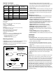
Figure 2. Deadrise angle of the hull
transom view
deadrise angle
slope of hull
parallel to waterline
Figure 1. Top of transducer
12
O
TILT
KEEL
20
O
TILT
KEEL
P19
12° model 20° model
Copyright © 2005 Airmar Technology Corp.
Copyright © 2005 Airmar Technology Corp.
INSTALLATION INSTRUCTIONSOWNER’S GUIDE &
Record the information found on the cable tag for future reference.
Part No._________________Date___________Frequency________kHz
AIRMAR®
AIRMAR®
Follow the precautions below for optimal product
performance and to reduce the risk of property damage,
personal injury, and/or death.
WARNING: Always wear safety goggles and a dust
mask when installing.
WARNING: Immediately check for leaks when the
boat is placed in the water. Do not leave the boat
unchecked for more than three hours. Even a small
leak may allow considerable water to accumulate.
WARNING: B619 and SS619—Do not use the spacer
if there is insufficient space to tighten the nut, or it is
within 11mm (1/2") of the top of the housing.
WARNING: Stainless steel housing in a metal hull—
Be sure the washer contacts the hull. Do not tighten
the hull nut with the washer against the isolation
bushing, as the housing will not be firmly installed. If
necessary, sand the isolation bushing until the washer
rests against the hull.
CAUTION: The arrow on the top of the transducer
must point toward the keel or centerline of the boat.
This will align the angle of the element inside the
transducer with the deadrise angle of your hull.
CAUTION: Never pull, carry, or hold the transducer by
its cable; this may sever internal connections.
CAUTION: Never install a metal transducer on a
vessel with a positive ground system.
CAUTION: Plastic housing—Never use a fairing with
a plastic housing; the protruding sensor would be
vulnerable to damage from impact.
CAUTION: Metal housing—Never install a metal
housing on a vessel with a positive ground system.
CAUTION: Stainless steel housing in a metal hull—
The stainless steel housing must be isolated from a
metal hull to prevent electrolytic corrosion. Use the
isolation bushing supplied.
CAUTION: Never use solvents. Cleaners, fuel,
sealants, paint, and other products may contain strong
solvents, such as acetone, which attack many
plastics, greatly reducing their strength.
IMPORTANT: Read the instructions completely
before proceeding with the installation. These
instructions supersede any other instructions in your
instrument manual if they differ.