3. SETTINGS AND STATUS 3.2 Overview of the AIS Setting Tool 1 4 2 5 6 3 7 8 9 No. 1 [Tools] Name 2 [Help] • • • • Description [Disconnect]: Disconnects from the FA-70. [Screenshot…]: Takes a screenshot. [Usage Considerations]: Shows the precautions for use. [About]: Shows the program version number. 1 xx 3 4 Port selection [Connect]/[Disconnect] 5 [Refresh All] 6 [Apply All] 7 8 Menu tab Setting/Display area 9 [Apply] 3-2 xx denotes minor modifications.
3. SETTINGS AND STATUS 3.3 IO setup (input/output port) You can change the input/output settings from the [IO Setup] menu. [CAN Unique Number], [CAN Address]: Display only.
. SETTINGS AND STATUS 3.4 Own Vessel Data Screen The [Own Vessel Data] screen shows the information of AIS channel, sensor status, and GNSS status. JAN Internal DGNSS in Use (Message 17) Internal SOG/COG in Use Heading Valid Channel Management Parameters Changed [Own Vessel Data] screen for PC Menu item [View Channel] [CH A] [CH B] [Power] [Region List] (for the PC) [Sensor Status] [GNSS Status] (for the PC) 3-4 Description Shows the channel number and TX/RX mode for channel A.
3. SETTINGS AND STATUS 3.5 Alert Status The [Alert Status] screen shows the alerts currently occured. 01/JAN/2020 18:30 01/JAN/2020 18:31 01/JAN/2020 18:32 01/JAN/2020 18:35 01/JAN/2020 18:37 [Alert Status] screen for PC • [Time [UTC]]: Shows the time and date when the alert occured. • [ID]: Shows the alert number. • [Alert]: Shows the alert message*. *: For the external display, select the alert ID to display the alert message on the bottom of the screen.
3. SETTINGS AND STATUS 3.6 IO Monitor The data input from each port can be monitored. Note: This menu appears only on the PC. Character count Display area of receiving data • [Port]: Select the port that displays the received data. • [Start]: Click to start the receiving data display. The displayed characters are up to 10000 characters. The [Start] button changes to the [Stop] button. • [Stop]: Click to stop the receiving data display. The [Stop] button changes to the [Start] button.
4. MAINTENANCE WARNING NOTICE ELECTRICAL SHOCK HAZARD Do not open the equipment. Only qualified personnel can work inside the equipment. 4.1 Do not apply paint, anti-corrosive sealant or contact spray to coating or plastic parts of the equipment. Those items contain organic solvents that can damage coating and plastic parts, especially plastic connectors. Maintenance Regular maintenance helps good performance. Check the items listed below monthly to keep your equipment in good working order.
4. MAINTENANCE 4.3 Troubleshooting The troubleshooting table below provides typical operating problems and the means to restore normal operation. If you cannot restore normal operation, do not open the cover of the FA-70; there are no user serviceable parts inside the transponder. Symptom Remedy Cannot turn on the power. • Check that the cable between the transponder and power for damage. • Check the power supply. • Check the fuse. Cannot transmit/receive.
4. MAINTENANCE Menu item [Test Start] (for the PC) [Transponder Test] [GNSS Test] [Clear GNSS] (for the PC) Description Click to start the test. The program version number appears on the first line. The RAM, ROM, two RX channels (A and B) and TX are checked for proper operation, and the results are displayed as "OK" or "NG" (No Good). For any NG, contact your dealer for advice. When the VHF spliter board is connected, "Used" appears, not connected, "Unused" appears on the last line.
4. MAINTENANCE This page is intentionally left blank.
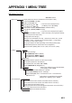
APPENDIX 1 MENU TREE AIS Setting Tool (PC) Bold italic: Default Initial Setup Status (Shows the status for transmission and reception of AIS.) TX Mode (SOTDMA, CSTDMA) SART Test RX (OFF, ON) *1 : This menu item is displayed when DSC Monitoring (OFF, ON) [TX Mode ] is set to [SOTDMA]. Long-Range TX*1 (OFF, ON) Silent Mode Controller (Hardware Switch, Software Switch) Silent Mode*2 (Normal (TX/RX), RX Only) *2 : This menu item is displayed when [Silent Ship Static MMSI (Enter the MMSI number.
APPENDIX 1 MENU TREE 1 Alert Status (Shows the alerts currently occured.) Alert Log (Shows the alerts occured in the past.) Tests IO Monitor Test Start (Starts the test.) Transponder Test (Shows the self test result for the FA-70.) GNSS Test (Shows the self test result for the internal GNSS core.) Clear GNSS (Clears the GNSS test result.
APPENDIX 1 MENU TREE 1 IO Setup Port Priority (Heading) 1st (NMEA2000, NMEA1, NMEA2) 2nd (NMEA2000, NMEA1, NMEA2) 3rd (NMEA2000, NMEA1, NMEA2) NMEA2000 CAN Unique Number (Shows the CAN unique number.) CAN Address (Shows the CAN address.
APPENDIX 2 ALERT LISTS The table below shows the alert ID, text, meaning and remedy for each alert. ID 001 Text TX Malfunction 002 Antenna VSWR Exceeds Limit 003 004 007 026 029 030 AP-4 Meaning Transmission stopped due to a failure. (The ERROR LED lights in red.) High VSWR for the AIS antenna detected. (Continued operation possible.) RX Channel 1 RX1 hardware trouble. Malfunction Transmission stopped on corresponding TX channel. (The ERROR LED lights in red.) RX Channel 2 RX2 hardware trouble.
APPENDIX 3 NMEA2000/0183 INPUT/ OUTPUT DATA CAN bus (NMEA2000) input/output Input PGN PGN 059392 059904 060160 060416 060928 065240 126208 127250 Description ISO Acknowledgment ISO Request ISO Transport Protocol, Data Transfer ISO Transport Protocol, Connection Management - BAM Group Function ISO Address Claim ISO Commanded Address NMEA - Request Group Function NMEA - Command Group Function Vessel Heading Output PGN PGN 059392 059904 060928 126208 126464 Output cycle*1 (ms) 126992 126993 126996 Descrip
APPENDIX 3 NMEA2000/0183 INPUT/OUTPUT DATA *1: *2 Output cycle*1 (ms) PGN 129801 129802 129803 129804 Description AIS Addressed Safety Related Message AIS Safety Related Broadcast Message AIS Interrogation AIS Assignment Mode Command *3 129805 129806 129807 129809 129810 129811 129812 AIS Data Link Management Message AIS Channel Management AIS Group Assignment AIS Class B “CS” Static Data Report, Part A AIS Class B "CS" Static Data Report, Part B AIS Single Slot Binary Message AIS Multi Slot Binary M
APPENDIX 4 RADIO REGULATORY INFORMATION USA-Federal Communications Commission (FCC) This device complies with part 15 of the FCC Rules. Operation is subject to the following two conditions: (1) This device may not cause harmful interference, and (2) This device must accept any interference received, including interference that may cause undesired operation. Any changes or modifications not expressly approved by the party responsible for compliance could void the user's authority to operate the equipment.
FURUNO FA-70 SPECIFICATIONS OF CLASS B AIS TRANSPONDER FA-70 1 1.1 1.2 GENERAL Type RX capacity 2 2.1 2.2 2.3 2.4 2.5 2.6 TRANSMITTER Frequency range Output power Modulation Channel interval Frequency deviation Spurious emission 2.7 Transmission interval SOTDMA Class B AIS Transponder 2250 report/minute, 1 channel 4500 report/minute, 2 channel 1.3 RX system SOTDMA or CSTDMA (user select), dual wave simultaneous reception 1.
FURUNO FA-70 4.3 4.4 4.5 4.6 4.7 4.8 Error at high input level -7 dBm (PER10% or less) Co-channel rejection -10 dB or more Adjacent channel selectivity 70 dB or more Spurious response 70 dB or more Inter-modulation 65 dB or more Sensitivity suppression 84 dB 5 5.1 VHF SPLITTER Rx function Frequency range Insertion loss Tx function Frequency range Insertion loss Input power Power detection 155 MHz to 164 MHz 1 dB or less 25 W max. 0.1 W or more 6 6.1 6.2 6.3 6.4 6.5 6.6 6.7 6.
FURUNO 8 FA-70 POWER SUPPLY 12-24 VDC (9.6-31.2 VDC): 1.8-0.9 A (TX), 0.3-0.2 A (RX) 9 9.1 9.2 9.3 9.4 ENVIRONMENTAL CONDITIONS Ambient temperature Antenna unit -25°C to +70°C Transponder -15°C to +55°C Relative humidity 93% or less at +40°C Degree of protection Antenna unit IP56 Transponder IP55 Vibration IEC 60945 Ed.4 10 UNIT COLOR 10.1 Antenna unit 10.2 Transponder N9.5 N1.
D-1 18/Oct/2019 H.
D-2 7/Apr/2017 H.
D-3 Mar.27'07 R.
C B A NOTE *1: SHIPYARD SUPPLY. *2: OPTION. 注記 *1)造船所手配。 *2)オプション。 外部スイッチ EXTERNAL SWITCH 航法機器または センサー NAV EQUIPMENT OR SENSOR (+) (-) 12-24VDC 航法機器または センサー NAV EQUIPMENT OR M-P-5 2m 5A アカ RED クロ BLK シロ WHT チャ BRN キ YEL ミドリ GRN ドレイン DRAIN ムラサキ PPL ハイ GRY *2 MJ-A6SPF0003,15m MAX.
INDEX A AC-DC power supply.........................................................................................................................1-8 AIS Setting Tool Installation .......................................................................................................................................2-2 AIS setting tool Overview .........................................................................................................................................3-2 Start, Quit .............
Declaration of Conformity [FA-70] Bulgarian (BG) С настоящото Furuno Electric Co., Ltd. декларира, че гореспоменат тип радиосъоръжение е в съответствие с Директива 2014/53/ЕС. Цялостният текст на ЕС декларацията за съответствие може да се намери на следния интернет адрес: Spanish (ES) Por la presente, Furuno Electric Co., Ltd. declara que el tipo de equipo radioeléctrico arriba mencionado es conforme con la Directiva 2014/53/UE.
Lithuanian Aš, Furuno Electric Co., Ltd., patvirtinu, kad pirmiau minėta radijo įrenginių tipas (LT) atitinka Direktyvą 2014/53/ES. Visas ES atitikties deklaracijos tekstas prieinamas šiuo interneto adresu: Hungarian Furuno Electric Co., Ltd. igazolja, hogy fent említett típusú rádióberendezés megfelel a 2014/53/EU irányelvnek. (HU) Az EU-megfelelőségi nyilatkozat teljes szövege elérhető a következő internetes címen: Maltese (MT) B'dan, Furuno Electric Co., Ltd.