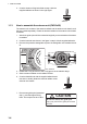
. INSTALLATION • For X-band radar, if it is necessary to lay down the radiator before you fasten it to the antenna unit, lay it down with the waveguide up, to prevent damage to the cylinder that surrounds the waveguide. Lay down radiator with waveguide facing upward. Waveguide Cylinder • If the de-icer is installed, a two-pole breaker (supplied locally) must also be installed. Note: For more information, please refer to IMO SN/Circ.271 "Guidelines for the installation of shipborne radar equipment. 1.
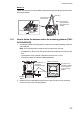
1. INSTALLATION 5. Coat the Antenna fixing bolts fixed at step 4 with the supplied adhesive as shown in the right figure. Adhesive 1.1.3 How to assemble the antenna unit (FAR-2x58) The antenna unit consists of the antenna radiator and the antenna unit chassis, and they are packed separately. Fasten the antenna radiator to the antenna unit chassis as follows: 1. Attach two guide pins which are attached originally to the underside of the antenna radiator. 2.
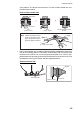
1. INSTALLATION Antenna radiator Waveguide Radiator bracket Guide pin Hex bolt (M8×40), 8 pcs. O-ring 1.1.4 How to hoist the antenna unit (FAR-2x18/2x28/2x38) The antenna unit may be assembled before hoisting it to the mounting platform. Attach lifting belt slings to the “Radiator Bracket”, NOT the antenna radiator, as shown in the figure below. Also, hoist the antenna unit slowly. Hoisting swiftly may cause a damage to the antenna radiator or damage the radiator chassis.
1. INSTALLATION Method 2 Fasten belt sling to a shackle, pass belt sling around radiator bracket and fasten other end of belt sling to other shackle. Belt sling Bow side UP Shackle (left, right) Radiator bracket Lifting fixture (ø20) 1.1.5 Note: Pass belt sling around the Radiator bracket. How to hoist the antenna unit (FAR-2x58) The antenna unit may be assembled before hoisting it to the mounting platform. Do one of the following to hoist the antenna unit.
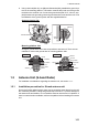
1. INSTALLATION Method 2 Fasten one belt sling to both shackles, and pass the other belt sling around the stern side of the radiator. Belt sling Bow side of the antenna unit Note: Pass the belt sling around the stern side of the radiator. Lifting Fixture Shackle 1.1.6 How to fasten the antenna unit to the mounting platform (FAR2x18/2x28/2x38) 1. Construct a suitable mounting platform referring to the outline drawing at the end of this manual.
1. INSTALLATION 3. Place the antenna unit on the platform, then orient the unit so the bow mark on its base is facing the ship’s bow. Note: When the antenna unit is placed on the platform, make sure that the platform is not inclined. FRONT Bow mark (▼) 4. Insert four sets of hex bolts (M1270) attached the seal washers to the mounting holes of the antenna chassis. Lift the antenna chassis slightly then insert the bolts attached the insulation sheets.
1. INSTALLATION of the platform. The torque must be 49 N•m. For how to fasten double nuts, see the following procedure. How to fasten double nuts Seal washer 1 3 Flat washer 2 Nut1 (Torque: 57 N•m) Nut2 (Torque: 49 N•m) Nut1&2: Simultaneous work as below. Note: Fasten the double nuts as shown in the figure to the right. Use spanners with a length of approx. 200 mm. Nut1: Fasten Nut2: Fix in place 7.
1. INSTALLATION Mounting platform side Arrange a ground terminal as close as possible to antenna unit. There are two methods to connect the ground wire for mounting platform side. Method 1 Method 2 Adhesive Hex bolt Ground wire Hex bolt Spring washer Flat washer Mounting Platform Adhesive Ground wire Flat washer Hex bolt Flat washer Spring washer Hex nut Mounting Platform Welding 1.1.7 How to fasten the antenna unit to the mounting platform (FAR2x58) 1.
1. INSTALLATION 8. Using a hex bolt (M625), nut (M6) and flat washer (M6), establish the ground system on the mounting platform. The location must be within 340 mm of the ground terminal on the antenna unit. Connect the ground wire (RW-4747, 340 mm, supplied) between the grounding point and ground terminal on the antenna unit. Coat the hardware of the ground system with the supplied adhesive.
1. INSTALLATION Mast for DF, etc. OK S-band Antenna Mount the antenna unit directly on the mast or on the platform, as near as possible to center of the mast. 1.2.2 Excessive movement (pitching) How to assemble the antenna unit The antenna unit consists of the antenna radiator (w/antenna support) and the antenna unit chassis, and they are packed separately. Fasten the antenna radiator to the antenna unit chassis as follows: 1.
1. INSTALLATION 4. Fasten the antenna radiator to the radiator bracket from the bottom of the bracket with the eight hex bolts, spring washers and flat washers. The torque must be 49 N•m. Bracket Flat washers Spring washers Hex bolt Coat with adhesive M12 bolts (eight places) 5. Coat the bolt heads fastened at step 4 with the supplied adhesive as shown in the figure to the right. Adhesive 6. Connect the coaxial cable from the antenna unit to the rotary joint. The torque must be 25 N•m.
1. INSTALLATION Note 2: Set the screw for the safety rope to come to the left when viewed from the front side of the antenna. 1.2.3 How to hoist the antenna unit The antenna unit may be assembled before hoisting it to the mounting platform. Attach lifting belt slings to the “Antenna Support”, NOT the antenna radiator, as shown in the figure below. Also, hoist the antenna unit slowly. Hoisting swiftly may cause a damage to the antenna radiator or damage the radiator chassis.
1. INSTALLATION Method 2 Fasten the belt sling to a shackle, pass the belt sling around the antenna support and fasten the other end of the belt sling to the other shackle. Belt sling Bow side UP Shackle (left, right) Antenna support Lifting fixture (ø20) 1.2.4 Note: Pass the belt sling around the Antenna Support. How to fasten the antenna unit to the mounting platform 1. Construct a suitable mounting platform referring to the outline drawing at the back of this manual.
1. INSTALLATION Use two nuts. Over 15 mm Mounting platform Be careful not to get welding splatter on nuts, bolts, etc. on the mounting platform. The reinforcement ribs must be installed diagonally. Thickness: Over 6 mm Diameter: Over 250 mm Bottom of platform Seal washer Chassis Corrosion proof rubber mat Platform Flat washer Spring washer M12×70 (eight places) Adhesive Two nuts (Torque: 49 N•m) 5.
1. INSTALLATION Mounting platform side Arrange ground terminal as close as possible to antenna unit. There are two methods to connect ground wire for mounting platform side. Method 1 Method 2 Hex bolt Ground wire Hex bolt Spring washer Flat washer Mounting Platform Ground wire Flat washer Hex bolt Flat washer Spring washer Hex nut Adhesive Adhesive Mounting Platform Welding 1.
1. INSTALLATION • A magnetic compass will be affected if the control unit is placed too close to the magnetic compass. Observe the compass safe distances in the SAFETY INSTRUCTIONS to prevent interference to the compass. Usage Notice The control units can turn the power on/off. However, to prevent accidental power on, always turn the system off at the ship's main for the processor unit and the power supply unit BEFORE conducting maintenance, service or wiring cables. 1.4.
1. INSTALLATION Self tapping screw (Ø5×20, 4 pcs) Cutout should be located on the top side. KB fixture 3. Attach a ground wire (IV-1.25sq, supplied locally) to the ground terminal at the bottom of the unit. Ground screw* * : Use the screw that is preattached to the ground terminal. Ground wire 4. Secure the control unit the KB fixture, using four binding screws (M520, supplied). 5. Attach four bolt hole caps (supplied).
1. INSTALLATION How to mount the unit flush with mounting surface 1. Drill four mounting holes of 5 mm diameter referring to the outline drawing at the back of this manual. 2. Fix the control unit with four screws (M4) from the underside of the desktop. (The M4 screws with a sufficient length for the thickness of the desktop should be provided locally.) Control Unit RCU-014 F1 F2 F3 F4 Control Unit RCU-015/RCU-016 1.
1. INSTALLATION 4. Set the unit to the mounting location so that the stud bolts on the bottom of the unit are inserted to the pilot holes. 5. Fasten the four wind nuts (supplied) to the stud bolts from the rear side of the mounting surface. Wing nut (4 pcs) 1.4.2 Flush mount Installation Note: For flush mounting in a panel, the mounting surface must be flat. Do not install the unit on an uneven surface.
1. INSTALLATION 4. Screw the wing screw to each mounting plate and then insert hex. bolt to each wing screw. 5. Fasten each wing screw and then fasten the hex. nuts as shown in figure below. RCU-015/016 RCU-014 Side view of control units Flush mount, fixed at font (for RCU-031) Note: For flush mounting, select a location where the surface is flat. 1. Make a mounting hole and drill four pilot holes in the mounting location, referring to the outline drawing at the back of this manual. 2.
1. INSTALLATION 1.4.3 Installation of RCU-016 connected with RCU-014 1. Pass the cable from RCU-016. 2. Connect the RCU-016 cable connector to J502. 3. Clamp the copper part of the cable with the cable clamp. How to change the cable entry of RCU-015/016 To change the cable entry from the side (default) to the bottom, modify the unit as shown in the following procedure. 1. Turn the chassis upside-down and remove four screws (M38) to open the back cover. 2.
1. INSTALLATION 1.5 Power Supply Unit This unit can be installed on a bulkhead, wall or on the floor. 1.5.1 Installation considerations Keep in mind the following points when selecting a location. • Locate the processor unit away from heat sources because of heat that can build up inside the cabinet. • Select a location where the vibration is minimal. • Locate the equipment away from places subject to water splash and rain.
1. INSTALLATION 1.5.2 How to install the processor unit Use four bolts (M6, local supply) to fasten the processor unit. For bulkhead mounting, fasten two bolts for the lower notches, leaving 5 mm of thread exposed from the bolt head. Set the notches of the processor unit on the two bolts, then fasten two bolts for the upper bolt holes. Then secure the processor unit in place with all four bolts fastened tightly. Bolt holes Notches Note: For bulkhead installations, the cable entry must face the deck.
1. INSTALLATION • Install the processor unit on the floor, or on a bulkhead with the following direction. For bulkhead, the cable entry must face the deck. OK Installation on a bulkhead OK Installation on a floor : Cable entry • Connect the ground wire (IV-8sq, local supply) between the earth terminal on the chassis and the ship’s earth, using the supplied crimp-on-lug FV2-M3 BLU. 1.6.2 How to install the processor unit Use four bolts (M6, local supply) to fasten the processor unit.
1. INSTALLATION 1.7 Transceiver Unit The transceiver unit is required for TR-DOWN Radar. Installation considerations Keep in mind the following points when selecting a location. • Locate the unit away from heat sources because of heat that can build up inside the cabinet. • Locate the equipment away from places subject to water splash and rain. • Leave sufficient space at the sides and rear of the unit to facilitate maintenance.
1. INSTALLATION How to install the Intelligent Hub 1. Use two binding screws (M36, supplied) to attach the cable clamp (supplied) to the bottom of the HUB-3000. Binding screw (M3×6, 2 pcs) Cable clamp Bottom view 2. Fasten four self-tapping screws (420, supplied) to secure the unit. : Screw holes 1.9 Switching Hub (option) Use the HUB-100 to connect sensor networks. This network cannot be connected to the shipborne LAN network.