
Users Manual Part 2


1. INSTALLATION
1-18
• A magnetic compass will be affected if the control unit is placed too close to the
magnetic compass. Observe the compass safe distances in the SAFETY IN-
STRUCTIONS to prevent interference to the compass.
Usage Notice
The control units can turn the power on/off. However, to prevent accidental power on,
always turn the system off at the ship's main for the processor unit and the power sup-
ply unit BEFORE conducting maintenance, service or wiring cables.
1.4.1 Desktop installation
For desktop installation, the unit can be laid flat or tilted.
How to mount the unit tilted
<RCU-014/015/016>
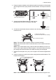
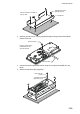
1. Fit the KB fixing plate (in FP03-09850 for RCU-014, in FP03-09860 for RCU-015/
016) to the bottom of the control unit.
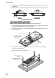
2. Attach the rubber foots (three for RCU-014, two for RCU-015/016) to the bottom
of the control unit as shown in the following figure.
3. Install the control unit at the desired location with self-tapping screws (local sup-
ply).
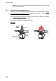
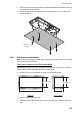
Side view of control units
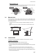
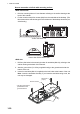
<RCU-031>
The control unit can be mounted with the KB fixture, which mounts the unit at an angle.
1. Drill four pilot holes in the mounting location for mounting screws, referring to the
outline drawing at the back of this manual.
2. Secure the KB fixture (supplied) to the mounting location, using four self tapping
screws (520, supplied).
Note: Secure the KB fixture so that the cutout is located on the top side.
KB fixing plate
Rubber Foot