
Users Manual Part 2


1. INSTALLATION
1-19
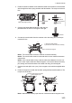
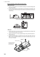
3. Attach a ground wire (IV-1.25sq, supplied locally) to the ground terminal at the
bottom of the unit.
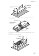
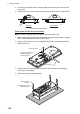
4. Secure the control unit the KB fixture, using four binding screws (M520, sup-
plied).
5. Attach four bolt hole caps (supplied).
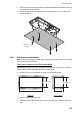
Self tapping screw
(Ø5×20, 4 pcs)
KB fixture
Cutout should be located on
the top side.
Ground wire
*
: Use the screw that is
preattached to the
ground terminal.
Ground screw*
Binding screw
(M5×20, 4 pcs)
Bolt hole cap
(4 pcs)