
Users Manual Part 2


1. INSTALLATION
1-22
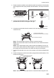
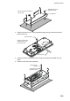
4. Screw the wing screw to each mounting plate and then insert hex. bolt to each
wing screw.
5. Fasten each wing screw and then fasten the hex. nuts as shown in figure below.
Side view of control units
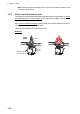
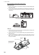
Flush mount, fixed at font (for RCU-031)
Note: For flush mounting, select a location where the surface is flat.
1. Make a mounting hole and drill four pilot holes in the mounting location, referring
to the outline drawing at the back of this manual.
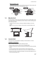
2. Attach a ground wire (IV-1.25sq, supplied locally) to the ground terminal at the
bottom of the unit.
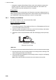
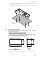
3. Set the unit to the mounting hole, then secure the unit with four self-tapping
screws (520, supplied).
4. Attach four bolt hole caps (supplied).
RCU-014
RCU-015/016
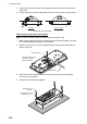
Ground wire
*
: Use the screw that is
preattached to the
ground terminal.
Ground screw*
Self tapping screw
(Ø5×20, 4 pcs)
Bolt hole cap
(4 pcs)