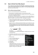
3. TARGET TRACKING (TT) 3.5 How to Enter Own Ship Speed The TT requires own ship's speed and heading data. The speed can be STW, SOG or echo-referenced speed (based on 3 max. stationary objects). Manual input is also possible. For automatic or manual input, see section 1.11. For echo-referenced speed input follow the procedure below. 3.5.1 Echo-referenced speed input The use of echo-referenced speed is recommended when: • The speed log is not operating properly or not connected to the radar.
3. TARGET TRACKING (TT) Notes on speed input by reference target • Reference targets are only used for the calculation of true speed. • Do not use reference target generated true speed to calculate relative speed. Relative speed data is not accurate because response to speed change is slow, hampering the TT's ability to accurately judge the possibility of collision. • Select a stationary target as a reference target to calculate own ship speed as ground tracking speed.
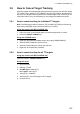
. TARGET TRACKING (TT) 3.6 How to Cancel Target Tracking When the number of tracked targets reaches maximum capacity, the alert box shows [TT TARGET FULL (MAN)] or [TT TARGET FULL (AUTO)], based on the selected TT mode. No new targets can be acquired until a tracked target is lost or tracking is canceled. When this occurs, cancel tracking for non-dangerous targets as required. 3.6.
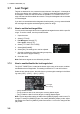
3. TARGET TRACKING (TT) 3.7 Lost Target Targets not detected in nine consecutive scans become “lost targets”. A lost target is shown in the display with a flashing red "". Flashing stops after lost target alert is acknowledged. Further, the alert box shows the indication "TT TARGET LOST" in orange characters and the audible alert sounds. The symbol disappears when the alert is acknowledged.
3. TARGET TRACKING (TT) 3.8 TT Symbols and Attributes The TT symbols used in this equipment are compliant with IEC62288. For details regarding the symbols and their meanings, see "TT/AIS symbols" on page AP-34. 3.8.1 How to adjust symbol brilliance Note: Each color scheme (palettes PLT1 to PL4) can be adjusted individually. For how to select a color scheme, see section 1.46.3. 1. Open the menu. 2. Select [9 INITIAL SETTINGS]. 3. Select [2 BRILL]. The [BRILL] menu appears. 4.
3. TARGET TRACKING (TT) 3.8.3 How to set the symbol size (C-types only) C-types radar can show TT symbols in small or large size. You can change the size with the following procedure. 1. Open the menu. 2. Select [5 TT•AIS]. 3. Select [3 TT•AIS SYMBOL]. 4. Select [0 NEXT] to show the second page of the menu. 5. Select [4 TT SYMBOL SIZE]. 6. Select [SMALL] or [LARGE] as required. 7. Close the menu 3.8.
3. TARGET TRACKING (TT) Note: You can also left-click the TT target’s data in the information box (see section 3.9.2) to show the editing window. 2. If the [INPUT TT LABEL] window is shown, press F3 to show the [TT CUSTOM SELECT] window. 3. Referring to the following table, select the item you want to edit. Menu item [LABEL] Description Assigns a number to the target, other than the pre-assigned TT number. Note 1: The value set here appears in front of the name (assigned at [TGT NAME]).
3. TARGET TRACKING (TT) 7. Referring to the following table, select the item you want to edit. Menu item [SMBL COLOR] [SMBL SHAPE] [TRACK COLOR] [TGT NAME] Description Change the symbol color for the selected preset. Change the symbol shape for the selected preset. Change the track color for the selected preset. Assign/change the target name. Note: The software keyboard appears inside the editing window. See section 1.5.3 for how to use the keyboard. 8. Right-click to close the window. 3.
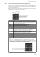
3. TARGET TRACKING (TT) 3.9.2 How to show target data in the data display area Place the cursor on a desired tracked target and left-click, or press the ACQ key. The target’s symbol is surround with a broken square and the selected TT target’s data is shown in the data display area. Note: This feature requires [2 TGT DATA/ACQ SETTING] on the second page of the [CURSOR] menu to be set as [ANY] or [TT ONLY]. Target No.
3. TARGET TRACKING (TT) The number of TT data that can be displayed at one time in the information box depends on your settings for [7 INFORMATION BOX] (see section 1.48). To remove the target data, place the cursor on a desired tracked target and press the TARGET CANCEL key, left-click. The select target’s data is removed from the data display area. 3.9.
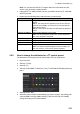
3. TARGET TRACKING (TT) How to sort the target list 1. With the target list displayed, place the cursor on the sorting method indication to the right of [SORT] ("CPA" in the example below). The indication is highlighted. 2. Spin the scrollwheel to select the sort method, referring to the table below, then left-click. Sorting method Filter method Sorting method [CPA] [TCPA] [BCR] [BCT] [RANGE] [SPEED] [NAME] Description Targets are sorted in order from closest to farthest CPA.
3. TARGET TRACKING (TT) 3.10 Vector Modes Target vectors can be displayed relative to own ship’s heading (Relative) or North (True). Note: IMO recommends the use of true vector mode in sea stabilization or relative vector mode for collision avoidance. 3.10.1 Description of vectors Stabilization modes It is important to select the optimum stabilization mode for the radar display.
3. TARGET TRACKING (TT) Ground stabilization and sea stabilization Target vectors can be ground stabilized or sea stabilized in the True Motion mode. To select speed over the ground or speed through the water data, open the page from the menu. Select for ground stabilization or for sea stabilization. The vector mode indication shows the stabilization mode in the true motion as [TRUE-G] or [TRUE-S].
3. TARGET TRACKING (TT) 3.10.2 Vector mode and vector length Vectors can be displayed in true or relative modes. Vector lengths can be set between 30 seconds and 60 minutes. The vector tip shows an estimated position of the target after the selected vector time elapses. It can be valuable to extend the vector length to evaluate the risk of collision with any target.
3. TARGET TRACKING (TT) 3.11 Past Position Display The past position display shows equally time-spaced dots marking the past positions of any targets being tracked. A new dot is added every minute (or at other preset time intervals) until the preset number is reached. If a target changes its speed, the spacing will be uneven. If it changes the course, its plotted course will not be a straight line. Past position orientation, true or relative, is controlled with [TRAIL MODE] in the [TRAIL] context menu.
3. TARGET TRACKING (TT) 3.11.3 How to change the color of TT tracks (C-types only) You can change the color of the TT tracks with the following procedure. 1. Open the menu. 2. Select [5 TT•AIS]. 3. Select [3 TT•AIS SYMBOL]. 4. Select [3 TT SYMBOL COLOR]. 5. Select the desired color you want to show the TT tracks in. 6. Close the menu. 3.12 Set and Drift Set, the direction in which a water current flows, can be manually entered in 0.1-degree steps.
3. TARGET TRACKING (TT) 3.13 Collision Alarm (CPA, TCPA) This radar calculates CPA and TCPA by using own ship and relative target positions. The TT continuously monitors the predicted range at the Closest Point of Approach (CPA) and predicted time to CPA (TCPA) of each TT. When the predicted CPA of any TT becomes smaller than a preset CPA range and its predicted TCPA less than a preset TCPA limit, the audio alarm sounds and "TT DANGER OF COLLISION" appears (in red, flashing) in the Alert Box.
3. TARGET TRACKING (TT) 3.13.2 How to acknowledge the TT collision alarm Press the ALARM ACK (RCU-014) or ALERT ACK (RCU-031) key on the control unit, or select the [ALERT] box with the trackball then left-click to acknowledge the alarm and silence the buzzer. The alert "TT DANGER OF COLLISION" remains in the Alert Box until the dangerous situation is gone or you intentionally terminate target tracking. The symbol and vector stop flashing and are displayed in a solid red color.
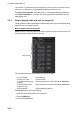
3. TARGET TRACKING (TT) 3.14.2 How to activate the first acquisition zone (AZ1) The No. 1 acquisition zone is available between 3 NM and 6 NM and can have a width between 0.5 NM and 1 NM. The TT/AIS acquisition zone’s lines are white and dashed so as to distinguish them from the radar target alarm. The procedure below shows how to set AZ1, using the example at the bottom of the page. 1. Place the cursor on the [1:] indication at the bottom-right of the screen, then left-click.
3. TARGET TRACKING (TT) 3.14.4 How to sleep/deactivate an acquisition zone 1. Select the appropriate [AZ] box. 2. Sleep, or deactivate, the acquisition zone, as explained below: Sleeping the acquisition zone Left-click the box several times until the indication shows "SLEEP". Deactivating the acquisition zone Highlight the box with the cursor, the press and hold the left-button until the AZ box becomes blank.
3. TARGET TRACKING (TT) 3.14.8 How to set acquisition zone shape and stabilization The shape of the No. 2 acquisition zone can be a sector or a polygon having up to 10 points. (The shape of the No.1 acquisition zone is always a sector.) 1. Open the menu. 2. Select [5 TT•AIS]. 3. Select [2 ACQUISITION ZONE]. 4. Select [5 AZ POLYGON]. 5. Select the appropriate setting.
3. TARGET TRACKING (TT) 3.15 Trial Maneuvers (IMO-types only) The trial maneuver feature simulates the effect of own ship's movement against all tracked targets, without interrupting the updating of target information. It is available for use with the TT and AIS functions. For more accurate results, use sea stabilization (water tracking). 3.15.1 Types of trial maneuvers There are two types of trial maneuvers: dynamic and static.
3. TARGET TRACKING (TT) Static trial maneuver The static trial maneuver shows the relationship between your ship and tracked targets at the completion of the trial maneuver. The expected position of TTs at the end of the trial maneuver are shown on the display. By shortening and extending the trial time you can find the safe time to make a maneuver. Thus, the static trial maneuver will be convenient when you wish to know the maneuver result immediately.
3. TARGET TRACKING (TT) Setting example for [3 TRIAL SPEED RATE] Trial speed rate 5 kn, 0.15 kn/s 10 kn, 0.45 kn/s 0.45 kn/s (Second setting) 0.15 kn/s (First setting) 5 kn (First setting) 10 kn (Second setting) Trial maneuver speed Setting example for [4 TRIAL TURN RATE] Trial turn rate 5 kn, 1.5 °/s 10 kn, 4.5 °/s 4.5 °/s (Second setting) 1.5 °/s (First setting) 5 kn (First setting) 10 kn (Second setting) Trial maneuver speed 10. Close the menu 11.
3. TARGET TRACKING (TT) 15. Select the delay time indication, then left-click. 16. Spin the scrollwheel to set the amount of delay. This is the time after which own ship takes a new situation, not the time the simulation begins. Change the delay time according to own ship loading condition, etc. The time indication depends on trial type: [DYNAMIC]: The position of your ship and TTs is displayed every 30 seconds and updating occurs every 0.5 seconds.
3. TARGET TRACKING (TT) 3.16 TT System Messages There are four main reasons the TT may trigger the audio and visual alerts: • Collision alarm • Acquisition zone alert • Lost target alert • Target capacity You can acknowledge visual alerts and silence the audio alerts with one of the following methods: • Press the ALARM ACK (RCU-014) or ALERT ACK (RCU-031) key • Click the [ALERT] box, at the bottom-right of the screen. • Click the alert in the [ALERT LIST].
3. TARGET TRACKING (TT) 3.17 TT Simulation Mode You can simulate the risk of a collision by using the TT simulation mode. This function can be used for familiarization training for your crew. The simulation can be terminated at any time by pressing the STBY TX key. 1. Open the menu. 2. Select [9 INITIAL SETTINGS]. 3. Select [7 TESTS]. 4. Select [4 TT SIMULATION MODE]. The normal operation is suspended then three simulated targets appear on the display.
3. TARGET TRACKING (TT) 3.18 Criteria for Tracking Target Selection The FURUNO TT video processor detects targets in midst of noise and discriminates radar echoes on the basis of their size. Target whose echo measurements are greater than those of the largest ship in range or tangential extent are usually land and are displayed only as normal radar video.
3. TARGET TRACKING (TT) The true course and speed of own ship are computed from own ship's gyro and speed inputs, and the resulting course and speed of each tracked target is easily computed by vector summing of the relative motion with own ship’s course and speed. The resulting true or relative vector is displayed for each of the tracked targets. This process is updated continually for each target on every scan of the radar.
3. TARGET TRACKING (TT) Tracking continues if a return echo is received at least once in nine antenna rotations. However, the fewer the return echoes the lower the accuracy. If no return echo is received within nine antenna rotations the target is declared a lost target. Second trace echoes When the radar beam is super refracted, strong echoes may be received at such long ranges that they appear on a different timebase sweep than the transmitted pulse. This gives an incorrect range indication.
4. AIS OPERATION An AIS transponder can be connected to this radar to overlay AIS targets on the radar display. The radar can store up to 1,200 AIS targets in its storage buffer. When this buffer becomes full of AIS targets, the Alert "AIS CAPACITY FULL" is generated to alert you to a full storage buffer. The storage buffer contains automatic dead reckoning for all AIS targets, which is based on reported Speed Over the Ground (SOG) and Course Over the Ground (COG).
4. AIS OPERATION There can be several hundreds or several thousands of AIS targets, and of those only a few will be significant for your ship. To remove unnecessary AIS targets from the radar display, the feature "active and sleeping AIS targets" is available. Initially any new AIS target received by an AIS transponder is not active (="sleeping"). Such sleeping targets are shown with a small triangle. The operator can pick any AIS target and change it from sleeping to active (see section 4.5 and section 4.
4. AIS OPERATION 4.2 How to Select the AIS Display Mode AIS display mode • [DISP OFF]: AIS symbols are hidden. • [DISP FILT]: Only filtered AIS targets are displayed. • [DISP ALL]: All AIS symbols are displayed. To disable the AIS function, put the cursor on the AIS display mode indication, then long right-click. The AIS display mode indication shows [FUNC OFF] when the AIS function is disabled. Note: The AIS mode indication is hidden when [SIMPLE] display mode is used.
4. AIS OPERATION 4.4 How to Use the AIS Display Filter If there are too many AIS targets on the screen you may wish to remove unnecessary ones. You can remove sleeping targets class A/B by distance from own ship, speed and class. For example, you might want to remove slow moving targets, as they normally do not require close monitoring. 1. Open the menu. 2. Select [5 TT•AIS]. 3. Select [4 AIS].
4. AIS OPERATION 6. Referring to the table below, select the appropriate filter. Filter type [MAX RANGE] [MIN SHIP SPEED] [EXCEPT CLASS B]* [EXCEPT BASE STATION] [EXCEPT PHYSICAL ATON] [EXCEPT VIRTUAL ATON] Definition Any sleeping AIS targets class A/B beyond the range set here will not be shown. Any sleeping AIS targets class A/B slower than this setting will not be shown. Select [ON] to remove sleeping AIS targets class B. Select [ON] to remove the BASE STATION symbol.
4. AIS OPERATION Activate a AIS target with the trackball Put the cursor on the symbol of the AIS target to activate, then click. SOG (Speed Over Ground) and COG (Course Over Ground) vector *1 *1 4.5.2 Vector shows STW (Speed Thru Water) and CTW (Course Thru Water) when water tracking mode is selected at the radar. Turning direction (ROT) Heading line *2 *2 If there is no heading data available, the heading line is not displayed.
4. AIS OPERATION How to enable/disable the AIS auto activate function Use the [CPA AUTO ACTIVATE] box at the bottom right corner to enable or disable the AIS auto activate function. OFF OFF CPA auto-activate setting Note: The AIS CPA setting is hidden when [SIMPLE] display mode is used. To change the setting in [SIMPLE] mode, first restore [NORMAL] display mode, adjust the setting, then return to [SIMPLE] mode. See section 1.9 for how to change the display mode. 1.
4. AIS OPERATION 4.6.2 How to sleep all AIS targets 1. Open the menu. 2. Select [5 TT•AIS]. 3. Select [5 AIS]. 4. Select [2 SLEEP ALL TARGETS]. 5. Select [YES] or [NO] as appropriate. 6. Close the menu. 4.7 How to Set Up For a Voyage At the start of a voyage, following five items must be input from the [VOYAGE DATA] menu: navigational status, ETA, destination, draught and crew. 4.7.
4. AIS OPERATION Nav Status No. 06 07 08 09 10 11 12 13 14 15 Meaning AGROUND ENGAGED IN FISHING UNDER WAY SAILING RESERVED FOR HIGH SPEED CRAFT (HSC) RESERVED FOR WING IN GROUND (WIG, FOR EXAMPLE, HYDROFOIL) POWER-DRIVEN VESSEL (AHEAD/ASTERN) POWER-DRIVEN VESSEL (AHEAD/ALONGSIDE) RESERVED FOR FUTURE USE SART ACTIVE UNDEFINED 7. Select [3 ETA]. 8. Spin the scrollwheel to set the estimated day of the month to arrive, then left-click. Currently selected digit is highlighted by the cursor.
4. AIS OPERATION 4.8 How to Display AIS Target Data You can display an AIS target’s data by selecting it on the display, when the AIS function is set for [DISP FILT] or [DISP ALL]. 4.8.1 AIS pop-up information The AIS pop-up shows abbreviated AIS data (Vessel name, COG, SOG, CPA, TCPA and destination*) for the selected AIS target. Simply put the cursor on the AIS target to show the pop-up. *: Destination appears for Class A targets only.
4. AIS OPERATION 4.8.2 How to display basic AIS target data Place the cursor on a desired AIS target and press the TGT ACQ key, or left-click. The target is highlighted with a square box and the selected AIS target’s data is shown in AIS target data box inside the information box, on the right side of the screen. Unavailable data appears with the indication "missing". Note 1: This feature requires [2 TGT DATA/ACQ SETTING], on the second page of the [CURSOR] menu, to be set as [ANY] or [AIS ONLY].
4. AIS OPERATION 4.8.3 How to display expanded AIS target data The expanded AIS data display provides additional information about an AIS target, including call sign, IMO No., etc. To display expanded AIS data, show the basic data for a target, then left-click the target data display. The expanded data appears.
4. AIS OPERATION 4.9 How to Change AIS Symbol Attributes To change the brilliance, size and color of AIS symbols follow the appropriate procedure in this section. 4.9.1 How to adjust the AIS symbol brilliance Note: The brilliance of the AIS symbols can be adjusted from the [PLT] button on the Instant Access bar™. See section 1.46.1. 1. Open the menu. 2. Select [9 INITIAL SETTINGS]. 3. Select [2 BRILL]. The [BRILL] menu appears. 4. Select [0 NEXT] to show the next menu page. 5. Select [8 AIS SYMBOLS].
4. AIS OPERATION 4.9.3 How to change the color of the ATON symbol 1. Open the menu. 2. Select [5 TT•AIS]. 3. For IMO-types, select [4 TT•AIS SYMBOL]. For C-types, select [3 TT•AIS SYMBOL]. 4. For IMO-types, select [3 ATON SYMBOL COLOR]. For C-types, select [6 ATON SYMBOL COLOR]. 5. Select the appropriate color, then left-click. 6. Close the menu. 4.9.4 How to change the size of the AIS symbol 1. Open the menu. 2. Select [5 TT•AIS]. 3. For IMO-types, select [4 TT•AIS SYMBOL].
4. AIS OPERATION Note: You can also right-click an AIS target to open the [CUSTOMIZE AIS DISPLAY] menu with the selected vessel’s MMSI field completed. 8. Select [3 CUSTOMIZE SHIP NAME]. 9. Referring to section 1.5.3, enter a custom name for the vessel. If [6 DISP CUSTOMIZED NAME] is set to [ON], the name set here appears near the AIS symbol. If [DISP CUSTOMIZED NAME] is set to [OFF] and the vessel is transmitting its name in the AIS data, the received name appears near the AIS symbol. 10.
4. AIS OPERATION 4.9.7 How to show/hide the customized AIS name (C-types only) You can display a vessel’s name below the corresponding AIS symbol. 1. Open the menu. 2. Select [5 TT•AIS]. 3. Select [4 AIS]. 4. Select [0 NEXT]. 5. Select [6 DISP CUSTMIZED NAME]. 6. To show the name, select [ON]. The name set at section 4.9.5 appears below the icon for the selected vessel. To hide the name, select [OFF].