OPERATOR'S MANUAL Bottom Discrimination Sounder Model BBDS1 www.furuno.
IMPORTANT NOTICES General • This manual has been authored with simplified grammar, to meet the needs of international users. • The operator of this equipment must read and follow the descriptions in this manual. Wrong oper-ation or maintenance can cancel the warranty or cause injury. • Do not copy any part of this manual without written permission from FURUNO. • If this manual is lost or worn, contact your dealer about replacement.
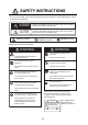
SAFETY INSTRUCTIONS The user and installer must read the appropriate safety instructions before attempting to install or operate the equipment. WARNING Indicates a potentially hazardous situation which, if not avoided, could result in death or serious injury. CAUTION Indicates a potentially hazardous situation which, if not avoided, may result in minor or moderate injury.
SAFETY INSTRUCTIONS Safety instructions for the installer WARNING CAUTION The transducer cable must be handled carefully, following the guidelines below. Do not open the equipment. Only qualified personnel should work inside the equipment. ● Turn off the power at the main switchboard before beginning the installation. ● ● Fire or electrical shock can result if the power is left on. Keep fuels and oils away from the cable. Locate the cable away from chemicals.
TABLE OF CONTENTS FOREWARD ....................................................................................................................v SYSTEM CONFIGURATION ..........................................................................................vi EQUIPMENT LIST .........................................................................................................vii 1. MOUNTING ...............................................................................................................1 1.
FOREWARD A Word to the Owner of the BBDS1 Congratulations on your choice of the BBSD1 Bottom Discrimination Sounder. We are confident you will see why the FURUNO name has become synonymous with quality and reliability. Since 1948, FURUNO Electric Company has enjoyed an enviable reputation for innovative and dependable marine electronics equipment. This dedication to excellence is furthered by our extensive global network of agents and dealers.
SYSTEM CONFIGURATION Bottom Discrimination Sounder BBSD1 NavNet 3D/ TZtouch series MFD8/12 MFDBB, TZT9/14 NavNet 3D/ TZtouch series HUB-101 MFD8/12 MFDBB, TZT9/14 MFD8/12 MFDBB, TZT9/14 Rectifier PR-62 Matching Box MB-1100 12-24 VDC 100/110/220/230 VAC, 1ø, 50/60 Hz Transducer 520-5PSD 525-5PWD 520-5MSD Speed/temperature sensor ST-02MSB ST-02PSB Triducer 525STID-MSD 525STID-PWD Temperature sensor T-02MTB T-02MSB T-03MSB *: HUB-101 may be connected to 3 sets of MFB8/12/MFDBB vi Transducer 50/20
EQUIPMENT LIST Standard supply Name Bottom Discrimination Sounder Spare Parts Installation Materials Type BBDS1 Code No. Qty - 1 SP02-05201 CP02-08700 001-007-860 000-017-040 1 set 1 set Remarks Fuse See Packing List Optional supply Name Matching Box Cable Assy Type MB-1100 MOD-Z072-020+ MOD-Z072-100+ 525STID-MSD 525STID-PWD 520-5PSD 520-5PWD 520-5MSD 50/200-1T 50/200-12M ST-02MSB ST-02PSB Code No.
1. MOUNTING 1.1 Bottom Discrimination Sounder CAUTION Do not apply paint, rust protection, etc, to coated surface parts of the unit. These may damage the coated surface areas. Be especially careful not to apply chemicals to the coated connectors. The Bottom Discrimination Sounder can be installed on a desktop, deck or on a bulkhead. When selecting a mounting location for the Bottom Discrimination Sounder, keep the following in mind: • Locate the unit away from areas where rain and splash can occur.
1. MOUNTING 1.2 Transducer 520-5PSD, 520-5MSD 1.2.1 Mounting location The performance of this sounder is directly related to the mounting location of the transducer, especially for high-speed cruising. The installation should be planned in advance, keeping the standard cable length and the following factors in mind: • When the boat has a keel, the transducer should be at least 15-30 cm (5.9” - 11.8”) away from it. Typical thru-hull mountings are shown in the figure on the next page.
1. MOUNTING 1.2.2 Acceptable mounting locations Deep V-hull * Position 1/2 to 1/3 length of the hull from stern. * 15-30 cm from keel line (inside first lifting strakes). High speed V-planning hull * Within the submerged bottom area * Deadrise angle within 15° 1.2.3 Installation Procedure 1. With the boat hauled out of the water, mark the location selected for mounting the transducer on the bottom of the hull.
1. MOUNTING low and make the entire surface as smooth as possible to provide an undisturbed flow of water around the transducer. The fairing block should be smaller than the transducer itself to provide a channel to divert turbulent water around the sides of the transducer rather than over its face. BOW Hole for stuffing tube Upper half Lower half Saw along slope of hull 2.
1. MOUNTING cm (20.0”) Flat Hull 1.3.1 Deep-V Hull Installation for flat hulls A suitable mounting location is at least 50 cm (20.0”) away from the engine and where the water flow is smooth. 1. Drill four pilot holes in the mounting location. 2. Attach the transducer to the bracket with self-tapping screws (supplied). 3. Adjust the transducer position so the transducer faces right to the seabed.
1. MOUNTING M5x20 M5x20 No. 2 1.3.3 M5x14 Transducer preparation Before putting the boat in water, wipe the face of the transducer thoroughly with a detergent liquid soap. This will lessen the time necessary for the transducer to have good contact with the water. Otherwise the time required for complete "saturation" will be longer, and the performance will be reduced. Note: Do not paint the transducer surface. Performance will be affected. 1.
1. MOUNTING Locknut Face “notch” toward bow. Flange nut 51 (2.0”) Coat with silicone l t 123mm (4.8”) Brim ø77 (3 0”) 1.5 Optional Temperature Sensors 1.5.1 Transom mount temperature sensor T-02MTB • Fix the cable at a convenient location with cable clamp. • When the cable is led in through the transom board, make a hole of approx. 17 mm (0.7”) in diameter to pass the connector. After passing the cable, fill the hole with a sealing compound. D>50 cm (20.
1. MOUNTING Sensor Holder Sensor Cable Locknut Locknut Washer Rubber gasket Locknut Washer 21mm (0.83”) Rubber gasket ø25mm (1.0”) Apply silicone sealant. Apply silicone sealant. Less than 25 mm (1.0”) Holder guide T-03MSB T-02MSB How to install: 1. Drill a 21 mm (0.83”) hole in the ship’s bottom. 2. Feed the cable up from under the ship’s bottom. 3. Insert the cable through the rubber gasket, washer, and locknut, in that order. 4.
1. MOUNTING 1.6 Optional Triducers 1.6.1 Thru-hull triducer 525STID-MSD See section 1.4 for how to install the 525STID-MSD. 79 mm (3.1”) 133 mm (5.2”) Thread 51 mm (2.0”) 27 mm (1.1”) 1.6.2 Height to the screw 7mm (0.3”) 140 mm (5.
1. MOUNTING Height without speed sensor 191 mm (7.5”) Height with speed sensor 213 mm (8.4”) Height Note 1: Do not mount the sensor in an area of turbulence or bubbles: near water intake or discharge openings; behind strakes, struts, fittings, or hull irregularities; behind eroding paint (an indication of turbulence). Note 2: Avoid mounting the sensor where the boat may be supported during trailering, launching, hauling, and storage.
1. MOUNTING 4. If you know your transom angle, the bracket is designed for a standard 13° transom angle.11°18° angle: No shim is required. Skip to step 3 in "Adjusting". Other angles: The shim is required. Skip to step 2 in "Adjusting". If you do not know the transom angle, temporarily attach the bracket and sensor to the transom to determine if the plastic shim is needed. 5. Using the three #10 x 1-1/4" self-tapping screws, temporarily screw the bracket to the hull.
1. MOUNTING 2°-10° transom angle (stepped transom and jet boats): Position the shim with the tapered end down. 19°-22° transom angle (small aluminum and fiberglass boats): Position the shim with the tapered end up. 2°-10° transom angle 19°-22° 11°transom transom angle angle Shim with taper up No shim parallel Shim with taper down parallel parallel 12°-18° transom angle Slight angle, no shim 3. If the bracket has been temporarily fastened to the transom, remove it.
1. MOUNTING 1. If a hole must be drilled, choose a location well above the waterline. Check for obstructions such as trim tabs, pumps, or wiring inside the hull. Mark the location with a pencil. Drill a hole through the transom using a 19 mm or 3/4" bit (to accommodate the connector). 2. Route the cable over or through the transom. 3. On the outside of the hull secure the cable against the transom using the cable clamps. Position a cable clamp 50 mm (2.
2. WIRING 2.1 Connections Connect the MFD8/12/BB, TZT9/14, power cable and transducer cable as shown in the figure below. BBDS1 XDR NETWORK HUB-101 MFD8/12/BB, TZT9/14 MODE SW 1 2 3 4 12-24 VDC 1.1-0.4 A 3 GND 1+ MOD-Z072-50+ cable, 5m (2/10m, option) MOD-WPAS0001-030+ cable, 3m (std. supply for MFD8/12/BB, TZT9/14) GROUND WIRE IV-1.25sq Black MJ-A3SPF0028-035C Ground cable White Shield (green) TRANSDUCER BATTERY 12-24 V DC Ground Connect the ground wire (1.
2. WIRING External KP Consult with your dealer if connection of an external KP is required to reduce interference from another transducer. 2.2 Optional Temperature/Speed Sensor, Temperature Sensor. Connect the temperature/speed sensor or temperature sensor to the XDR port with the cable assy. (Type: 02S4147, Code No.: 000-141-082, option). MJ-A6SRMD MJ-A10SPF Temperature SHIELD sensor OR TEMP_XDR Temperature/ speed TEMP_0V sensor SPD_XDR (Temp./speed sensor) NC (Temp. sensor) 12V (Temp.
2. WIRING Connect to XDR port at Bottom Discrimination Sounder MJ-A10SPF MJ-A6SRMD MJ-A10SRMD Tape connectors with vulcanizing tape and then vinyl tape to waterproof them. Bind tape ends with cable ties to prevent tape from unraveling. Temperature, Speed/temperature sensor connector 2.3 Transducer connector Wiring Optional 1 kW Transducer To connect optional transducer 50/200-1T or 50/200-12M, the optional Matching Box MB-1100 is required.
2. WIRING Matching Box: Type MB-1100, Code Number 000-041-353 Name Type Code no. Qty Matching Box MB-1100 000-041-000 Crimp-on Lug FV1.25-3 Red 000-166-756- 6 10 1 spare supplied Cord Lock 000-168-230- 1 10 For use with separate transducer. Do not use. NC-1 1 Remarks Cable w/10P connector supplied for connection to Bottom Discrimination Sounder. Fabrication of transducer cable Fabricate the transducer cable as illustrated below to connect it to the Matching Box.
3. INITIAL SETTINGS, OPERATION After connecting the NavNet 3D/TZtouch, select the transmission power from the Navnet 3D/TZtouch startup wizard. Refer to the respective Instruction Manual. 3.1 MODE SW The MODE switch is shipped for connection to the NavNet 3D; all switches are OFF. For the TZtouch, remove the rubber cap to access the switch. Set the switches as shown below, with a plastic screwdriver or the like.
3. INITIAL SETTINGS, OPERATION 3.2 Operation Check (LED) The BBDS1 is powered on and off according to the NavNet series it is connected to.NavNet TZtouch: Powered on and off from the mains switchboard. Navnet 3D: Powered on and off from a display unit. The LED on the Bottom Discrimination Sounder lights or flashes according to equipment state, as described in the table below.
4. MAINTENANCE WARNING Do not open the equipment unless totally familiar with electrical circuits and service manual. Only qualified personnel should work inside the equipment. 4.1 Maintenance Regular maintenance is essential for good performance. Check the items listed in the table below monthly to help keep your equipment in good shape for years to come. Item Action Performance Schedule Transducer cable Check that cable is tightly fastened and is not damaged. Replace if damaged.
4. MAINTENANCE 4.2 Replacing the fuse The two 3 A fuses (Type: FGBO-A 125V 3A PBF, Code No. 000-155-850-10) in the snap-in fuse holder on the power cable protect the equipment from equipment fault and reverse polarity of the ship's mains. If the equipment cannot be powered, a fuse may have blown. Find out the cause for blown fuse before replacing a fuse. If a fuse blows again after replacement, contact a FURUNO agent or dealer for advice. WARNING Use the proper fuse.
FURUNO BBDS1 SPECIFICATIONS OF BOTTOM DISCRIMINATION SOUNDER BBDS1 1 GENERAL 1.1 Output power 600 W/ 1 kW rms nominal, 1 kW requires optional MB-1100 1.2 TX frequency 50 kHz or 200 kHz, 50/200 kHz alternating 1.3 Amplifier type Wide dynamic linear amp (double superheterodyne) 1.4 Measuring function Fish length measurement, Bottom discrimination, Heave compensation*, Frequency auto-setting from transducer-ID data (specified transducer) *: optional sensor required 1.5 Network protocol 1.
PACKING LIST 02GH-X-9851 -2 BBDS1-J/E A-1 N A M E ユニット 1/1 O U T L I N E DESCRIPTION/CODE № Q'TY UNIT 底質判別魚探 BOTTOM DISCRIMINATION SOUNDER 1 BBDS1 000-017-039-00 予備品 SPARE PARTS SP02-05201 ヒューズ 2 FGBO-A 125V 3A PBF GLASS TUBE FUSE 000-155-850-10 工事材料 INSTALLATION MATERIALS CP02-08700 +トラスタッピンネジ 1シュ 4 4X20 SUS304 SELF-TAPPING SCREW 000-158-850-10 ケーブル(組品)LAN 1 MOD-Z072-050+ LAN CABLE ASSEMBLY 000-167-176-10 ケーブル組品MJ 1 MJ-A3SPF0028-035C POWER CABLE ASSY.
D-1
C B A 1 2 3 整流器 RECTIFIER PR-62 *2 5 6 NOTE *1: SHIPYARD SUPPLY. *2: OPTION. *3: FITTED AT FACTORY. *4: CHANGE JUMPER SETTING OF BBDS1. *5: CHANGE DIP SWITCH SETTING OF BBDS1. *1 IV-1.25sq. *1 IV-1.25sq. 注記 *1)造船所手配。 *2)オプション。 *3)工場にて取付済み。 *4)BBDS1のジャンパー設定変更が必要。 *5)BBDS1のDIPスイッチ設定変更が必要。 100/110/ 220/230VAC, 1φ,50/60Hz 底質判別魚探 BOTTOM DISCRIMINATION SOUNDER BBDS1 3 2 1 *4 1 2 3 4 5 MB-1100 50/200-1T 50/200-12M DWG.No. SCALE 20/Feb/2012 MASS kg Y.NISHIYAMA H.MAKI T.
FURUNO Worldwide Warranty for Pleasure Boats (Except North America) This warranty is valid for products manufactured by Furuno Electric Co. (hereafter FURUNO) and installed on a pleasure boat. Any web based purchases that are imported into other countries by anyone other than a FURUNO certified dealer may not comply with local standards.
FURUNO Warranty for North America FURUNO U.S.A., Limited Warranty provides a twenty-four (24) months LABOR and twenty-four (24) months PARTS warranty on products from the date of installation or purchase by the original owner. Products or components that are represented as being waterproof are guaranteed to be waterproof only for, and within the limits, of the warranty period stated above.
This page is intentionally left blank .
(Elemental Chlorine Free) The paper used in this manual is elemental chlorine free. FURUNO Authorized Distributor/Dealer 9-52, Ashihara-cho, N i s h i n o m i y a , 6 6 2 - 8 5 8 0 , J A PA N All rights reserved. Printed in Japan Pub. No. OME-20380-D (REFU) BBDS1 A D : JUL. 2010 : O C T.