INSTALLATION GUIDE BBWX2 SATELLITE RECEIVER/SWITCH Please place the ESN sticker provided in the box below Sirius Weather Receiver P/N: BBWX2 S/N: 12345MMDDYYNNNN ESN: 012345678912 U.S.A. Made in China This ESN number is required to activate SIRIUS weather and audio services. U.S.A. WX2-012-551 www.furunousa.
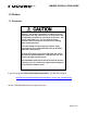
U.S.A. Do not open the enclosure unless totally familiar with electrical circuits. BBWX2 INSTALLATION GUIDE Observe the following compass safe distances to prevent interference to a magnetic compass: Only qualified personnel should work inside the equipment. BBWX2 Standard Compass 0.8m Steering Compass 0.5m Do not install the unit where it may get wet from rain or water splash. Water in the unit can result in fire, electrical shock or damage the equipment. Use only the specific power cable.
U.S.A. BBWX2 INSTALLATION GUIDE Table of Contents 1.0 Preface.......................................................................................................4 1.1 Disclaimer ................................................................................................4 2.0 Introduction...............................................................................................5 2.1 System Configuration .............................................................................5 2.
U.S.A. BBWX2 INSTALLATION GUIDE 1.0 Preface 1.1 Disclaimer Advisory – the weather information is subject to service interruptions and may contain errors or inaccuracies and consequently should not be relied upon exclusively. The service is provided as is. You are urged to check alternate weather information sources prior to making safety related decisions. You acknowledge and agree that you shall be solely responsible for use of the information and all decisions taken with respect thereto.
U.S.A. BBWX2 INSTALLATION GUIDE 2.0 Introduction The BBWX2 unit combines a Sirius Satellite Receiver (similar to the BBWX1) and an Ethernet 4-port Switch. The Receiver provides Sirius Satellite weather services and Sirius Radio (with two audio jacks). Currently, only Audio Port1 is active. Audio Port 2 is for future development. The Switch uses an Ethernet interface (100-BASE-TX or 10-BASE-T) to provide the network communications among the NavNet 3D equipment and PC.
BBWX2 INSTALLATION GUIDE U.S.A. 2.2 Receiver/Switch Specifications Sirius Weather Mariner or Voyager service levels Sirius Radio Dual Analog Output: 0 dBm into 600 Ω (0 dBv) Transmission speed Half-duplex/Full-duplex; 10 Mbps/100 Mbps I/O Ports 4 Ports (Shielded RJ45) Environmental Conditions Ambient Temperature -15 to 55 °C Relative Humidity 95%, 66°C, 18 hours EMC IEC 60945 Rev 4, Sections 9.2 & 9.3 Water Ingress IPX3 (IEC 60529) Power Supply 12 – 24 VDC, 0.
U.S.A. BBWX2 INSTALLATION GUIDE 3.0 BBWX2 Installation The BBWX2 does not come standard with a Sirius satellite antenna or antenna cable. These must be purchased separately. The BBWX2 is compatible with two Shakespeare antenna models: SRA-40 SRA 25 Furuno USA carries the following: WX1-005-003 WX1-005-004 Shakespeare SRA-40 antenna 25’ BBWX2 Antenna Cable For installations that require longer cable lengths you may contact your local Shakespeare outlet for options. 3.
U.S.A. BBWX2 INSTALLATION GUIDE 3.2 Mounting the Antenna • Do not install antenna where it can be damaged by being kicked or trampled. • The antenna beam is required to have an unrestricted view of the skies; this constitutes 5 ft [1.5 meters] out from the antenna and 1 ft [0.3 meter] above and below the antenna. • The antenna is to be installed on a flat horizontal surface. • The antenna can be installed as a standard “pedestal” mounting or “surface” mounting [non metallic surface only].
U.S.A. BBWX2 INSTALLATION GUIDE Note: For the power synchronization feature to function, 4 pair Ethernet cables must be used. See page 6 for a list of cable options. Connecting Cables to the BBWX2 Each cable type has a corresponding color-coded rubber cable grommet (for water resistance). The cable grommets are inserted into the enclosure cable tray of the Receiver unit (as shown below).
BBWX2 INSTALLATION GUIDE U.S.A. 3.4 Turning Power ON, LED function Power ON No operation is required for the user. Simply turn on the BBWX2’s DC power source to power it. Note: When the BBWX2 is used as a switch, make sure to power it before any other Network Devices (MFDs) BBWX2 LEDs The LEDs are displayed on the top surface of the unit as shown below. Satellite Receiver 10/100 4-Port Switch 100 Status 1 2 3 4 Link/Act U.S.A.
BBWX2 INSTALLATION GUIDE U.S.A. 4.0 Sirius Activation To enable the weather services and/or the radio services, you must first have a Sirius subscription to these services. Individual and combination weather and audio subscriptions are available. For more information, please visit www.sirius.com/marineweather or www.sirius.com/radio/packages.
U.S.A. BBWX2 INSTALLATION GUIDE 5.0 BBWX2 Operation 5.1 Connecting to and configuring the NavNet 3D MFD (display) 5.
BBWX2 INSTALLATION GUIDE U.S.A. 5.3 Power synchronization When connecting with PC(s), use shielded 2 pair Ethernet cable and set the applicable network port toggle switch(es) to OFF. When multiple MFD8/12/BBs are connected to the BBWX2 switch, using shielded 4 pair Ethernet cables, you can synchronize power to all of them by turning just one of them on. The port number of the toggle switch on the connector panel maps to a physical Network port as shown in the connector panel drawing below.
BBWX2 INSTALLATION GUIDE U.S.A. 5.
BBWX2 INSTALLATION GUIDE U.S.A. Switch LEDs - 100 Status Action GREEN – solid on 100 BASE-T None OFF 10 BASE-T None Status Action YELLOW – solid on Connected None YELLOW – blinking Data activity None Not connected None Switch LEDs – Link/Act OFF 5.5 General Maintenance Always turn your Receiver OFF before carrying out routine maintenance. Your Receiver is a sealed unit. DO NOT SEPARATE the unit. There are no serviceable parts or adjustments inside.