OPERATOR'S MANUAL SSB RADIOTELEPHONE Model FS-1575 FS-2575 FS-5075 www.furuno.
The paper used in this manual is elemental chlorine free. ・FURUNO Authorized Distributor/Dealer 9-52 Ashihara-cho, Nishinomiya, 662-8580, JAPAN All rights reserved. Printed in Japan A : JUL . 2011 C : AUG . 03, 2012 Pub. No.
IMPORTANT NOTICES General • This manual has been authored with simplified grammar, to meet the needs of international users. • The operator of this equipment must read and follow the descriptions in this manual. Wrong operation or maintenance can cancel the warranty or cause injury. • Do not copy any part of this manual without written permission from FURUNO. • If this manual is lost or worn, contact your dealer about replacement.
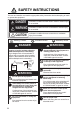
SAFETY INSTRUCTIONS The user and installer must read the appropriate safety instructions before attempting to install or operate the equipment. DANGER Indicates a condition that will result in death or serious injury if not avoided. WARNING Indicates a condition that can cause death or serious injury if not avoided. CAUTION Indicates a condition that can cause minor or moderate injury if not avoided.
SAFETY INSTRUCTIONS WARNING CAUTION Do not operate the [DISTRESS] key except in case of a life-endangering situation on your vessel. Operating the [DISTRESS] key transmits the distress alert. Accidental transmission may prevent search and rescue operations for actual emergency. If the distress alert is accidentally transmitted, contact the nearest station to cancel the alert.
DISTRESS ALERT How to send distress alert Below is the procedure for transmitting a distress alert via radiotelephone. Transmit the distress alert when a life-endangering situation occurs on your vessel. 1. Open the DISTRESS key cover then press the DISTRESS key for four seconds. The following screen appears. TX 2182 . 0 / RX 2182 . 00 kHz MSG TYPE NATURE LAT LON/UTC COMM MODE DSC FREQ : D I STRESS ALERT : UNDES I GNATED : 09 ° 12.1234’ N : 123 ° 45.
DISTRESS ALERT How to cancel distress alert You can cancel the distress alert while it is being sent or while waiting for its acknowledgement as follows. 1. Rotate the ENTER knob to select [CANCEL] in the user options area then push the knob. TX 8291 . 0 / RX 8291 . 00 kHz [ WAIT FOR ACK ] 09° 12.1234’ N/ 123° 45.1234’ E / 12 : 34 2, 4, 6, 8, 12, 16 MHz PRINT User options area CHANGE The following message appears on the screen. 2.
DISTRESS ALERT 4. Rotate the ENTER knob to select a frequency then push the knob. The following message appears on the screen. 5. Communicate with all ships via radiotelephone referring to the message at step 4. 6. Push the ENTER knob. The screen for the selection of frequency appears again. The frequency marked by asterisk shows that the call cancellation by voice was completed for that frequency. TX 2182 . 0 / RX 2182 . 00 kHz DISTRESS CANCEL MODE SELECT FREQUENCY AND *2 M - 2 1 8 2 . 0 k H z 4M-4125.
TABLE OF CONTENTS FOREWORD.................................................................................................................. xii SYSTEM CONFIGURATIONS...................................................................................... xiv 1. OPERATIONAL OVERVIEW .................................................................................1-1 1.1 1.2 1.3 1.4 1.5 1.6 1.7 1.8 1.9 1.10 1.11 2. Controls .....................................................................................
TABLE OF CONTENTS 4.3.1 How to send distress relay to coast station.................................................. 4-11 4.3.2 How to send distress relay to ships in your area.......................................... 4-12 4.4 How to Receive Distress Relay from Coast Station ................................................. 4-14 4.5 How to Cancel Distress Alert ................................................................................... 4-15 5. DSC GENERAL MESSAGE CALLING, RECEIVING.............
TABLE OF CONTENTS 6.16 6.17 6.18 6.19 6.20 6.21 7. 6.15.2 How to register addresses............................................................................6-13 6.15.3 How to edit addresses ..................................................................................6-14 6.15.4 How to delete addresses ..............................................................................6-15 6.15.5 How to create a DSC message with registered address ..............................
TABLE OF CONTENTS 9.3.2 How to save a file........................................................................................... 9-3 9.4 How to Edit Files ........................................................................................................ 9-3 9.4.1 How to cut and paste text............................................................................... 9-3 9.4.2 How to copy and paste text............................................................................ 9-4 9.4.
TABLE OF CONTENTS APPENDIX 5 PARTS LIST ..................................................................................... AP-23 APPENDIX 6 PARTS LOCATION ..........................................................................AP-26 SPECIFICATIONS ..................................................................................................... SP-1 INDEX .........................................................................................................................
FOREWORD A Word to the Owner of the FS-1575/2575/5075 Congratulations on your choice of the FURUNO FS-1575/2575/5075 SSB Radiotelephone. We are confident you will see why the FURUNO name has become synonymous with quality and reliability. Since 1948, FURUNO Electric Company has enjoyed an enviable reputation for innovative and dependable marine electronics equipment. This dedication to excellence is furthered by our extensive global network of agents and dealers.
FOREWORD • Log stores 50 each of latest general, distress and transmitted messages, in separate memory blocks. SSB • Receiving voice communication • Noise blanker function, Noise reduction function, Notch filter function, Squelch function are available.
SYSTEM CONFIGURATIONS *3 *3 For DSC routine frequency watch keeping receiver *1 PREAMP FAX-5 *1 *4 AUTOMATIC ANTENNA SWITCH AS-102 *4 RX antenna ANTENNA COUPLER AT-1575 (FS-1575) or AT-5075 (FS-2575, FS-5075) ANT. JUNC. BOX AJB1-1A or MATCHING BOX ARD-1 PREAMP FAX-5 BK INTERFACE BK-300 *1 2.
1. OPERATIONAL OVERVIEW 1.1 Controls SCAN 2182 RT/CH 1 2 NB 3 SQ 4 5 NR 6 7 8 NF 9 0 TUNE HANDSET VOLUME RF GAIN PUSH TO ATT Keep pressed for 4 sec in case of DISTRESS. The alert is transmitted with steady lighting.
1. OPERATIONAL OVERVIEW Control 2/NB key 3/SQ key 5/NR key 8/NF key 0/TUNE key key key ALARM lamp OVEN lamp 1.2 Function Turns the noise blanker on or off in the RT mode. Turns the squelch on or off in the RT mode. Reduces the noise in the RT mode (NR2 (High), NR1 (Low), Off). Turns the notch filter on or off in the RT mode. Tunes the antenna in radiotelephone operation. • Turns down the handset volume. • Moves the cursor when setting channel or RX frequency. • Turns up the handset volume.
1.
1. OPERATIONAL OVERVIEW 1.5 How to Adjust the Brilliance of the Display and Panel You can adjust the brilliance of the display and the panel as follows: 1. Press the BRILL key to show the [BRILL LEVEL SETUP] window. 2. Press the 1 key to switch the [DAY/NIGHT] mode. 3. To adjust the [DISPLAY] brilliance, rotate the ENTER knob or press the BRILL key. (Default setting: 17 for [DAY], 7 for [NIGHT]) 4. To adjust the [PANEL] brilliance, press the or (Default setting: 17 for [DAY], 12 for [NIGHT]) key. 5.
1. OPERATIONAL OVERVIEW 1. Press the SCAN key to show the DSC scan screen. Scanning starts. When receiving the appropriate frequency signal, the scanning stops, and the frequency is highlighted and flashes. 2. Press the SCAN key again to stop scanning the routine frequencies. Note: You can not stop the scanning manually for the distress alert. 3. Rotate the ENTER knob to move the cursor to the desired routine frequency which you want to watch. You can scan only the frequency selected by cursor. 4.
1. OPERATIONAL OVERVIEW 1.10 Intercom The built-in intercom permits voice communications between two control units. Calling You can call over the intercom in on or off hook condition. 1. Press the MENU key. 2. Rotate the ENTER knob to select [INTERCOM] then push the knob. The pop-up for calling appears and the called party's control unit rings. To cancel calling, press the CANCEL key. 3.
1. OPERATIONAL OVERVIEW How to finish a single session RT session 1. Press the TAB key to select the RT icon in the tab area. 2. Rotate the ENTER knob to select [QUIT] then push the knob. Step 2: Rotate the ENTER knob to select [QUIT]. Press the 6 key to open the position data window. Step 1: Press the TAB key to select the RT icon. DSC session The cursor is in the tab area when the DSC session starts. Rotate the ENTER knob to select [QUIT] then push the knob. TX 2177.0/ RX 2177.
1. OPERATIONAL OVERVIEW How to switch sessions When one session is active and another message arrives, a new session for the received message does not start automatically. Only one session can be active. For example, when you are transmitting a DSC message and another message arrives, the option [ACTIVE] appears to indicate the start of a new session. Press the TAB key to move the cursor to the tab area. TX 2182.0/ RX 2182.00 kHz [RT : SSB] CH : 200 TX : 2182.0 kHz RX : 2182.
1. OPERATIONAL OVERVIEW (Continued from previous page) TX 2177.0/ RX 2177.00 kHz NO ACTIVE [WAIT FOR ACK] INDIVIDUAL MSG ELAPSED TIME : 00H05M24S CAPTAIN_5075 TO : 987654321 COMM MODE : TELEPHONE COMM FREQ : TX 2170.0 / RX 2170.0 kHz ACTIVE INFO RT PRINT QUIT The icon disappears. How to close a session To manually close a session, select it with the TAB key. Rotate the ENTER knob to select [QUIT] in the user options area then push the knob. The session icon disappears from the tab area.
1. OPERATIONAL OVERVIEW This page is intentionally left blank.
2. SSB RADIOTELEPHONE You can do SSB communications from any screen which displays the communication frequency. 2.1 How to Select the Class of Emission You can select the class of emission from among the following: • [SSB]: Single Sideband • [TLX]: Telex • [AM]: AM (RX only) • [FAX]: FAX (RX only. Connect a FAX to this equipment to print FAX messages.) At the RT screen, select the class of emission as follows: 1.
2. SSB RADIOTELEPHONE Channel 1. Rotate the ENTER knob to select [CH] on the RT screen then push the knob. You can also show the channel setting window by pressing the RT/CH key. Channel setting window 2. A channel can be entered directly with the numeric keys, or by using the ENTER knob. See below for details. Enter channel with the numeric keys: Use the numeric keys to enter channel then push the ENTER knob.
2. SSB RADIOTELEPHONE 2.3 Transmission After selecting the class of emission and frequency, you can transmit by pressing the PTT switch on the handset. 2.3.1 Transmission procedure Maximum transmission power is achieved only when the antenna impedance and transmitter impedance match each other. Because the antenna impedance changes with frequency, antenna impedance matching with the transmitter impedance is done with the antenna coupler.
2. SSB RADIOTELEPHONE 2. Rotate the ENTER knob to select the option desired then push the knob. FS-1575/2575 [HIGH] FS-5075 No reducing [MID] 125 Wpep 350 Wpep [LOW] 90 Wpep - [LOW1] - 200 Wpep [LOW2] - 110 Wpep Note: The temperature of the power amplifier is monitored. When its temperature rises above a certain temperature, output power is automatically reduced. 2.3.
2. SSB RADIOTELEPHONE 2.4 Reception Check if the class of emission and receiving frequency are set properly. If necessary, set them again referring to sections 2.1 and 2.2. 2.4.1 RF gain (sensitivity) adjustment In normal use the sensitivity should be set for maximum. If the audio on the received channel is unclear or interfered with other signals, adjust (usually reduce) sensitivity to improve clarity. Rotate the RF GAIN/PUSH TO ATT knob to adjust gain (sensitivity).
2. SSB RADIOTELEPHONE (High) → [NR1] (Low) → Off). When the noise reduction function is active, is displayed on the RT screen. 2.4.6 or Notch filter The notch filter removes mixed CW (continuous wave) or beat signal interference. Press the 8/NF key on the RT screen to turn the notch filter on and off alternately. When the notch filter function is active, 2.4.7 is displayed on the RT screen. Squelch Squelch on/off The squelch mutes the audio output in the absence of an incoming signal.
3. DSC OVERVIEW 3.1 What is DSC? DSC is an acronym meaning Digital Selective Calling. It is a digital distress and general calling system in the MF and HF bands used by ships for transmitting distress alerts and general calls and by coast stations for transmitting the associated acknowledgements. For DSC distress, safety and urgency callings in the MF and HF bands, the frequencies are 2187.5, 4207.5, 6312.0, 8414.5, 12577.0, and 16804.5 kHz.
3. DSC OVERVIEW Contents of a DSC call • Calling category Call category Call DISTRESS DISTRESS ALERT, DISTRESS RELAY AREA, DISTRESS RELAY INDIVIDUAL GENERAL MEDICAL MSG, NEUTRAL MSG, INDIVIDUAL MSG, PSTN MSG, TEST MSG, GROUP MSG, AREA MSG, POSITION MSG, POLLING MSG • Station ID (MMSI) Your ship ID and sending station ID. Coast station ID begins with 00; Group ID begins with 0. • Priority Distress: Grave and imminent danger and request immediate assistance.
3. DSC OVERVIEW Alarm 3.
3. DSC OVERVIEW The marks "*", "-" appear on the DSC receiving screen in the following conditions: • "*" indicates a corrupt character in received data. • "-" indicates missing digits after decimal point when receiving position data with no info for expansion (expansion: digits after decimal point). Examples: 1) When receiving position data without expansion, the indication is "LAT: 12°34’N". 2) When receiving position data with expansion, the indication is "LAT: 12°34,5678’N".
4. DSC DISTRESS OPERATIONS Distress operation overview 1. Press the DISTRESS key. 2. Wait for the distress alert acknowledgement. 3. Communicate with the coast station. (1) (2) Ship in distress (Your ship) (3) Coast station (1) Ship in distress sends Distress Alert. (2) Coast station sends distress acknowledgement (DIST ACK). (3) Voice or telex communication between ship in distress and coast station. 4.
4. DSC DISTRESS OPERATIONS When the countdown shows 0S, the distress alert is sent. The audio alarm sounds for two seconds and the message "Sending DISTRESS ALERT." appears. The screen shows the contents of the distress alert call. The DISTRESS key lights in red and only the icon for DISTRESS transmission ( ) is displayed in the tab area. After the distress alert has been sent, the screen changes as below. Wait to receive the distress acknowledge call from a coast station.
4. DSC DISTRESS OPERATIONS 2. Press the CANCEL key to silence the audio alarm. Then, the LED stops flashing, and the pop-up message disappears. Count up the elapsed time after receiving distress acknowledge call. 09° 12.1234’ N/ 123° 45.1234’ E / 12 : 34 Icon for DISTRESS transmission 3. Communicate with the coast station via radiotelephone, following the instructions below.
4. DSC DISTRESS OPERATIONS 4. With [LAT] and [LON/UTC] selected, push the ENTER knob. [EPFS]: The position information from EPFS is automatically shown. [MANUAL]: Input your position manually. [NO INFO]: No information. 5. Rotate the ENTER knob to select [EPFS], [MANUAL] or [NO INFO] then push the knob. For [MANUAL], go to step 6. For others, go to step 7. 6. Use the numeric keys to enter latitude, longitude and UTC time.
4. DSC DISTRESS OPERATIONS 11. Press the DISTRESS key for four seconds to send the distress alert. The audio alarm sounds while pressing the key, and the key flashes in red. The countdown message appears on the screen while pressing the DISTRESS key (3S → 2S → 1S → 0S) (refer to the illustration at step 1 in paragraph 4.1.1). When the countdown shows 0S, the distress alert is sent. The audio alarm sounds for two seconds and the message "Sending DISTRESS ALERT." appears. 12.
4. DSC DISTRESS OPERATIONS 5. Type and transmit your message, giving the following information: • Ship's name and call sign • Nature of distress and assistance needed • Description of your ship 6. Press the function key F10 to disconnect the line. For NBDP details, see chapters 7 through 10. 4.2 How to Receive a Distress Alert When you receive a distress alert from a ship in distress, the audio alarm sounds and the LED flashes in red.
4. DSC DISTRESS OPERATIONS Action for ship receiving distress alert on MF band DSC distress alert received. Press the CANCEL key to silence alarm. Listen on 2182 kHz for 5 minutes. Did you receive acknowledge from CS and/or RCC? No Is distress traffic in progress? No Is the DSC distress call continuing? Yes Yes CS = Coast Station RCC = Rescue Coordination Center Is your ship able to aid ship in distress? No Yes Acknowledge the alert by Yes radiotelephone to the ship in distress on 2182 kHz.
4. DSC DISTRESS OPERATIONS 2. If you do not receive the distress acknowledge call from a coast station and you have received the distress alert more than twice, contact the ship in distress over radiotelephone. 3. Rotate the ENTER knob to select [ACK] in the user options area then push the knob. The following message appears on the screen. 4. Rotate the ENTER knob to select [Yes] then push the knob to transmit the distress acknowledge call to the ship in distress. The screen changes as below. 2187.
4. DSC DISTRESS OPERATIONS • Relay the distress alert in the following cases: • You have not received a distress acknowledge call from a coast station within five minutes after receiving a distress call. • You have not received a distress relay from other ship. • You cannot receive distress communications from other ship over radiotelephone.
4. DSC DISTRESS OPERATIONS Send the distress relay to coast station (on HF band) When you receive a distress alert from a ship in distress, the audio alarm sounds and the LED flashes in red. The icon for DISTRESS receiving ( and the pop-up message appears on the screen. ) appears in the tab area 1. Press the CANCEL key to silence the audio alarm and stop the flashing of the LED. 2. Rotate the ENTER knob to select [RELAY] in the user options area then push the knob.
4. DSC DISTRESS OPERATIONS When you receive the distress relay individual acknowledgement from the coast station, the audio alarm sounds and a pop-up message appears. Press the CANCEL key to silence the alarm and erase the pop-up message. Communicate with the coast station by telephone, over the frequency specified. If you do not receive the distress acknowledgement from a coast station, select [RELAY] then push the ENTER knob to transmit the distress relay again, over a different frequency. 4.
4. DSC DISTRESS OPERATIONS 8. Rotate the ENTER knob to select nature of distress then push the knob. 9. With [LAT] and [LON/UTC] selected, push the ENTER knob. 10. Rotate the ENTER knob to select [EPFS], [MANUAL] or [NO INFO] then push the knob. For [MANUAL], go to step 11. For others, go to step 12. 11. Use the numeric keys to enter latitude and longitude of the ship in distress.
4. DSC DISTRESS OPERATIONS 1. Press the DISTRESS MSG key and the OTHER DSC MSG key simultaneously to open the screen for composing the distress relay individual. 2. Rotate the ENTER knob to select [MSG TYPE] then push the knob. 3. Rotate the ENTER knob to select [RELAY AREA] then push the knob. The following message appears on the screen. 4. Rotate the ENTER knob to select [Yes] then push the knob. 5. With [AREA CR] selected, push the ENTER knob. 6.
4. DSC DISTRESS OPERATIONS 14. Rotate the ENTER knob to select [EPFS], [MANUAL] or [NO INFO] then push the knob. For [MANUAL], go to step 15. For others, go to step 16. 15. Use the numeric keys to enter latitude and longitude of the ship in distress. (If necessary, switch coordinates: 1 key to switch to North (East for longitude); 2 key to switch to South (West for longitude).) Push the ENTER knob. Also, enter the UTC time then push the ENTER knob. 16. With [COMM] selected, push the ENTER knob. 17.
4. DSC DISTRESS OPERATIONS 4.5 How to Cancel Distress Alert You can cancel the distress alert while it is being sent or while waiting for its acknowledgement as follows. 1. Rotate the ENTER knob to select [CANCEL] in the user options area then push the knob. The following message appears on the screen. 2. Rotate the ENTER knob to select [Yes] then push the knob to cancel the distress alert. The screen changes as below. TX 2187 . 5 / RX 2187 .
4. DSC DISTRESS OPERATIONS 4. Rotate the ENTER knob to select a frequency then push the knob. The following message appears on the screen. 5. Communicate with all ships via radiotelephone referring to the message at step 4. 6. Push the ENTER knob. The screen for the selection of frequency appears again. The frequency marked by asterisk shows that the call cancellation by voice was completed for that frequency. TX 2182 . 0 / RX 2182 . 00 kHz DISTRESS CANCEL MODE SELECT FREQUENCY AND *2 M - 2 1 8 2 .
5. DSC GENERAL MESSAGE CALLING, RECEIVING General procedure for non-distress DSC messages The procedure for sending and receiving non-distress DSC messages is similar among message types. The following is an example of the sequence for an individual call. 1. Send the individual message. 2. Wait for the individual message acknowledgement. 3. Start the communication.
5. DSC GENERAL MESSAGE CALLING, RECEIVING 2. Rotate the ENTER knob to select [MSG TYPE] then push the knob. 3. Rotate the ENTER knob to select [INDIVIDUAL MSG] then push the knob. 4. With [TO] selected, push the ENTER knob. 5. Rotate the ENTER knob to select [DIRECT INPUT] or [ADDRESS BOOK DATA] then push the knob. [ADDRESS BOOK DATA]: Select an MMSI from the [ADDRESS BOOK] (see section 6.15) then push the ENTER knob.
5. DSC GENERAL MESSAGE CALLING, RECEIVING 2) Rotate the ENTER knob to select DSC band then push the knob. One of the menus shown below appears depending on the band selected. 8MHz 18MHz 4MHz 12MHz 22MHz 6MHz 16MHz 25MHz 2MHz: To the ship station 2MHz: To the coast station 3) Rotate the ENTER knob to select DSC frequency then push the knob. The screen shows the DSC frequency band selected, at [DSC FREQ]. Urgency or safety priority 1) Rotate the ENTER knob to select [DSC FREQ] then push the knob.
5. DSC GENERAL MESSAGE CALLING, RECEIVING 13. Rotate the ENTER knob to select [GO TO CALL] then push the knob to send the individual call. The screen changes as below. 2177.0/ RX 2177.00 kHz [SENDING] ELAPSED TIME: INDIVIDUAL MSG 00H00M02S TO : 123456789 CAPTAIN_5075 COMM MODE : TELEPHONE COMM FREQ : TX 2170.0 /RX 2170.0 kHz INFO PRINT The timer starts counting up the time since the call was sent.
5. DSC GENERAL MESSAGE CALLING, RECEIVING Able acknowledge call received 1) Press the CANCEL key to silence the audio alarm and erase the pop-up message. 2) The working frequency is automatically set; you can communicate by radiotelephone or NBDP (see the following "How to send message by NBDP terminal unit"). 3) After you have completed communications, rotate the ENTER knob to select [QUIT] in the user options area then push the knob.
5. DSC GENERAL MESSAGE CALLING, RECEIVING Unable acknowledge call received 1) Press the CANCEL key to silence the audio alarm and erase the pop-up message. The reason for [UNABLE ACK] is displayed on the screen. TX 2177.0/ RX 2177.
5. DSC GENERAL MESSAGE CALLING, RECEIVING Send unable acknowledge automatically If the frequency or mode specified by the sending station is one that you cannot use, an unable acknowledge [CAN’T USE CH] is sent automatically. The [ACK SETTINGS] menu is set to [AUTO (UNABLE)]. It takes about seven seconds to transmit the call.
5. DSC GENERAL MESSAGE CALLING, RECEIVING 3. After you have completed communications, rotate the ENTER knob to select [QUIT] in the user options area then push the knob. TX 2170.0/ RX 2170.00 kHz [ACKNOWLEDGED] ELAPSED TIME: INDIV ABLE ACK 00H00M31S TO : 987654321 CAPTAIN_2575 COMM MODE : TELEPHONE COMM FREQ : TX 2170.0 /RX 2170.0 kHz INFO PRINT RESEND HOLD QUIT • How to send unable acknowledge call 1. Rotate the ENTER knob to select [UNABLE] in the user options area then push the knob. TX 2177.
5. DSC GENERAL MESSAGE CALLING, RECEIVING • How to send able acknowledge call and change frequency 1. Rotate the ENTER knob to select [PROPOSE] in the user options area then push the knob. TX 2177.0/ RX 2177.00 kHz COMPOSE MESSAGE MSG TYPE : INDIVIDUAL ACK TO : 987654321 CAPTAIN_2575 PRIORITY : ROUTINE COMM MODE : TELEPHONE COMM FREQ : 2170.0 kHz DSC FREQ : 2177.0 kHz GO TO CALL 2. Rotate the ENTER knob to select [COMM MODE] then push the knob. 3.
5. DSC GENERAL MESSAGE CALLING, RECEIVING 5.2 Group Call A group call is for calling a specific group by specifying its group MMSI. 5.2.1 How to send a group call 1. Press the OTHER DSC MSG key. 2. Rotate the ENTER knob to select [MSG TYPE] then push the knob. 3. Rotate the ENTER knob to select [GROUP MSG] then push the knob. 4. With [TO] selected, push the ENTER knob. 5. Rotate the ENTER knob to select [DIRECT INPUT] or [ADDRESS BOOK DATA] then push the knob.
5. DSC GENERAL MESSAGE CALLING, RECEIVING 12. Referring to "How to set working channel, frequency" on page 5-3, set the frequency or channel. 13. Rotate the ENTER knob to select [GO TO CALL] then push the knob to send the group call. The screen changes as below. 2170.0/ RX 2170.00 kHz 2177.0/ RX 2177.00 kHz [SENDING] ELAPSED TIME: GROUP MSG 00H00M04S TO : 012345678 COMM MODE : TELEPHONE COMM FREQ : TX 2170.0 /RX 2170.
5. DSC GENERAL MESSAGE CALLING, RECEIVING 5.3 Geographical Area Call The purpose of a geographical area call is to send a call to all ships within the area you designate. In the figure below, for example, the call is sent to all ships within 2434°N, 135-140°W (QUADRANT) and 34°N, 140°W, range: 500 NM (CIRCLE). Reference point (For example, 34°N, 140°W) 34°N 500 NM 10° Reference point (For example, 34°N, 140°W) 24°N 5° 140°W 135°W QUADRANT 5.3.1 CIRCLE How to send a geographical area call 1.
5. DSC GENERAL MESSAGE CALLING, RECEIVING [CIRCLE]: Using the numeric keys, enter latitude and longitude of reference point and radius of area. To change coordinate, select it and press the 1 key for North or East; 2 key for South or West. After entering data, push the ENTER knob. [QUADRANT]: Using the numeric keys, enter latitude and longitude of reference point and southerly degrees and easterly degrees of area.
5. DSC GENERAL MESSAGE CALLING, RECEIVING 5.3.2 How to receive a geographical area call When you receive a geographical area message, the audio alarm sounds. The icon ( ) appears in the tab area, and the pop-up message "SAFETY (URGENCY) AREA message received! [CANCEL]: Stop alarm" appears. TX 2182.0/ RX 2182.00 kHz [ACKNOWLEDGED] ELAPSED TIME: AREA MSG 00H00M31S TO : 987654321 CAPTAIN_2575 COMM MODE : TELEPHONE COMM FREQ : TX 2170.0 /RX 2170.0 kHz INFO PRINT HOLD QUIT 1.
5. DSC GENERAL MESSAGE CALLING, RECEIVING 3. Rotate the ENTER knob to select [SPECIAL MSG] then push the knob. 4. Rotate the ENTER knob to select [NEUTRAL MSG] then push the knob. [PRIORITY] is automatically selected to [URGENCY]. 5. With [AREA CR] selected, push the ENTER knob. 6. Enter the area range referring to step 5 in paragraph 5.3.1. 7. With [COMM MODE] selected, push the ENTER knob. 8. Rotate the ENTER knob to select [TELEPHONE] or [NBDP-FEC] then push the knob. 9.
5. DSC GENERAL MESSAGE CALLING, RECEIVING 15. Inform all ships by radiotelephone that your ship is not a participant in armed conflict. For communication by NBDP, see "How to send message by NBDP terminal unit" on page 5-5. 16. After you have completed communications, rotate the ENTER knob to select [QUIT] in the user options area then push the knob. 5.4.2 How to receive a neutral craft call When you receive a neutral craft call, the audio alarm sounds.
5. DSC GENERAL MESSAGE CALLING, RECEIVING 5.5 Medical Transport Call The medical transport call informs all ships, by urgency priority, that your ship carries medical supplies. The medical transport call must be enabled on the [SPECIAL MSG] menu. See section 6.18. 5.5.1 How to send a medical transport call 1. Press the OTHER DSC MSG key. 2. Rotate the ENTER knob to select [MSG TYPE] then push the knob. 3. Rotate the ENTER knob to select [SPECIAL MSG] then push the knob. 4.
5. DSC GENERAL MESSAGE CALLING, RECEIVING 14. Rotate the ENTER knob to select [GO TO CALL] then push the knob to send the medical transport call. 2187.5/ RX 2187.50 kHz [SENDING] ELAPSED TIME: MEDICAL MSG 00H00M04S AREA : 34 ° 00 ’ N / 135 ° 00 ’ E 0500NM COMM MODE : TELEPHONE COMM FREQ : TX 2182.0 /RX 2182.0 kHz INFO PRINT 15. Inform all ships by radiotelephone that your ship is transporting medical supplies. For communication by NBDP, see "How to send message by NBDP terminal unit" on page 5-5. 16.
5. DSC GENERAL MESSAGE CALLING, RECEIVING 3. Watch on the working frequency. Communicate by radiotelephone or NBDP (see the following "Medical transport call received by NBDP terminal unit"). 4. After you have completed communications, rotate the ENTER knob to select [QUIT] in the user options area then push the knob. Medical transport call received by NBDP terminal unit After receiving a medical transport call, confirm the following. • The control unit's screen shows the TX and RX frequencies.
5. DSC GENERAL MESSAGE CALLING, RECEIVING 5.7 Position Call There are two types of position calls: your ship requests position of another ship and other station requires your ship's position. Find position of other station (1) Position request call (2) Position Information Your Station Other Station Send your ship's position to other station (1) Request ship's position (2) Send position Information Other Station Your Station 5.7.1 How to request other ship's position 1. Press the OTHER DSC MSG key.
5. DSC GENERAL MESSAGE CALLING, RECEIVING 5. Rotate the ENTER knob to select [DIRECT INPUT] or [ADDRESS BOOK DATA] then push the knob. [ADDRESS BOOK DATA]: Select an MMSI from the [ADDRESS BOOK] (see section 6.15) then push the ENTER knob. [DIRECT INPUT]: Enter MMSI of station, which you want to know its position, with the numeric keys then push the ENTER knob. 6. With [DSC FREQ] selected, push the ENTER knob. 7. Rotate the ENTER knob to select DSC frequency desired then push the knob. 8.
5. DSC GENERAL MESSAGE CALLING, RECEIVING 9. Press the CANCEL key to silence the audio alarm and erase the pop-up message. There are two types of ACK screens; one with position information and one with no position information. 2187.5/ RX 2187.50 kHz 2187.5/ RX 2187.50 kHz [ACKNOWLEDGED] ELAPSED TIME: POSITION ACK 00H01M16S FROM : 123456789 CAPTAIN_5075 LAT : 34°42.2800’N LON/UTC : 135°19.
5. DSC GENERAL MESSAGE CALLING, RECEIVING • Send the ACK with position information: With [ACCEPT] selected, push the ENTER knob. 2187.5/ RX 2187.50 kHz [SENDING] ELAPSED TIME: POSITION ACK 00H01M16S TO : 987654321 CAPTAIN_2075 POS/UTC : 09 ° 12 ’ N 123 ° 45 ’ E / 12 : 34 INFO PRINT • To send the ACK with no position information: Rotate the ENTER knob to select [UNABLE] in the user options area then push the knob. The screen changes as below. 2187.5/ RX 2187.
5. DSC GENERAL MESSAGE CALLING, RECEIVING 3. Rotate the ENTER knob to select [PSTN MSG] then push the knob. 4. With [TO] selected, push the ENTER knob. 5. Rotate the ENTER knob to select [DIRECT INPUT] or [ADDRESS BOOK DATA] then push the knob. [ADDRESS BOOK DATA]: Select an MMSI from the [ADDRESS BOOK] (see section 6.13) then push the ENTER knob. [DIRECT INPUT]: Enter MMSI of coast station (seven digits) with the numeric keys then push the ENTER knob. 6. Rotate the ENTER knob to select [TEL NO.
5. DSC GENERAL MESSAGE CALLING, RECEIVING with the party you called. The elapsed time since starting communication is displayed. Note: When you receive this ABLE ACK on the working frequcency in on hook condition, END OF CALL is sent automatically. The communication is disconnected. 2. To quit the communications, do one of the following. • On hook the handset or press the CANCEL key. END OF CALL is sent automatically. The waiting ACK for END OF CALL screen appears.
5. DSC GENERAL MESSAGE CALLING, RECEIVING Unable acknowledgement The automatic unable acknowledge is sent. The audio alarm sounds and the LED flashes in green. Press the CANCEL key.
6. MENU OPERATION The menu can be accessed from both the RT and DSC screens. Note: The menu can not be opened when awaiting acknowledgement of a distress alert. 6.1 How to Open/Close the MENU Screen 1. Press the MENU key to open the [MENU] screen. These marks indicate additional menus. 2. Rotate the ENTER knob to select the desired menu item then push the knob. You can also select the desired menu item by pressing the 1 to 9 keys. The menu items that have a X indicate additional menus.
6. MENU OPERATION 6.2 User Channels The [USER CH] menu allows registration and deleting of user TX and RX channels, which are available where permitted by the Authorities. A maximum of 256 channels can be registered. A user channel consists of four or five digits. The setting range is 01 to 029 for band, 00 to 99 for band channel. 01234 Band Band channel NOTICE FURUNO will assume no responsibility for the disturbance caused by the unlawful or improper setting of user channels. 6.2.
6. MENU OPERATION 2. With [MODE] selected, push the ENTER knob. 3. Rotate the ENTER knob to select the mode desired then push the knob. 4. With [CH] selected, push the ENTER knob. 5. Enter band and band channel with the numeric keys. 6. With [TX FREQ] selected, push the ENTER knob. 7. Enter TX frequency with the numeric keys. 8. With [RX FREQ] selected, push the ENTER knob. 9. Enter RX frequency with the numeric keys. 10. With [REGISTER] selected, push the ENTER knob. 6.2.3 How to edit user channels 1.
6. MENU OPERATION 6.2.4 How to delete user channels Open the [USER CH] list then follow the applicable procedure below. Individual user channel 1. Rotate the ENTER knob to select the user channel to delete then press the 4 key. 2. With [DELETE SELECTION] selected, push the ENTER knob. 3. Rotate the ENTER knob to select [Yes] then push the knob. User channels by mode 1. Press the 6 key several times to select the desired mode. 2. Press the 4 key. 3.
6. MENU OPERATION 6.2.6 How to select user channels for SSB mode Rotate the ENTER knob to select the user channel desired on the [USER CH] list then press the 8 key. The RT screen for the selected user channel appears. Press the 8 key. 6.3 Log File Three log file modes are provided for storage of calls: • [RX GENERAL] (received ordinary log) • [RX DISTRESS] (received distress log) • [TX] (transmitted log) Each mode stores 50 calls. The latest call is saved as log no.1 and the log no.
6. MENU OPERATION 3. When there are multiple pages, press the 1 key for the previous page and the 3 key for the next page. Rotate the ENTER knob to select a desired log then push the knob. The contents of the selected log file are displayed as below. To return to the [MENU] screen, press the CANCEL key. RX GENERAL INDIVIDUAL PRIORITY FROM TO COMM MODE COMM OPTION COMM FREQ LOG NO. 1 10/APRL/2012 19:17 : SAFETY : 123456789 : 987654321 : TELEPHONE : NO INFO : TX 16420.0kHz/RX 16420.
6. MENU OPERATION 6.4 Squelch Frequency The squelch frequency (ex. for high voice) can be changed as follows (default setting: 1000 Hz): 1. Rotate the ENTER knob to select [SYSTEM] on the [MENU] screen then push the knob. 2. With [SQ FREQ] selected, push the ENTER knob. 3. Rotate the ENTER knob to adjust frequency (setting range: 500-2000 Hz) then push the knob. 6.5 Key Assignment You can program the 1, 4 and 7 keys to provide one-touch access to a required function.
6. MENU OPERATION 3. Rotate the ENTER knob to select [F1], [F2] or [F3] then push the knob. 4. Rotate the ENTER knob to select the function desired then push the knob. 6.6 How to Print Messages The [PRINT] menu enables/disables automatic printing of all transmitted and received calls and the results of the daily test. 1. Rotate the ENTER knob to select [SYSTEM] on the [MENU] screen then push the knob. 2. Rotate the ENTER knob to select [PRINT] then push the knob. 3.
6. MENU OPERATION 5. For manual input, use the numeric keys to enter latitude/longitude of your position, and UTC. To change coordinate, select it and press the 1 key for North or East; the 2 key for South or West. After entering each data, push the ENTER knob. Setting window for latitude Enter latitude. Push the ENTER knob. Setting window for longitude Enter longitude. Push the ENTER knob. Setting window for UTC Enter UTC then push the ENTER knob.
6. MENU OPERATION 6.9 Timeout Setting The menu screen and/or the inactive sessions (icons) can be closed automatically when there is no menu operation for a specific time. You can set the time interval for auto closing of the menu and inactive session. 1. Rotate the ENTER knob to select [SYSTEM] on the [MENU] screen then push the knob. 2. Rotate the ENTER knob to select [TIMEOUT] then push the knob. *: [FAX] is unavailable. 3. Rotate the ENTER knob to select the item desired then push the knob. 4.
6. MENU OPERATION 4. Rotate the ENTER knob to select [ENABLE] or [DISABLE] then push the knob. For [ENABLE], "FAX" is added to the class of emission selection menu. Class of emission 6.11 How to Select the Antenna Select the antenna to use for TX and RX, common or separate. 1. Rotate the ENTER knob to select [SYSTEM] on the [MENU] screen then push the knob. 2. Rotate the ENTER knob to select [RX SETUP] then push the knob. 3. Rotate the ENTER knob to select [ANT SELECT] then push the knob. 4.
6. MENU OPERATION 1) Rotate the ENTER knob to select [+0.00 kHz] then push the knob. 2) Rotate the ENTER knob to adjust the receiving frequency (setting value: -0.20 to +0.20). 6.13 External Alarm Setting The [EXTERNAL ALARM] menu enables/disables output of the contact signal for urgency, safety and routine frequencies to an external alarm system. 1. Rotate the ENTER knob to select [SYSTEM] on the [MENU] screen then push the knob. 2. Rotate the ENTER knob to select [EXTERNAL ALARM] then push the knob.
6. MENU OPERATION 6.15 Address Book You can register a maximum of 50 MMSI or the address name (max. 20 letters) in the memory. 6.15.1 List for address data 1. Rotate the ENTER knob to select [DSC] on the [MENU] screen then push the knob. 2. Rotate the ENTER knob to select [ADDRESSBOOK] then push the knob. When 50 addresses are registered, this is not available. Key/knob ENTER CANCEL 6.15.2 Function • Move the cursor by rotating the ENTER knob.
6. MENU OPERATION 3. With [NAME] selected, push the ENTER knob. 4. Enter the address name (max. 20 letters) with the numeric keys then push the ENTER knob. 5. With [MMSI] selected, push the ENTER knob. 6. Enter the MMSI with the numeric keys then push the ENTER knob. 7. With [REGISTER] selected, push the ENTER knob. 6.15.3 How to edit addresses 1. Open the [ADDRESS BOOK] screen. 2. Rotate the ENTER knob to select the address to edit then push the knob. : 24 : 20 :6 LIST Push the ENTER knob. 3.
6. MENU OPERATION 6.15.4 How to delete addresses Open the [ADDRESS BOOK] screen then follow the applicable procedure below. Individual address 1. Rotate the ENTER knob to select the address to delete then press the 4 key. 2. With [DELETE SELECTION] selected, push the ENTER knob. 3. Rotate the ENTER knob to select [Yes] then push the knob. Address by type 1. Press the 6 key several times to select desired type. 2. Press the 4 key. 3. Rotate the ENTER knob to select [DELETE LIST] then push the knob. 4.
6. MENU OPERATION 6.16 TX Message Preparation For the individual, PSTN, group and test messages, you can create messages and store them in the memory for future use. You can edit, send or delete these messages. A maximum of 100 messages can be stored into the memory. 6.16.1 List for message files 1. Rotate the ENTER knob to select [DSC] on the [MENU] screen then push the knob. 2. Rotate the ENTER knob to select [MSG FILE] then push the knob.
6. MENU OPERATION • 3 key: Go to the detailed information screen for the next message file. • 4 key: Delete the selected message file. The following message appears on the screen. Rotate the ENTER knob to select [Yes] then push the knob. 6.16.2 Individual calls 1. Open the [MESSAGE FILE] list. 2. Press the 5 key to open the [MESSAGE FILE ENTRY] screen. 3. With [MSG TYPE] selected, push the ENTER knob. 4. Rotate the ENTER knob to select [INDIVIDUAL MSG] then push the knob. 5.
6. MENU OPERATION 13. Rotate the ENTER knob to select [FILE NAME] then push the ENTER knob. 14. Enter the file name (max. 20 letters) with the numeric keys. 15. With [REGISTER] selected, push the ENTER knob. 6.16.3 Group calls 1. Open the [MESSAGE FILE] list. 2. Press the 5 key to open the [MESSAGE FILE ENTRY] screen. 3. With [MSG TYPE] selected, push the ENTER knob. 4. Rotate the ENTER knob to select [GROUP MSG] then push the knob. 5. With [TO] selected, push the ENTER knob. 6.
6. MENU OPERATION 6. Rotate the ENTER knob to select [DIRECT INPUT] or [ADDRESS BOOK DATA] then push the knob. [ADDRESS BOOK DATA]: Select an MMSI from the [ADDRESS BOOK] (see section 6.15) then push the ENTER knob. [DIRECT INPUT]: Enter MMSI of coast station (seven digits) with the numeric keys then push the ENTER knob. 7. With [TEL] selected, push the ENTER knob. 8. Enter the telephone no. (up to 16 digits) with the numeric keys then push the ENTER knob. 9. With [DSC FREQ] selected, push the ENTER knob.
6. MENU OPERATION 3. Push the ENTER knob to open [MESSAGE FILE EDIT] screen. 4. Rotate the ENTER knob to select the item to edit then push the knob. 5. Change the setting accordingly. 6. Rotate the ENTER knob to select [REGISTER] then push the knob. 7. Rotate the ENTER knob to select [Yes] then push the knob. 6.16.7 How to send prepared messages How to send without modification 1. Open the [MESSAGE FILE] list. 2. Rotate the ENTER knob to select the message file desired then press the OTHER DSC MSG key.
6. MENU OPERATION Prepared messages by type 1. Press the 6 key several times to select the desired type. 2. Press the 4 key. 3. Rotate the ENTER knob to select [DELETE LIST] then push the knob. 4. Rotate the ENTER knob to select [Yes] then push the knob. All prepared messages 1. Press the 4 key. 2. Rotate the ENTER knob to select [DELETE ALL LISTS] then push the knob. 3. Rotate the ENTER knob to select [Yes] then push the knob. 6.
6. MENU OPERATION 6.18 Special Messages Permission to transmit NEUTRAL CRAFT and MEDICAL TRANSPORT is enabled or disabled as follows: 1. Rotate the ENTER knob to select [DSC] on the [MENU] screen then push the knob. 2. Rotate the ENTER knob to select [SPECIAL MSG] then push the knob. 3. Rotate the ENTER knob to select [NEUTRAL] or [MEDICAL] then push the knob. 4. Rotate the ENTER knob to select [ABLE] or [UNABLE] then push the knob. 6.
6. MENU OPERATION Note: Distress frequencies can be stored on the routine frequency memory. This is convenient for backing up the watch-keeping receiver. Distress, urgency and safety frequencies 1. Rotate the ENTER knob to select [DSC] on the [MENU] screen then push the knob. 2. Rotate the ENTER knob to select [DISTRESS SCAN] then push the knob. 3. Rotate the ENTER knob to select frequency band then push the knob. 4. Rotate the ENTER knob to select [ON] or [OFF] as appropriate then push the knob.
6. MENU OPERATION Default: [2] Turn beep on (setting: [1] - [3]) or off (setting: [0]) when a key is pressed. Default: [MUTE] Turn the speaker on or off when the handset is off hook. Rotate the ENTER knob to set volume then push the knob. Default: [500NM] Turn sound alarm on or off for the distress alarm received from a ship in distress which is more than 500 NM from your ship. 6.21 Alarm Lists The [ALARM] menu shows all currently violated alarms.
7. NBDP SYSTEM OVERVIEW 7.1 How to Turn on the NBDP System Turn on the terminal unit and the printer with their respective power switches. TERMINAL UNIT IB-583 TERMINAL UNIT IB-585 The power switch backlights for IB-583 and IB-585 light in green during power-on. Floppy disk drive Power switch PRINTER PP-510 Power switch SD card drive USB connector (Connect the keyboard here.) Power switch Note 1: To power on the system, turn on the control unit then turn on the NBDP terminal unit.
7. NBDP SYSTEM OVERVIEW “2012-04-10” for IB-583 “ARQ Error” for IB-583 1:File 2:Edit 3:Operate 4:Window 5:Station 6:System 7:WRU 8:HR 9:Over 10:Break 10-Apr-2012 15:10:30 UTC Caps Eng Station Name : Frequency (T/R) : . / . (kHz) Comm Mode : AUTO Comm Status : Connect Send Lock Error Sending Volume : (%) Error : 0 ARQ Time : 0(sec) Here is the message area. The cursor at the left bottom of the screen flashes during operation. Date and time: day-month-year, hour: min: sec (see page 7-8.
7. NBDP SYSTEM OVERVIEW Note 1: To switch between Russian and English input, press the Alt key while holding down the Shift key. (This is available in Russian mode only.) "Eng" or "Rus" appears on the top right of the screen. This shift status is not stored. When you turn on the power next time, you reset the shift status as necessary. Note 2: The comma and period can not be entered in the “Russian-shift” status. To enter these characters, switch to the “English-shift” status.
7. NBDP SYSTEM OVERVIEW Note 3: The carriage-return and line-feed codes "CR LF" are automatically sent with pressing the Enter key during NBDP communication. Press the ← or ↓ key if you want to send only "CR" or "LF". Note 4: "Letter Shift" and "Figure Shift" are automatically inserted if necessary.
7. NBDP SYSTEM OVERVIEW 7.4 Function Keys, Menu Operation The function keys at the top of the keyboard control most of operations through a menu system. Most of the screenshots on this manual are for IB-585. 7.4.1 Menu conventions Reverse highlighting The cursor-selected menu item is displayed with white characters on a black background. Underline The underline shows the currently selected option. In the figure below, for example, [ARQ], [Channel] and [ON] are underlined.
7. NBDP SYSTEM OVERVIEW 7.4.3 Function key description Function key F1: [File] menu The [File] menu is where you create, open, save and print telex messages. Floppy disks or SD cards are also formatted by this menu. File 1: New 2: Open 3: Close 1: Open a new untitled window. 2: Open files saved on floppy disks or SD cards. 3: Close files with saving or discarding. 4: Delete 4: Delete files on floppy disks or SD cards. 5: Rename 5: Rename files on floppy disks or SD cards.
7. NBDP SYSTEM OVERVIEW Function key F3: [Operate] menu The [Operate] menu mainly controls transmission and reception. Operate 1: Select a station on the station list. 2: Start macro operation. For details, see section 10.10. 3: Select a file then transmit it. 4: Stop sending a file. 5: Start/stop frequency scanning. 6: Select communication mode for reception; AUTO, ARQ, FEC. Note: Do not select DIRC (only for IB-583). 7: Enable timer programming.
7. NBDP SYSTEM OVERVIEW Function key F5: [Station] menu The [Station] menu provides for storage of stations, timer program setup, user channel setup, and entry of various ID codes. Station 1: Register stations. 1: Station Entry 2: Register timer programs. 2: Timer Operation Entry 3: Scan Entry 3: Register scan groups for scanning. 4: User Channel Entry* 4: Register user channels. 5: Register own ship's answerback code. 6: Register own ship's group ID code (4 or 5 digits).
7. NBDP SYSTEM OVERVIEW Menu item Function [Setup] Lock, change settings, restore default system settings. [Slave Delay] Set the length of the slave delay timing from the end of RX to the start of TX in the ARQ mode. The default setting is suitable in most cases. This item cannot be adjusted by the user. 3 char. RX 3 char.
7. NBDP SYSTEM OVERVIEW Function key F10: Break During communication: Disconnect the line. During reception mode: Goes to the standby mode. Note: For NBDP activated by the DSC function, select [QUIT] option on the control panel to cancel reception mode and go to the standby mode.
8. NBDP PREPARATIONS This chapter provides the procedures necessary for preparing the NBDP terminal unit. For automatic telex, you need to register the following: • Your ship's ID and answerback codes mandatory • Stations • Timer programs • Scan channel groups • User channels 8.1 Registration of Answerback & ID Codes Enter your ship's answerback and ID codes as shown below. Note: The answerback and ID codes cannot be changed once entered; be sure to correctly enter the codes. 8.1.
8. NBDP PREPARATIONS 8.1.2 How to register ID codes 1. Press the function key F5 then the 5, 6, 7 or 8 key for IB-585 to enter the Group ID Code (4 or 5 digits), Group ID Code (9 digits), Select ID Code (4 or 5 digits) or Select ID Code (9 digits), respectively. (For IB-583, press the function key F5 then the 6, 7, 8 or 9 key.) Select ID Entry Select ID Code (4/5) _ 2. Enter Group ID or Select ID then press the Enter key. A prompt asks for confirmation of the data. 3.
8. NBDP PREPARATIONS 3. With [Channel] selected, enter a channel number. Note 1: 100 channels can be registered. When you attempt to register more, the message "Channel memory is full. Press any key to escape." appears. In this case delete unnecessary channels to register new ones. Note 2: If the channel entered already exists, the message "Channel by that number already exists. Press any key to escape." appears. Press any key then enter another number. 4. Press the ↓ key to select [Tx Freq].
8. NBDP PREPARATIONS 2. If [Create] is not underlined, press the →, ↑ and Enter keys to underline it. 3. With [Station] selected, enter station name using up to 18 characters. 4. Press the ↓ key to select [ID Code]. Enter station ID code. 5. Press the ↓ key to select [Mode]. Select either communication mode with the ← or → keys. [ARQ]: Automatic Retransmission Request [FEC]: Forward Error Correction 6. Press the ↓ key to select [CH/Table]. Select [Channel] or [ScanTable]. 7.
8. NBDP PREPARATIONS 8.3.2 How to edit/delete stations 1. Press the function key F5 then the 1 key to open the [Station Entry] screen. 2. Press the ↓ key to select a station name from the [Station List]. 3. Press the → key then the ↓ key to select [Change] and press the Enter key. 4. Do one of the following; Edit station: Use the ↑, ↓ and the Backspace keys to make corrections. Delete station: Erase station name with the Backspace key. 5. Press the Enter key twice. 6. Press the Esc key. 8.
8. NBDP PREPARATIONS 8. Press the ↓ key to select [Stop Time]. Enter stop time, in 24-hour notation. 9. Press the ↓ key to select [Receive/Send]. Select operation category; [Receive] or [Send]. If you select [Send], go to step 10. For [Receive], go to step 12. 10. For [Send], insert the floppy disk or the SD card to the drive then press the ↓ key to select [File to Send]. 11. Press the → key to open the TX window, select a file, then press the Enter key twice. 12. Press the Enter key.
8. NBDP PREPARATIONS 8.5.1 How to register scan channel groups You can register ITU and user scan channels as follows: 1. Press the function key F5 then the 3 key to open the [Scan Entry] screen. Scanning Group List Scan Entry Create Change Group Name Ch Dwell Time Receiving Mode*1 Auto Search No. 0*2 1 2 3 4 5 6 Channel Scanning Set Up : : 4.5 sec (2.7-4.5 sec) : AUTO ARQ FEC : OFF ON Rx Freq Tx Freq Press the key to scroll the screen.
8. NBDP PREPARATIONS 8. Enter the channel number (ITU or user channels) then press the → key to select [Scan]. Note: If you enter an invalid channel, the message "Channel by that number does not exist. Press any key to escape." appears. Press any key then enter a valid channel. 9. Press the ↓ key to select line No. 2. Enter a channel number. 10. Enter other channel numbers then press the Enter key. A confirmation message appears. 11. Press the Enter key again to save the data.
8. NBDP PREPARATIONS 3. Press the ↓ key to select [Window Color] then press the Enter key. 4. With [Window Color Setup] selected, press the Enter key. 5. Press the ← or → key to select the item to change: [BASE WINDOW], [BACK SCROLL], [EDIT 1-2], [FUNCTION], [SUB MENU 1-3], [MESSAGE]. Window Color Change Window Color Setup Default Color To Change: ENTER To quit: ESC Window Color Setup Window Fore Color Back Color : [BASE WINDOW : [L-WHITE : [BLUE ] ] ] To Change: ENTER To Change Value: L<=>R 6.
8. NBDP PREPARATIONS Default for each preset Preset1 (original) Brightness Base window Back scroll Edit1 Edit2 Function Sub menu1 Sub menu2 Sub menu3 Message 8.
9. NBDP FILE OPERATIONS This chapter mainly describes how to create, save, open, edit and print files. The [Edit] menu provides a full lineup of editing facilities, including search and replace. 9.1 How to Open and Close Files To create a telex message, you need to make a new file with the File Open command. When you open a new file, it is placed (opened) in one of two working areas. When both working areas are occupied, you must close a file to open a new file. This is done with the File Close command.
9. NBDP FILE OPERATIONS 2. Press the 1 key to select [New]. The title bar shows [UNTITLED 1] or [UNTITLED 2]. The cursor marks the location where you can type text. 3. Type your message. Note: Lower case letters are sent as upper case letters. Also, do not use the symbols #, &, *, $ and % in telex messages. Do not put "$$$" in the middle of a TX message, but at the end. The communication line is automatically disconnected when this string is detected.
9. NBDP FILE OPERATIONS 9.3.1 How to format floppy disks or SD cards Before you save a file to a floppy disk or an SD card, the disk or the card must be formatted. Format the disk or the card as below. 1. Press the function key F1 to open the [File] menu. 2. Insert a new floppy disk or SD card in the drive. 3. Press the 0 key to select [Floppy Disk Format] or [SD Card Format]. 4. Press the ↑ key to select [Yes] then press the Enter key. The screen shows formatting progress as below.
9. NBDP FILE OPERATIONS How to cut text 1. Place the cursor on the first character of the text to cut. 2. Highlight the text to cut by pressing and holding the Shift key while pressing the → key. If you highlighted the text which you do not want to cut by mistake, press the ← key to adjust the highlight. <[1]UNTITLED1> CONGULATULATION ON YOUR CHOICE OF DP-6 INMARSAT B MOBILE EARTH STATION. WE ARE CONFIDENT THAT YOU WILL ENJOY MANY YEARS OF OPERATION WITH THIS FINE PIECE OF EQUIPMENT The highlight 3.
9. NBDP FILE OPERATIONS 5. Place the cursor at the exact spot in the message where the text now in the paste buffer memory is to start then press the Ins or Insert key. Working Area 1 1 Open file 3 Open file Floppy Disk or SD card 2 Transfer (copy) Paste Buffer Memory Working Area 2 4 Paste (Combine) Copy and paste flow diagram 9.4.4 How to search text The [Search] feature lets you search for text in a forward or backward direction. 1.
9. NBDP FILE OPERATIONS 3. Press the ↓ key to select [Replace with] then type a new word. 4. Press the → key. 5. Press the ↑ or ↓ key to select [Forward] or [Backward] to search the file in a forward or backward direction respectively from the cursor position. 6. Press the → key. 7. Press the ↑ or ↓ key to select whether you want to be queried or not each time the word is found. [Query]: Stop at each occurrence of the word to answer yes or no for replacement.
9. NBDP FILE OPERATIONS 3. Press the 2 key. A list of files on the floppy disk or the SD card appears. Open Text Load/Merge(TAB:Change) [A:\TEST1. ] File name Size Date & Time LOG File 52 12-04-10 17:25 TEST1. 120 12-04-10 16:30 TEST2. 151 12-04-10 9:25 TEST3. 180 12-04-10 20:16 NBDP 169 12-04-10 6:23 [ End of Directory 4 Files exist To select : ENTER ] 1454000 bytes free To view : SPACE To quit : ESC 4. Press the ↑ or ↓ key to select a file. 5. Press the Enter key.
9. NBDP FILE OPERATIONS 3. Press the function key F1. 4. Press the 3 key to save the file. 5. Press the Y key. 6. Press the Backspace key to erase the original name then enter a new name. 7. Press the Enter key. 9.8 How to Delete Files Insert the floppy disk or the SD card in the drive and do the following to delete unnecessary files. 1. Press the function key F1. 2. Press the 4 key. 3. Press the ↑ or ↓ key to select the file to delete then press the Enter key. 4. Press the Enter key again.
10. NBDP TRANSMISSION, RECEPTION This chapter mainly shows you how to transmit and receive telex messages. 10.1 Manual Calling NOTICE Before calling, watch the intended TX frequency carefully to confirm that is unoccupied. The simplest way to communicate with a telex subscriber is manual calling. For the ARQ mode, you can display beforehand the message to send, or type your message manually. 1. Press the function key F3 to open the [Operate] menu.
10. NBDP TRANSMISSION, RECEPTION For IB-585: • To enter the frequency, press the 9 key to select [Set Frequency]. Go to step 3. Set Frequency Tx Freq : 0.00 RX Freq : 0.00 • To enter the ITU or user channel, press the 0 key to select [Set Channel]. Go to step 4. Set Channel Channel : 3. Input a pair of TX and RX frequencies. Go to step 5. 4. Input the user channel. To select the user channel from the list, press the → key to display [User Channel List].
10. NBDP TRANSMISSION, RECEPTION For the ARQ mode, go to step 10. For the FEC mode, type your message then go to step 14. 10. Press the function key F7. The party's answerback code appears on the screen. Note: Step 10 and 11 are needed for ship-to-ship calling only. 11. Press the function key F8. Your ship's answerback code is sent to the party. 12. Press the Enter key and type your message. 13. If you want to receive other party's response, press the function key F9. 14.
10. NBDP TRANSMISSION, RECEPTION 2) Press the function key F8 to transmit your own identity (answerback code). 3) Press the function key F3 then the 3 key to open the [Send File] window. 4) Press the ↑ or ↓ key to select the file to send and press the Enter key. 5) Press the Enter key again. [A:\TEST1. File name LOG File TEST1. TEST2. TEST3.
10. NBDP TRANSMISSION, RECEPTION 10.3 FEC Mode Operation The FEC mode transmits the same data twice for less errors. 1. Press the function key F3. 2. Press the 1 key to open the [Call Station] menu. 3. Press the ↑ or ↓ key to select a station which is registered for the FEC mode. 4. Press the Enter key. "Connect" appears in reverse video. 5.
10. NBDP TRANSMISSION, RECEPTION 10.5 Communication Example Call the coast station following the procedure in section 10.2. Then, communicate with the coast station. Below is a communication example. Call completed, connected with coast station 12345 KOBE X Selcall No. If this is your first communications with a particular coast station, the coast station asks you selcall no., ship name, call sign and AAIC (your enterprises name for which to charge toll call). That registers you with the coast station.
10. NBDP TRANSMISSION, RECEPTION Table of abbreviations Abbreviation QRA QRC QRU QRV QRX QSJ QSL QSX QTA QTC QTU Abbreviation BK CFM DE K NIL NW PSE R REF SVC Question What is the name of your station? By what private enterprise are the accounts for charges for your station settled? Have you any thing for me? Are you ready? When will you call me again? Answer or Advice My station name is ... The accounts for my station are settled by the private enterprise ... I have nothing for you. I am ready.
10. NBDP TRANSMISSION, RECEPTION 10.6 Timer Operation A built-in timer permits automatic transmission and reception of telex messages. 10.6.1 How to enable timer operation 1. Press the function key F3 to open the [Operate] menu. 2. Press the 7 key to open the [Timer Operation List]. 3. Press the ↑ or ↓ key to select the operation (name) to execute. 4. Press the Enter key. An asterisk appears beside the operation selected and "T. Op" appears in reverse video on the communication status screen.
10. NBDP TRANSMISSION, RECEPTION 10.7 Scanning The radio equipment scans a group of operator-selected frequencies (channels), and stops scanning when a signal is received. See section 8.5 for registeration of scan group. 1. Press the function key F3 then the 5 key to open [Scanning Group List]. You can confirm the scan channel by pressing the ↑ or ↓ key while pressing the Shift key. Scanning Group List *1 2 3 Coast Station A Coast Station B Coast Station C 2.
10. NBDP TRANSMISSION, RECEPTION 10.9 Preparation of Macrofiles for Automatic Telex 10.9.1 Automatic telex overview This section shows you how to communicate with a coast station which handles automatic telex transmission, using macrofiles. You need to register communication channels and stations, and prepare macrofiles. The coast stations using automatic telex are MCI Marine Services (North America), Sydney Radio (Australia), Lyngby Radio (Denmark), and others.
10. NBDP TRANSMISSION, RECEPTION the coast station, a new answerback code must be entered. Contact FURUNO or an authorized FURUNO agent or dealer to enter a new answerback code. How to register scan groups The central system emits a free-signal to indicate a coast station radio channel is in idle condition and available for ship-to-shore calls. The free-signal is detected and recognized by the shipboard equipment as a permission to start the transmission. Then, the shipboard operator initiates a call.
10.
10. NBDP TRANSMISSION, RECEPTION 10.9.4 Store-and-forward method The following is the sequence of events for transmission of a file by the store-and-forward method. 1. Ship station sends message to coast station. 2. Coast station stores message in memory buffer. 3. Ship station and coast station clear the radio circuit. 4. Coast station sends message to subscriber designated. Actual procedure for store-and-forward telex No. Procedure 1 Call a coast station. 2 Transmit WRU signal.
10. NBDP TRANSMISSION, RECEPTION 3. Prepare the macrofile. Below is a simple example.
10.
10. NBDP TRANSMISSION, RECEPTION 6) Transmission of termination of message signal 7) Identity exchange 8) Clearing of radio circuit Actual procedure 1. Press the function key F3 to open the [Operate] menu. 2. Press the 2 key to open the [Call Macro] window. Call Macro [A:\TEST1. File name LYNGBY1.MCR [ Size 169 ] Date & Time 12-04-10 06:23 End of Directory 1 Files exist To select : ENTER ] 1454000 bytes free To view : SPACE To quit : ESC 3. Press the ↓ key to select a macrofile. 4.
11. MAINTENANCE & TROUBLESHOOTING WARNING ELECTRICAL SHOCK HAZARD Do not open the equipment. Only qualified personnel should work inside the equipment. 11.1 NOTICE Do not apply paint, anti-corrosive sealant or contact spray to plastic parts or equipment coating. Those items contain products that can damage plastic parts and equipment coating. Test Do the following tests to check the radiotelephone for proper operation. Daily test 1.
11. MAINTENANCE & TROUBLESHOOTING TX self test 1. Rotate the ENTER knob to select [TEST] on the [MENU] screen then push the knob. 2. Rotate the ENTER knob to select [TX SELF TEST] then push the knob. [OK] or [NG] (No Good) appears as the test result for each item. For [NG], contact your dealer for advice. Press the 1, 2 or 3 key to see the detailed test result for [TX PLL], [PA] or [TX FIL].
11. MAINTENANCE & TROUBLESHOOTING 11.2 Maintenance Regular maintenance helps to keep your equipment in good condition and prevents future problems. Check the items shown in the table below. Item Antenna Wire antenna Insulators for antenna Antenna coupler Control unit Transceiver unit Power supply Check point Check for physical damage and corrosion. Check that the antenna is properly spanned and separated sufficiently from metallic structures. Check for salt water deposits on insulators.
11. MAINTENANCE & TROUBLESHOOTING 11.3 Simple Troubleshooting The table below provides possible problems and the means with which to restore normal operation. If normal operation cannot be restored, do not attempt to check inside the equipment. Any servicing should be referred to a qualified technician. Problem Power cannot be turned on. Display indications do not appear. Power is on but no sound from the main speaker.
11. MAINTENANCE & TROUBLESHOOTING Error message ERROR: VC error! Please restart the power supply. [CANCEL]: Stop alarm 11.5 Meaning VC voltage decreases. Transmission is stopped. Remedy Reset the power. If normal operation is not restored, contact your dealer. Breaker on PR-850A The AC-DC power supply unit PR-850A has a circuit breaker. If the breaker has tripped, find the reason before resetting the breaker. POWER ON ON Breaker OFF AC INPUT 50/60Hz 11.
11. MAINTENANCE & TROUBLESHOOTING No response Re-send call: Rotate the ENTER knob to select [RESEND] in the user options area then push the knob. Cancel call: Rotate the ENTER knob to select [QUIT] in the user options area then push the knob. 11.7 NBDP Terminal Unit Maintenance Regular maintenance is important for good performance. A regular maintenance program should be established and should at least include the items mentioned below. 11.7.
11. MAINTENANCE & TROUBLESHOOTING 2. Select [Change] at [Setup]. 3. Select [Self Test] at the bottom of the screen. 4. Press the Enter key. The results of the self test are displayed a short time later. Selftest Terminal Unit Test Main Unit Test Modem Unit Test Radio Unit Test DSC Unit Test Printer Unit Test* : : : : : : ver. X.XX ver. XX ver. XX ID FS5075 ID FS5075 :OK :OK :OK :OK :OK Print all character :OK IB-583 Main terminal soft (T-CPU board) NBDP modem X.XX: Version No.
11. MAINTENANCE & TROUBLESHOOTING Notification message Scan group by that name does not exist. Scan group memory is full. Meaning The scan group name does not exist. The scan group memory is full. Channel by that number does not exist. Operation name already exists. The channel number does not exist. The timer operation name already exists. The timer operation memory is full. The device access fails. Timer operation memory is full.
11. MAINTENANCE & TROUBLESHOOTING Notification message OCCUPIED. Meaning The transceiver unit has priority. Remedy Can not operate the NBDP terminal unit because of in operation of the transceiver unit. Switch the transceiver unit to the RT screen. IB-583 Notification message Caution: This Editor cannot edit over 16Kbytes Station by that name already exists. Station memory is full. Scan group by that name already exists. Scan group by that name does not exist. Scan group memory is full.
11. MAINTENANCE & TROUBLESHOOTING Notification message Macro command error. Wait one minute before calling again after failed. OCCUPIED. 11-10 Meaning Remedy The macro command is illegal. Check the macro command. If a call could not be made, wait a minute before calling again. In the ARQ mode the line is automatically disconnected when there is no reply from the called party. Wait one minute then try the call again. The transceiver unit has priori- Can not operate the NBDP terty.
APPENDIX 1 MENU TREE MENU key TEST Bold: Default setting DAILY TEST TX SELF TEST TONE TEST USER CH (open user channel list) LOG (open log data list) INTERCOM SYSTEM SQ FREQ (500Hz - 2000Hz, 1000Hz) KEY ASSIGN (F1 (RX FREQ), F2 (DAILY TEST), F3 (TEST CALL)) TX MSG (AUTO, MANUAL) PRINT RX MSG (AUTO, MANUAL) DAILY TEST (AUTO, MANUAL) POSITION (open setting window) DATE/TIME (open setting window) MENU END (10MIN, NO TIMEOUT) TIMEOUT DSC GENERAL (15MIN, NO TIMEOUT) RX DISTRESS (15MIN, NO TIMEOUT) SSB (10SEC,
APPENDIX 1 MENU TREE NBDP terminal unit (telex) F1: File 1: New 2: Open 3: Close 4: Delete 5: Rename 6: Real Time Printing 7: File to Print 8: Cancel Priniting 9: Clear Buffer 0: Floppy Disk Format*1 or SD Card Format*2 A: Remove SD Card*2 B: New Macro*2 Setup (Lock, Change, Default) Slave Delay (0-50 msec, 8) TX/RX MSG Save (OFF, ON) Edit Before Sending (OFF, ON) Time System (OFF, UTC, SMT, JST) Time & Date Window Color Window Window Color Setup Fore Color Back Color Default Color F2: Edit 1: Undo 2: C
APPENDIX 2 FREQUENCY TABLES DSC frequency table TX (kHz) 2187.5 4207.5 6312.0 8414.5 12577.0 16804.5 2189.5 (2177.0*) 4208.0 6312.5 8415.0 12577.5 16805.0 18898.5 22374.5 25208.5 4208.5 6313.0 8415.5 12578.0 16805.5 18899.0 22375.0 25209.0 4209.0 6313.5 8416.0 12578.5 16806.0 18899.5 22375.5 25209.5 RX (kHz) 2187.5 4207.5 6312.0 8414.5 12577.0 16804.5 2177.0 4219.5 6331.0 8436.5 12657.0 16903.0 19703.5 22444.0 26121.0 4220.0 6331.5 8437.0 12657.5 16903.5 19704.0 22444.5 26121.5 4220.5 6332.0 8437.5 12658.
APPENDIX 2 FREQUENCY TABLES Custom channels (to be programmed by FURUNO dealers) CH NO AP-4 Ship Receive (kHz) Ship Transmit (kHz) Remarks
APPENDIX 2 FREQUENCY TABLES MF band working carrier frequencies (ref. US CFR 47 Part 80.371) Region East Coast West Coast Ship Transmit (kHz) Ship Receive (kHz) 2031.5 2118.0 2126.0 2142.0 2166.0 2198.0 2366.0 2382.0 2390.0 2400.0 2406.0 2490.0 2514.01 2522.0 2538.0 2558.0 2590.0 2450.0 2482.0 2566.0 2400.0 2506.0 2003.0 2009.0 2009.0 2031.5 2126.0 2206.0 2382.0 2406.0 2430.0 2450.0 2442.0 2566.0 2566.0 2522.0 2598.0 2466.0 2506.0 2482.
APPENDIX 2 FREQUENCY TABLES MF band SSB working carrier frequencies CH NO Ship Receive (kHz) Ship Transmit (kHz) CH NO Ship Receive (kHz) Ship Transmit (kHz) 241 242 243 244 245 1635 1638 1641 1644 1647 2060 2063 2066 2069 2072 271 272 273 274 275 1725 1728 1731 1734 1737 2069 2072 2075 2078 2081 246 247 248 249 250 1650 1653 1656 1659 1662 2075 2078 2081 2084 2087 276 277 278 279 280 1740 1743 1746 1749 1752 2084 2087 2090 2093 2096 251 252 253 254 255 1665 1668 1671 1674 1677 2090 20
APPENDIX 2 FREQUENCY TABLES 4/6 MHz ITU SSB carrier frequencies (ITU RR Appendix 16) 4 MHz SSB (J3E) ITU CH NO Ship RX 401 4357 402 4360 403 4363 404 4366 405 4369 4372 406 4375 407 4378 408 4381 409 4384 410 4387 411 4390 412 4393 413 4396 414 4399 415 4402 416 4405 417 4408 418 4411 419 4414 420 421 4417 4420 422 423 4423 4426 424 425 4429 4432 426 4435 427 4351 428 4354 429 4146 430 4149 431 4000 432 (01) 4003 433 (02) 4006 434 (03) 4009 435 (04) 4012 436 (05) 4015 437 (06) 4018 438 (07) 4021 439 (08) 4
APPENDIX 2 FREQUENCY TABLES 8 MHz ITU SSB carrier frequencies (ITU RR Appendix 16) 8 MHz SSB (J3E) - Duplex ITU CH NO Ship RX Ship TX 801 8719 8195 802 8722 8198 803 8725 8201 804 8728 8204 805 8731 8207 8210 8734 806 8737 8213 807 8740 8216 808 8743 8219 809 8222 8746 810 8225 8749 811 8228 8752 812 8231 8755 813 8234 8758 814 8237 8761 815 8240 8764 816 8243 8767 817 8246 8770 818 8249 8773 819 8252 8776 820 8255 821 8779 8258 8782 822 8261 823 8785 8264 8788 824 8267 825 8791 8270 826 8794 8273 827 8797
APPENDIX 2 FREQUENCY TABLES 12/16 ITU SSB carrier frequencies (ITU RR Appendix 16) 12 MHz SSB (J3E) CH NO Ship RX Ship TX 1201 13077 12230 1202 13080 12233 1203 13083 12236 1204 13086 12239 1205 13089 12242 1206 13092 12245 1207 13095 12248 1208 13098 12251 1209 13101 12254 1210 13104 12257 1211 13107 12260 1212 13110 12263 1213 13113 12266 1214 13116 12269 1215 13119 12272 1216 13122 12275 1217 13125 12278 1218 13128 12281 1219 13131 12284 1220 13134 12287 1221 13137 12290 1222 13140 12293 1223 13143 1229
APPENDIX 2 FREQUENCY TABLES 18/19, 22, 25/26 ITU SSB carrier frequencies (ITU RR Appendix 16) 18/19 MHz SSB (J3E) CH NO Ship RX Ship TX 1801 19755 18780 1802 19758 18783 1803 19761 18786 1804 19764 18789 1805 19767 18792 1806 19770 18795 1807 19773 18798 1808 19776 18801 1809 19779 18804 1810 19782 18807 19785 1811 18810 19788 1812 18813 19791 1813 18816 19794 1814 18819 19797 1815 18822 18825 1816 18825 1817 18828 18828 18831 1818 18831 18834 1819 18834 18837 1820 18837 1821 1822 AP-10 18840 18843 1884
APPENDIX 2 FREQUENCY TABLES MF band telex frequency table CH NO Ship TX (NBDP, DSC) Ship RX (NBDP, DSC) 2001 2002 2003 2004 2005 2142.0 2142.5 2143.0 2143.5 2144.0 1607.0 1607.5 1608.0 1608.5 1609.0 2006 2007 2008 2009 2010 2144.5 2145.0 2145.5 2146.0 2146.5 1609.5 1610.0 1610.5 1611.0 1611.5 2011 2012 2013 2014 2015 2147.0 2147.5 2148.0 2148.5 2149.0 1612.0 1612.5 1613.0 1613.5 1614.0 2016 2017 2018 2019 2020 2149.5 2150.0 2150.5 2151.0 2151.5 1614.5 1615.0 1615.5 1616.0 1616.
No. 4001 4002 4003 4004 4005 4006 4007 4008 4009 4010 4011 4012 4013 4014 4015 4016 4017 4018 4019 4020 4021 4022 4023 4024 4025 4026 4027 4028 4029 4030 4031 4032 4033 4 MHz BAND TX 4172.5 4173.0 4173.5 4174.0 4174.5 4175.0 4175.5 4176.0 4176.5 4177.0 4177.5 4178.0 4178.5 4179.0 4179.5 4180.0 4180.5 4181.0 4181.5 4202.5 4203.0 4203.5 4204.0 4204.5 4205.0 4205.5 4206.0 4206.5 4207.0 4207.5 4208.0 4208.5 4209.0 RX 4210.5 4211.0 4211.5 4212.0 4212.5 4213.0 4213.5 4214.0 4214.5 4215.0 4177.5 4215.5 4216.
No. 4 MHz BAND TX RX No. 6 MHz BAND TX RX No. 8066 8067 8068 8069 8070 8071 8072 8073 7074 8075 8076 8077 8078 8079 8080 8 MHz BAND TX 8409.0 8409.5 8410.0 8410.5 8411.0 8411.5 8412.0 8412.5 8413.0 8413.5 8414.0 8414.5 8415.0 8415.5 8416.0 RX 8409.0 8409.5 8410.0 8410.5 8411.0 8411.5 8412.0 8412.5 8413.0 8413.5 8414.0 8414.5 8436.5 8437.0 8437.5 No.
No. 4 MHz BAND TX RX No. 6 MHz BAND TX RX No. 8 MHz BAND TX RX No. 12131 12132 12133 12134 12135 12136 12137 12138 12139 12140 12141 12142 12143 12144 12145 12146 12147 12148 12149 12150 12151 12152 12153 12154 12155 12156 12157 12158 12159 12160 12161 12162 12163 12164 12165 12166 12167 12168 12169 12170 12171 12172 12173 12174 12175 12176 12177 12178 12179 12180 12181 12182 12183 12184 12185 12186 12187 12188 12189 12190 12191 12192 12193 12194 12 MHz BAND TX RX 12542.0 12644.0 12542.5 12644.
No. 4 MHz BAND TX RX No. 6 MHz BAND TX RX No. 8 MHz BAND TX RX No. 12 MHz BAND TX RX No. 16196 16197 16198 16199 16200 16201 16202 16203 16204 16205 16206 16207 16208 16209 16210 16211 16212 16213 16214 16215 16216 16217 16218 16219 19220 16221 16222 16223 16224 16225 16226 16227 16228 16229 16230 16231 16232 16233 16234 16235 16236 16 MHz BAND TX RX 16786.0 16786.0 16786.5 16786.5 16787.0 16787.0 16787.5 16787.5 16788.0 16788.0 16788.5 16788.5 16789.0 16789.0 16789.5 16789.5 16790.0 16790.
APPENDIX 3 LIST OF ABBREVIATIONS Control unit Abbreviations Abbreviation ACK AGC ANT Term Acknowledge Automatic Gain Control Antenna Abbreviation LV MAR MMSI APP APR ATT AUG BRILL COMM DEC DSC Application April Attenuator August Brilliance Communication December Digital Selective Calling MSG NB NBDP NF NOV NR OCT PSTN DUP ENT EPFS PWR REF RF RX S-DUP SEP SIMP Receive Semi-Duplex September Simplex INFO INTERCOM INTL JAN JUL JUN Duplex Enter Electronic Position Fixing System Equipment February Frequ
APPENDIX 3 LIST OF ABBREVIATIONS Icons Icon Meaning Speaker ON Icon Meaning Noise blanker ON Speaker OFF Notch filter ON Unread message Number keys Send a distress alert of your ship. Name of the ship registerd in address book • Receive a distress alert from a ship in distress. • Send a distress relay on behalf of a ship in distress. Send a general (safety, urgency or routine) message. Auto ACK for individual message is ON. Receive a general (safety, urgency or routine) message.
APPENDIX 3 LIST OF ABBREVIATIONS Abbreviation DWN EEE Eng Esc Feb FEC FM Fn Freq Fri GA HR ID Jan JST Jul Jun Mar MNS MOM Mon msec MSG MUTI NA NBDP NC NCH Meaning Down Error English Escape February Forward Error Correcting From Function Frequency Friday Go ahead. Here is Identification Data January Japanese Standard Time July June March Minutes Wait (Waiting) Monday milli second Message Mutilated Correspondence to this subscriber is not admitted.
APPENDIX 4 DIGITAL INTERFACE (IEC 61162-1) I/O Sentences Input sentences (IEC 61162-1) GGA, GLL, ZDA, GNS, RMC Input sentence description • GGA - Global positioning system (GPS) fix data $**GGA,hhmmss.ss,llll.lll,a,yyyyy.yyy,a,x,xx,x.x,x.x,M,x.x,M,x.x,xxxx*hh 1 2 3 4 5 6 7 8 9 10 11 12 13 14 1. UTC of position (000000.00 - 235959.99) 2. Latitude (0000.0000 - 9000.0000) 3. N/S 4. Longitude (00000.0000 - 18000.0000) 5. E/W 6. GPS quality indicator (1 - 7) 7. Number of satllite in use (no use) 8.
APPENDIX 4 DIGITAL INTERFACE (IEC 61162-1) • GNS - GNSS fix data $**GNS,hhmmss.ss,llll.lll,a,IIIII.III,a,c--c,xx,x.x,x.x,x.x,x.x,x.x,a*hh 1 2 3 4 5 6 7 8 9 10 11 12 13 1. UTC of position (000000.00 - 235959.99) 2. Latitude (0000.0000 - 9000.0000) 3. N/S 4. Longitude (00000.0000 - 18000.0000) 5. E/W 6. Mode indicator N=No fix A=Autonomous D=Differential P=Precise R=Real Time Kinematic F=Float RTK E=Estimated Mode M=Manual Input Mode S=Simulator Mode 7. Total number of satellites in use (00 - 99) 8.
APPENDIX 4 DIGITAL INTERFACE (IEC 61162-1) Output sentences (IEC 61162-1) DSC, DSE Output sentence description • DSC - Digital selective calling information $CTDSC,xx,xxxxxxxxxx,xx,xx,xx,x.x,x.x,xxxxxxxxxx,xx,a,a*hh 1 2 3 4 5 6 7 8 9 10 11 1. Format specifier (2 digits) 2. Address (10 digits) 3. Category (2 digits or NULL) 4. Nature of Distress or first telecommand (2 digits or NULL) 5. Type of Communication or second telecommand (2 digits) 6. Position or Channel /Frequency (Max. 4 digits) 7.
APPENDIX 4 DIGITAL INTERFACE (IEC 61162-1) P - sentences pireq (input), pidat (output) P - sentence description • PFEC,pireq - Equipment information request $ PFEC, pireq *hh When this sentence is input, the equipment outputs the PFEC,pidat sentence. • PFEC,pidat - Equipment information $ PFEC,pidat, 0, FS-xxxx *hh 1 2 1. ID (fixed value) 2. Model name (FS-1575, FS-2575, FS-5075) $ PFEC,pidat, 1, 01.01 *hh 1 2 1. ID (fixed value) 2. Software version (00.00 - 99.
APPENDIX 5 PARTS LIST This equipment contains complex modules in which fault diagnosis and repair down to component level are not practical (IMO A.694(17)/8.3.1). Only some discrete components are used. FURUNO Electric Co., Ltd. Believes identifying these components is of no value for shipboard maintenance; therefore, they are not listed in this manual. Major modules can be located on the parts location photos on pages AP-25 thru AP-27.
APPENDIX 5 PARTS LIST Transceiver Unit FS-2575T ELECTRICAL PARTS LIST Model FS-2575 Unit Transceiver Unit FS-2575T Code No.
APPENDIX 5 PARTS LIST Control Unit FS-2575C ELECTRICAL PARTS LIST Model FS-1575, FS-2575, FS-5075 Unit Control Unit FS-2575C Code No. PRINTED CIRCUIT BOARD 05P0844, PANEL 05P0853, C-IF 05P0852, C-CPU Antenna Coupler AT-1575 ELECTRICAL PARTS LIST Model FS-1575 Unit Antenna Coupler AT-1575 Code No. PRINTED CIRCUIT BOARD 05P0883, COUP Antenna Coupler AT-5075 ELECTRICAL PARTS LIST Model FS-2575, FS--5075 Unit Antenna Coupler AT-5075 Code No.
APPENDIX 6 PARTS LOCATION Transceiver Unit FS-1575T 05P0868 150WPA 05P0876 150WTX-FIL 05P0847B WR2 05P0847A WR1 05P0874 PWR 05P0871 P-SW 05P0864A PA-IF 05P0856 TX Rear side 05P0860 MOT 05P0859 T-CPU 05P0842 RX AP-26 05P0862B 05P0861A T-IF RX-FIL
APPENDIX 6 PARTS LOCATION Transceiver Unit FS-2575T 05P0870B TX-FIL 05P0873 SW-REG 05P0866B 05P0867B DRV PA 05P0874 PWR 05P0871 P-SW 05P0864 PA-IF 05P0847A 05P0856 05P0847B WR1 TX WR2 Rear side 05P0860 MOT 05P0859 T-CPU 05P0842 RX 05P0862B 05P0861 T-IF RX-FIL AP-27
APPENDIX 6 PARTS LOCATION Transceiver Unit FS-5075T 05P0870A TX-FIL 05P0867A 05P0866A DRV PA 05P0873 05P0869 SW-REG COMB 05P0874 PWR 05P0872 FET 05P0847B WR2 05P0847A WR1 05P0867A PA 05P0871 P-SW 05P0873 SW-REG 05P0864 PA-IF 05P0856 TX Rear side 05P0860 MOT 05P0842 RX AP-28 - 05P0863 DUP-FIL - 05P0862A RX-FIL (underneath DUP-FIL Board) 05P0861 T-IF 05P0859 T-CPU
APPENDIX 6 PARTS LOCATION Control Unit FS-2575C 05P0844 (PANEL) 05P0853 (C-IF) 05P0852 (C-CPU) Antenna Copuler AT-5075 Antenna Copuler AT-1575 05P0883 COUP 05P0875 COUP AP-29
APPENDIX 6 PARTS LOCATION Terminal Unit IB-585 16P0283A TERM CPU 16P0287A TERM PWR 16P0214A PWR C 16P0289 SD USB Terminal Unit IB-583 16P0209A TERM CPU 16P0211A PWR 16P0214 PWR C AP-30
FURUNO FS-1575/2575/5075 SPECIFICATIONS OF SSB RADIOTELEPHONE FS-1575/2575/5075 1 MF/HF DIGITAL RADIOTELEPHONE 1.1 GENERAL 1.1.1 Communication system FS-1575/2575 Semi-duplex or simplex FS-5075 Full-duplex (option required), semi-duplex or simplex 1.1.2 Class of emission J3E: Telephone F1B (J2B): DSC and NBDP H3E: reception only A1A, F3C: requires settings for communications 1.1.3 Number of channel User programmable: 256 TX/RX pairs All ITU channels incorporated (include DSC/NBDP), SSB, TLX, CW 1.1.
FURUNO FS-1575/2575/5075 2 DSC/WATCH KEEPING RECEIVER 2.1 DIGITAL SELECTIVE CALLING 2.1.1 Frequency shift Mark: F-85Hz, Space: F+85 Hz (F: assigned frequency) 2.1.2 Baud rate 100 bps ± 30 x 10-6 2.1.3 Protocol ITU-R Rec.493-13, 541-9 2.1.4 Modulation FSK 2.2 DSC/WATCH RECEIVER (DISTRESS) 2.2.1 Frequency range 2187.5/ 4207.5/ 6312.0/ 8414.5/ 12577.0/ 16804.5 kHz 2.2.2 Class of emission F1B (J2B) 2.2.3 Antenna impedance 50 ohm 2.2.4 Sensitivity 0 dBμV or less 2.2.5 Intermediate frequency 1st: 35.
FURUNO 6 6.1 6.2 6.3 6.4 6.5 7 7.1 7.2 8 8.1 8.2 8.3 8.4 9 9.1 9.2 9.3 9.4 FS-1575/2575/5075 TERMINAL UNIT (OPTION) Display IB-583 10.4” color TFT LCD, 640 x 480 dots (VGA) IB-585 10.4” color TFT LCD, 800 x 600 dots (SVGA) Brilliance 8 steps (IB-583), 11 steps (IB-585) External memory IB-583 3.5” floppy disk IB-585 SD card: 2 GB max. or SDHC card: 32 GB max. (SDHC card: formatted and recognized as a 2GB card) Keyboard interface IB-583 PS/2 IB-585 USB2.0, 1.5Mbps Visible distance 0.
INDEX A Abbreviation ..........................................AP-16 Address book deleting...................................................6-15 editing.....................................................6-14 list...........................................................6-13 registration .............................................6-13 Alarm lists ................................................6-24 Antenna selection ....................................6-11 Area message receiving........................
INDEX sending.................................................. 5-14 Noise blanker ............................................ 2-5 Noise reduction ......................................... 2-5 Notch filter ................................................. 2-6 P Parst list ................................................AP-23 Parst location ........................................AP-26 Polling request message......................... 5-19 Position message eceiving .........................................