Back COLOR LCD SEARCHLIGHT SONAR CH-270
Your Local Agent/Dealer 9-52 Ashihara-cho, Nishinomiya 662-8580, JAPAN Telephone : 0798-65-2111 Fax 0798-65-4200 : All rights reserved. Printed in Japan FIRST EDITION : JUN JUN.. 2003 B2 Pub. No. OME-13220 ( YOSH ) CH-270 : AUG AUG..
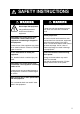
SAFETY INSTRUCTIONS WARNING ELECTRICAL SHOCK HAZARD WARNING Keep heater away from equipment. Do not open the equipment. Only qualified personnel should work inside the equipment. A heater can melt the equipment's power cord, which can cause fire or electrical shock. Use the proper fuse. Immediately turn off the power at the switchboard if water leaks into the equipment or something is dropped in the equipment. Continued use of the equipment can cause fire or electrical shock.
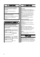
CAUTION Do not exceed 20 knots when operating the equipment and do not exceed 15 knots when lowering or raising the transducer. The transducer shaft may become damaged. CAUTION WORKING WITH THE SONAR OIL Precautions Keep oil away from eyes. Wear protective goggles when working with the oil. The oil can cause inflammation of the eyes. Do not touch the oil. Wear protective gloves when working with the oil. The oil can cause inflammation of the skin. Do not ingest the oil.
TABLE OF CONTENTS FOREWORD........................................................................................................................vi SYSTEM CONFIGURATION .............................................................................................viii 1. OPERATIONAL OVERVIEW........................................................................................1-1 1.1 1.2 1.3 1.4 1.5 1.6 1.7 1.8 Control Description ..........................................................................
TABLE OF CONTENTS 2.14 Interpreting the Horizontal Display .................................................................................... 2-25 2.14.1 How the horizontal mode picture is painted ........................................................... 2-25 2.14.2 Sample echo displays ............................................................................................ 2-26 2.14.3 Combination display examples ..............................................................................
TABLE OF CONTENTS 5. MENU OPERATION .....................................................................................................5-1 5.1 5.2 5.3 5.4 COM1 Menu ........................................................................................................................ 5-1 5.1.1 Displaying the COM1 menu ..................................................................................... 5-1 5.1.2 COM1 menu description...................................................................
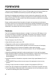
FOREWORD Thank you for purchasing the CH-270 Color LCD Searchlight Sonar. We are confident you will discover why FURUNO has become synonymous with quality and reliability. Dedicated in the design and manufacture of marine electronics equipment for more than half a century, FURUNO Electric Company has gained an unrivaled reputation as a world leader in the industry. This is the result of our technical excellence as well as our worldwide distribution and service network.
FOREWORD Usage Precautions • The Motion Sensor MS-100 compensates for ship’s pitching and rolling. However, it does not compensate for load unbalance. Use Clinometer BS-704 if compensation for load unbalance is required. • If the equipment will not be used for a long time, shut off the power to it at the mains switchboard to prevent battery discharge. • If the soundome is to be operated while the ship is dry-docked, set the transmitter output power to “MIN(imum),” on the COM1 menu.
SYSTEM CONFIGURATION CH-270 (350 stroke) INTERFACE UNIT IF-8000 DISPLAY UNIT MU-100C Navigator Control Unit Display Unit External Monitor XDR GAIN Remote Controller SECTOR RANGE TRAIN MAIN SUB POWER DISPLAY MODE FULL HALF TILT FAST SCAN BRILL TARGET MENU R/B EVENT CUSTOM MODE CONTROL UNIT CH-252 HULL UNIT SPEAKER 12-32VDC DATA/VIDEO OUT MOTION SENSOR Speaker TRANSCEIVER UNIT CH-273 12-32 VDC Motion Sensor Note 1: The CH-270 is supplied with or without a display unit.
SYSTEM CONFIGURATION CH-270 (250 stroke) INTERFACE UNIT IF-8000 DISPLAY UNIT MU-100C Navigator Control Unit DIsplay Unit External Monitor Remote Controller CONTROL UNIT CH-252 HULL UNIT SPEAKER 12-32VDC DATA/VIDEO OUT MOTION SENSOR TRANSCEIVER UNIT CH-273 CONTROL BOX Speaker 12-32 VDC Motion Sensor Note 1: The CH-270 is supplied with or without a display unit. For connection of locally supplied monitor, an interface unit is provided.
SYSTEM CONFIGURATION (This page intentionally left blank.
1. OPERATIONAL OVERVIEW 1.1 Control Description Chooses center bearing of training sector. Chooses detection range. Switches training sector between 180° and 360°. (horizontal mode), or 180° (vertical scan mode). Turns the power on/off. Chooses scan speed (sonar)/picture advancement speed (echo sounder). Raises the transducer. = Controls tilt angle. = Selects center direction of Adjusts receiver sensitivity. the vertical scanning sector. Chooses width of training sector. Turns target lock on/off.
1. OPERATIONAL OVERVIEW 1.2 Remote Controller The Remote Controller CH-256 (option) provides armchair control over range, tilt, target lock and training range. Choose display range. Choose tilt angle. Chooses training range. for full circle 360° (horizontal mode) or half circle 180° (vertical scan mode). Enables/disables target lock. Remote controller Note: The remote controller can also be used with a commercial monitor.
1. OPERATIONAL OVERVIEW 1.3 Turning the Power On/Off 1.3.1 Power on Press the [POWER] switch on the control unit until you hear a “click.” A beep sounds, the lamp above the switch lights and the startup display appears (for four seconds). MODEL : CH-270 180kHz Startup display Note 1: Wait at least five seconds before reapplying the power. Note 2: The first time the power is applied after installation, the language selection screen appears.
1. OPERATIONAL OVERVIEW 1.3.2 Power off 1. Press the [©] switch on the control unit. The lamp above the switch blinks while the transducer is being raised and lights steadily when it is fully raised. 30 25 Transducer status indicator • Up arrow is filled when transducer has been retracted into the tank. • Down arrow is filled when transducer has been fully lowered. • Appropriate arrow flashes during raising/lowering of transducer.
1. OPERATIONAL OVERVIEW 1.4 Raising, Lowering the Transducer 1.4.1 Lowering the transducer With the boat at the fishing ground, press the [ª] switch to lower the transducer. The lamp above the switch blinks while the transducer is being lowered and lights when it is completely lowered. The down arrow on the transducer status indicator is filled when the transducer is completely lowered.
1. OPERATIONAL OVERVIEW 1.5 Choosing a Display This sonar has eight display modes and you may choose one with one of the DISPLAY MODE keys. Refer to the chapter shown in the illustration for more information about each mode. Key Picture Key Picture NAV DATA HORIZONTAL NAV DATA HORIZONTAL EXPANSION This mode provides 360 degree coverage. Useful for general search. (Chapter 2) Zoomed horizontal picture appears over the entire screen.
1. OPERATIONAL OVERVIEW 1.6 Adjusting Screen Brilliance, Panel Dimmer Screen brilliance can be adjusted in nine levels and the panel dimmer (backlighting) in four. 1. Press the [BRILL] key to open the dialog box for screen brilliance and panel dimmer. Do the next step within four seconds; otherwise the dialog box will be erased. BRILL:3 DIMMER:3 Brilliance, panel dimmer dialog box 2. Operate ◄ or ► to adjust screen brilliance (0 is the lowest brilliance; 9 the highest).
1. OPERATIONAL OVERVIEW 1.8 Basic Menu Operation The menu, consisting of seven menus, mostly contains items which once preset do not require frequent adjustment. Below is the procedure for basic menu operation. 1. Press the [MENU] key to open the menu. The last-used menu is displayed. (In the example below, the COM2 menu is shown.) Note: Either PRESET or SHORT-CUT appears between ES and SYS at the top of the menu depending on the setting of CUSTOM KEY on the SYSTEM SETTING 1 menu.
2. HORIZONTAL MODE 2.1 Operational Overview The figure below shows the typical horizontal mode operating sequence. 7. Set center bearing of train sector. 6(a). Set scanning sector. 8. Set tilt angle. 5. Set range. 1. Turn on the power. 11. Adjust menu settings 9. Adjust gain. (ex. TVG) as required. XDR GAIN SECTOR POWER DISPLAY MODE 2. Lower the transducer. RANGE TRAIN TILT MAIN FULL FAST SUB HALF SCAN BRILL TARGET MENU R/B EVENT CUSTOM MODE 10.
2. HORIZONTAL MODE 2.2 Typical Horizontal Mode Display Tilt angle indicator (Indicates transducer tilt angle.) Horizontal max. range 30 Range and bearing markers Vertical max. depth Demonstration mode Cursor data Bottom echo Bearing marker Fish echo ETA marker Own ship marker Range marker 16 13 B208° + 25 Tilt angle Tilt angle Sector marker Interference Train indicator (DEMO) Range rejector R T N Depth marker (See note below.
2. HORIZONTAL MODE 2.3 Choosing the Range The [RANGE] control chooses the detection (display) range. Choose the range according to either the fish species being searched or the depth desired. 15 ranges are available. SEA SURFACE SEA SURFACE Range indicated onRange the screen. indicated on the screen. BOTTOM BOTTOM How to choose the range Default horizontal mode range settings Range No.
2. HORIZONTAL MODE 2.4 Choosing Sector Width Sector means the width of the transducer training. The [SECTOR] control chooses the training (display) area among the sixteen positions shown in the table below. Clockwise rotation of the control increases the sector width; counterclockwise rotation decreases it.
2. HORIZONTAL MODE 2.5 Choosing Train Center The [TRAIN] control chooses the center direction of the detection range. The range of adjustment is 0° to 354° in increments of 6°. The chosen bearing is shown with a filled circle, the train indicator, on the bearing scale. 0° (360°) → 6° → 12° → 18° → ...
2. HORIZONTAL MODE 2.6 Choosing the Tilt Angle 2.6.1 Choosing the tilt angle The tilt angle shows the direction to which the sound wave is emitted. When the sound wave is emitted horizontally, the tilt angle is said to be 0° and when emitted vertically, 90°. To set a tilt angle, operate the [TILT] control. Watch the tilt angle indication and the tilt angle indicator at the top right corner of the screen. The tilt angle can be set in increments of 1°, from +5° (upward) to 90° (downward).
2. HORIZONTAL MODE 2.6.2 Relation between tilt angle and echo Refer to the illustration below to see the relation between tilt angle and bottom echo. Case 1: Tilt angle 30°° to 40°: °: This tilt angle will display the entire bottom since it is captured by the full width of the beam. Case 2: Tilt angle 10°° to 20°: °: This tilt angle will only display half the bottom since it is only captured by the lower half of the beam.
2. HORIZONTAL MODE Points to consider • Normally, a vertically distributed fish school is a better sonar target than the bottom, because it reflects the transmitted pulse back toward the transducer. • In case 3, both fish schools “a” and “b” are presented. Generally speaking, however, midwater fish schools tend to be larger than bottom fish schools and they are often displayed near the bottom on the display. • It is difficult to detect bottom fish when they are not distributed vertically. 2.6.
2. HORIZONTAL MODE 2.6.4 Suitable tilt angle The figure below illustrates the relationship among tilt angle, depth and detection range. Refer to it to find out the suitable tilt angle for a given depth/detection range.
2. HORIZONTAL MODE 2.7 Choosing the Training Speed The training speed determines how fast the transducer scans the sounding sector. Two choices are available, normal speed and high speed, and one may be chosen with the [FAST SCAN] key. Each time the key is pressed, “NORM” (normal speed) or “FAST” (high speed) momentarily appears at the screen top. Normal (6°): 60 transmissions required to complete the full 360° picture. High (12°): 30 transmissions required to complete the full 360° picture.
2. HORIZONTAL MODE 2.9 Event Marker The event marker functions to mark important locations on the screen, and five may be inscribed. Each time the [EVENT] key is pressed the “latest event marker” (⊕) is inscribed at the cursor location and all previously entered event markers are shown by the “previous event marker” (+). When the capacity for event markers is reached, the eldest event marker is erased from the screen to make room for the latest.
2. HORIZONTAL MODE 2.9.2 Deleting all event markers All event markers can be erased from the screen as follows: 1. Operate the Omnipad to place the cursor outside the display area. 2. Press the [EVENT] key to show the following dialog box. Do the next step within four seconds; otherwise the dialog box will be erased. DELETE EVENT MARK? NO YES 3. Press ► to choose YES and then press the [MENU] key. All event markers are then erased from the screen. 2.
2. HORIZONTAL MODE 2.11 Adjusting the Picture 2.11.1 Suppressing bottom and surface reflections In shallow fishing grounds, excessive sea surface and bottom reflections often interfere with wanted fish echoes and they cannot be eliminated sufficiently with the TVG controls. In such cases, try to reduce the output power, without turning down the gain. The picture becomes clearer when output power is reduced rather than when the gain is decreased. 1. Press the [MENU] key to open the menu. 2.
2. HORIZONTAL MODE 2.11.2 Suppressing bottom tail As described earlier, fish schools near the bottom are sometimes difficult to detect because you have to discriminate fish echoes from the bottom reflections. To discriminate fish echoes near the bottom, choose the short Tx pulselength on the COM1 menu to decrease the tail of bottom reflections. 1. Press the [MENU] key to open the menu. 2. Press ▲ to choose MENU and then press ◄ to choose the COM1 menu. 3.
2. HORIZONTAL MODE To adjust TVG: 1. Press the [MENU] key to open the menu. 2. Press ▲ to choose MENU and then press ◄ or ► to choose HORZ. COM1 MENU COM2 TVG LEVEL TVG DISTANCE GAIN ADJUST RES. COLOR CLUTTER TARGET KEY 4.0 4.0 0 LOG 0 REVERSE LOCK MODE AUTO TILT AUTO OFF : SELECT HORZ VERT : CHANGE ES PRESET SYS MENU: END HORZ menu 3. Press ▲ or ▼ to choose TVG DISTANCE and then press ►. The following dialog box appears. TVG DISTANCE 4.0 GAIN Hi Lo 200 m 4.
2. HORIZONTAL MODE 5. Press the [MENU] key to register your selection and close the menu. 6. To suppress reflections from the sea surface or plankton, choose TVG LEVEL and then press ►. TVG LEVEL 4.0 GAIN Hi Lo 200 m 7. Press ◄ or ► to adjust TVG LEVEL, considering sea conditions. The setting range is 0 to 10, however a setting between 2.0 and 5.0 should provide satisfactory results. The higher the figure the less the gain over distance. 8.
2. HORIZONTAL MODE 2.11.4 Erasing weak echoes Weak echoes such as interference can be erased from the screen. This is useful when you want to observe a fish school echo. 1. Press the [MENU] key to open the menu. 2. Press ▲ to choose MENU. 3. Press ◄ or ► to choose COM2. COM1 MENU DELETING TRACK WHITE MARKER SIG LEVEL COLOR BKGD COLOR COM2 ES SHORT-CUT SYS NO OFF OFF 16 2 : CHANGE : SELECT HORZ VERT MENU: END COM 2 menu 4. Press ▲ or ▼ to choose SIG LEVEL. 5. Press ► to open the dialog box.
2. HORIZONTAL MODE 2.11.5 Enlarging fish echoes (horizontal expansion display) Fish echoes may be enlarged by using the horizontal expansion display. Press the key to show the horizontal expansion display. The direction of expansion depends on the train direction as shown in the table below.
2. HORIZONTAL MODE 2.12 Target Lock Three types of target lock modes are available. Manual reverse: The transducer train direction is reserved manually. This is the default target lock function setting and it may be used in both horizontal and vertical scan modes. Position: Tracks stationary position (such as a reef) using position data from a navigator. Available in the horizontal mode. Echo: Tracks fish echo either manually or automatically. Available in the horizontal mode. 2.12.
2. HORIZONTAL MODE 2.12.3 Position mode This mode tracks a stationary position (such as a reef) using position data fed from a navigator. Note 1: If the [TARGET] key is operated when using the horizontal/vertical scan combination mode, the train angle is automatically pointed toward target direction while the target lock marker is displayed. When target lock is canceled the previously used train angle is restored. Further, vertical search (see paragraph 5.3.
2. HORIZONTAL MODE 2.12.4 Echo mode The echo mode tracks a fish school, either automatically or manually. The default setting is automatic, and you can choose automatic or manual with “LOCK MODE” in the HORZ menu. Automatic echo tracking mode The automatic echo target lock function automatically tracks a fish school appearing in the operator-chosen target lock area.
2. HORIZONTAL MODE When the fish echo is lost the tilt angle is automatically changed as below to continue tracking the echo: Tilt changed to search [(A + 10°) → (A - 10°) →A] Detection area displayed once again and target lock indicator lights. A: Tilt angle at start of target lock 5. To turn off the target lock, press the [TARGET] key again.
2. HORIZONTAL MODE 2.13 Horizontal Menu Overview This section presents an overview of the items on the HORZ menu. 1. Press the [MENU] key to open the menu. 2. Press ▲ to choose MENU and then press ◄ or ► to choose the HORZ menu. MENU COM1 COM2 TVG LEVEL TVG DISTANCE GAIN ADJUST RES. COLOR CLUTTER TARGET KEY 4.0 4.
2. HORIZONTAL MODE CLUTTER: Low intensity echoes, often caused by sediments in water, are painted on the screen as a large number or random dots. This noise can be suppressed. The higher the number (setting) the weaker the echoes which are erased. TARGET KEY: Chooses target lock function among reverse, position and echo. For further details, see paragraph 2.12. LOCK MODE: Chooses how to track fish echo in “echo” target lock, automatically or manually. For further details, see paragraph 2.12.
2. HORIZONTAL MODE 2.14 Interpreting the Horizontal Display This section provides information necessary for interpreting the horizontal display. 2.14.1 How the horizontal mode picture is painted As shown below, the search beam is emitted from the soundome at a certain tilt angle. The information (target echoes) obtained by this beam is displayed in 6° (or 12°) sectors on the screen. With training through the entire area, a large cone shape area is formed, providing continuous pictures on the display.
2. HORIZONTAL MODE 2.14.2 Sample echo displays Bottom echoes When the tilt angle is changed, the bottom echo illustrated below will appear on the display. When the tilt is decreased (toward 0°), the bottom trace becomes wider and weaker. By observing the bottom condition on the display, you can prevent damage to the net. (A) Flat bottom Tilt angle: 10° to 15° Decreased tilt angle Only half of vertical beam width captures the bottom.
2. HORIZONTAL MODE Fish schools A fish school appears as a mass of echoes on the screen. The color of the mass shows the density of fish schools on the sonar beam. To find distribution and center point of a fish school, try several different tilt angles. (A) Sea surface fish Tilt angle: 0° to 10° Fish school Bottom echo not displayed because of decreased tilt angle. Sea surface reflections are present.
2. HORIZONTAL MODE Sea surface reflections To reduce sea surface reflections, set the tilt angle to 5° or lower, so the upper edge of the sonar beam does not hit the sea surface, or adjust TVG. When a decreased tilt angle is used, sea surface reflections cover a large area as illustrated below.
2. HORIZONTAL MODE Sidelobe echo (false echo) An ultrasonic wave is emitted in the direction set by the [TILT] control (main beam), however there are some emissions outside the main beam. These are called sidelobes. The energy of the sidelobe is fairly weak but when the water is comparatively shallow and the bottom is rocky and hard, strong signals are detected by the sidelobe. These are represented on the display as a false echo as shown below.
2. HORIZONTAL MODE 2.14.3 Combination display examples Horizontal/history display key to display the horizontal/history display. Press the Tilt angle Cursor position data Tilt angle indicator Range →17 ↓ 14 B148° + R 40 m T 40° 30 Interference rej. ON Target lock indicator 25 Own ship marker 34° 12. 343' N 134° 34. 213' W CSE 357° SPD 9.
2. HORIZONTAL MODE Horizontal/video plotter display Press the key to display the horizontal/video plotter display. Tilt angle Cursor position data Tilt angle indicator Range →18 ↓ 15 B154° + R 40 m T 40° 30 Interference rej. ON Target lock indicator 25 Transducer status indicator Own ship marker 34° 12. 343' N 134° 34. 213' W Train position CSE 357° SPD 9.9 kt Position in latitude and longitude* Course*, speed* Sonar range marker (Radius changes with video plotter range.
2. HORIZONTAL MODE Horizontal/strata display key to display the horizontal/strata display. Press the Tilt angle Cursor position data Tilt angle indicator Range →12 ↓ 10 B133° + R 40 m T 40° 30 Interference rej. ON Target lock indicator 25 Own ship marker Transducer status indicator 34° 12. 343' N 134° 34. 213' W CSE 357° SPD 9.9 kt Train position PORT Position in latitude and longitude* Course*, speed* STBD Number of lines increases by one with each train.
2. HORIZONTAL MODE Color bar for the strata display The depth of the bottom each in all directions is displayed in the sub window, in the colors set by the color bar for the strata display. The color bar for the strata display shows search angle range below 336 degrees. Strongest color Weakest color -90˚ -18˚ -12˚ -6˚ 0˚ 6˚ 12˚ 18˚ 90˚ The undulation of the bottom echo in all directions is shown by the colors on the color bar for the strata display.
2. HORIZONTAL MODE Projection in fore direction and strata display Color "b" on the color bar is displayed here.
3. VERTICAL SCAN MODE 3.1 Operational Overview The figure below shows the typical vertical scan mode operating sequence. 6. Set center bearing of train sector. 7(a). Set scanning sector. 1. Turn on the power. 8. Set tilt angle. 5. Set range. 11. Adjust menu settings 9. Adjust gain. (ex. TVG) as required. XDR GAIN SECTOR RANGE TRAIN POWER DISPLAY MODE TILT MAIN FULL FAST SUB HALF SCAN BRILL TARGET MENU R/B EVENT CUSTOM MODE 2. Lower the transducer. 4. Select appropriate 10.
3. VERTICAL SCAN MODE 3.2 Displaying Vertical Scan Mode Display 3.2.1 Typical vertical scan mode display Press the key to show the vertical scan mode display. Bearing indicator (Shows training direction.
3. VERTICAL SCAN MODE 3.2.2 How the vertical scan picture is painted The sounding beam is emitted and the information (target echoes) obtained by the reflected echo appears in the corresponding sector as it appears on the horizontal mode. The difference is that the training is performed only in vertical direction. It forms a sounding area of a half-circle (like a slice of watermelon) to observe a vertical section of underwater conditions. Note: The tilt mechanism has a 90° range of movement.
3. VERTICAL SCAN MODE 3.2.3 Horizontal/vertical scan display Press the key to display the horizontal/vertical scan display. Tilt angle Cursor position data Vertical scan bearing cursor →17 ↓ 14 B156° + Tilt angle indicator Range R 40 m T 40° 30 Interference rejector ON Target lock indicator 25 Transducer status indicator Own ship marker 34° 12. 343' N 134° 34. 213' W CSE 357° SPD 9.9 KT Train position AFT FORE Position in latitude, and longitude* Course*, speed* * Requires navigator.
3. VERTICAL SCAN MODE The displays are independent of each other so you can adjust them as desired. Press the [MAIN/SUB] key to choose the window to adjust. Each press of the key momentarily displays MAIN WINDOW CONTROLLABLE or SUB WINDOW CONTROLLABLE at the top of the screen to let you know which window may be adjusted. A red rectangle circumscribes the sub window when it is selected. The following controls are operative from either window: SECTOR, TRAIN, RANGE, TILT, FAST SCAN, FULL/HALF and CUSTOM MODE.
3. VERTICAL SCAN MODE 3.3 Choosing the Range The [RANGE] control chooses the detection (display) range, in 15 settings. Choose the range according to either the fish species being searched or the depth desired. Each time the control is operated the newly chosen range briefly appears in large characters at the screen top. Range is permanently displayed at the top right-hand corner of the screen.
3. VERTICAL SCAN MODE 3.5 Choosing Display Sector Sector means the width of the transducer training, from 6° to 180°. Sector (Shown: 24°) 24° Sector The [SECTOR] control chooses the training area among the sixteen positions shown in the table below. Clockwise rotation of the control increases the sector width; counterclockwise rotation decreases it.
3. VERTICAL SCAN MODE 3.6 Choosing Sector Center The center direction of the sounding beam in the vertical direction can be changed with the [TILT] control. The setting range is 0° to 180° in increments of 6°. Choose the setting which places the sector center in the middle of the detection range. Sector center angle set with TILT control PORT In the example display at left, the sector center indicator is starboard, and the width of the sector is 48°.
3. VERTICAL SCAN MODE 3.7 Choosing the Tilt Speed The [FAST SCAN] key chooses the tilt speed; that is, the stepping angle at which the transducer scans. Two choices are available, 3° (normal speed) and 6° (high speed). Each time the key is pressed the display momentarily shows “NORM” (normal speed) or “FAST” (high speed). Normal: 60 transmissions to complete a half circle, in increments of 3°. High: 30 transmissions to complete a half circle, in increments of 6°.
3. VERTICAL SCAN MODE 3.9 Event Marker 3.9.1 Entering an event marker The event marker functions to mark important locations on the screen, and five may be inscribed. Each time the [EVENT] key is pressed the “latest event marker” (⊕) is inscribed at the cursor location and all previously entered event markers are shown by the “previous event marker” (+). When the capacity for event markers is reached, the eldest event marker is erased from the screen to make room for the latest.
3. VERTICAL SCAN MODE 3.9.2 Deleting all event markers All event markers can be erased from the screen as follows: 1. Operate the Omnipad to place the cursor outside the display area. 2. Press the [EVENT] key to show the following dialog box. Do the next step within four seconds; otherwise the dialog box will be erased. DELETE EVENT MARK? NO YES 3. Press ► to choose YES and then press the [MENU] key. All event markers are erased from the screen. 3.
3. VERTICAL SCAN MODE 3.11 Adjusting the Picture 3.11.1 Displaying weak echoes clearly Echoes from targets (such as the bottom or a fish) return to the transducer in order of the distance to them, and when their intensities are compared at the transducer face, those from nearer targets are generally stronger when their reflecting properties are nearly equal.
3. VERTICAL SCAN MODE 4. Press ◄ or ► to adjust TVG distance, considering sea conditions. The larger the figure the greater the distance at which the TVG works. TVG Distance Setting Meters 0 0.5 1.0 1.5 2.0 2.5 3.0 3.5 4.0 4.5 5.0 .... 10.0 3 8 20 40 60 100 130 160 200 250 320 .... 1000 Feet 10 30 70 130 210 330 410 520 660 820 1040 3280 Passi/braza 2 5 10 20 40 60 80 100 120 150 180 600 5 10 20 40 60 80 100 110 140 170 550 Fathoms 5.
3. VERTICAL SCAN MODE 3.11.2 Suppressing noise and interference You may encounter occasional or intermittent noise and interference as shown below. This is mostly caused by electrical equipment, engine, propeller noise from own ship, or noise from other sonars being operated nearby. If interference appears, turn on the interference rejector as below to suppress it. Interference rejector ON Interference (In this display, interference shows itself every 6°.) Appearance of interference 1.
3. VERTICAL SCAN MODE 3.11.4 Resolution color RES. COLOR sets transfer characteristics of input signal level versus display echo level. Echo strength is emphasized in order of CUBE, SQUARE, LINEAR, LOG. You can see the characteristics of each by watching the color bar as you change the setting. 1. Press the [MENU] key to open the menu. 2. Press ▲ to choose MENU at the top of the screen. 3. Press ◄ or ► to choose the VERT menu. 4. Press ▲ or ▼ to choose RES. COLOR. 5. Press ► to open the dialog box. 6.
3. VERTICAL SCAN MODE 3.11.6 Choosing horizontal range expansion factor You may choose the horizontal range expansion factor for the vertical scan picture, from x1 or x2. Note that this feature cannot be adjusted when the vertical search mode, activated by a function key, is turned on. 1. Press the [MENU] key to open the menu. 2. Press ▲ to choose MENU at the top of the screen. 3. Press ◄ or ► to choose the VERT menu. 4. Press ▲ or ▼ to choose HORZ RANGE. 5. Press ► to open the dialog box. 6.
3. VERTICAL SCAN MODE 3.12 Interpreting the Vertical Scan Display This section provides information necessary for interpreting the vertical scan display. 3.12.1 Sample echo displays Port-starboard picture You can see fish echoes at the center-right of the screen. The bottom is displayed wider as the distance from the ship’s position increases. Therefore, it may be difficult to discriminate bottom fish.
3. VERTICAL SCAN MODE Display of net hauling This is an example of net hauling display. The location of the net is indicated clearly. FORE AFT Net Net hauling and sonar picture False echo In shallow water (depth less than 100 m) detection, unwanted echoes as shown in the figure below may appear. This phenomenon is caused by the false echo from the previous transmission. Reducing the Tx rate on the COM1 menu may lessen this effect.
4. ECHO SOUNDER MODE 4.1 Operational Overview The figure below shows the typical echo sounder mode operating sequence. 8. Set tilt angle. 7. Select display sector. 5. Set range. 11. Adjust menu settings (turn on A-scope display, etc.). 1. Turn on the power. 6. Adjust gain. XDR GAIN SECTOR RANGE TRAIN POWER TILT MAIN FULL FAST SUB HALF SCAN DISPLAY MODE BRILL TARGET MENU R/B EVENT CUSTOM MODE 2. Lower the transducer. 4. Select echo sounder mode. 9. Set picture advance speed.
4. ECHO SOUNDER MODE 4.2 Typical Echo Sounder Display Press the key to display the echo sounder picture. Tilt angle indicator Bearing (Shows tilt angle of transducer.) indicator (Shows train Tilt angle direction.) Interference rejector ON Range Heading Cursor position + 4 ↓ 340° Transducer status indication R 10 m T 60° Minute marker 34° 12. 343' N 134° 34. 213' W Fish echo Cursor Range CSE SPD 357˚ 9.9 kt CUR 11.0˚ 2.0 kt GAIN 5.3 5 5 Bottom echo TVG LEVEL 4.
4. ECHO SOUNDER MODE 4.3 Choosing the Range The [RANGE] control chooses the detection (display) range, in 15 settings. Choose the range according to either the fish species being searched or the depth desired. Each time the control is operated the newly chosen range briefly appears in large characters at the screen top. Range is permanently displayed at the top right-hand corner. Normally the range is set so that the bottom is traced at the lower part of the screen.
4. ECHO SOUNDER MODE 4.4 Train Direction The sounding beam may be directed 360° in any direction. Operate the [TRAIN] control to choose sounding beam direction. Each setting on the control is an increment of 6°. The train indicator at the top of the screen shows training direction: 0°, fore direction; 90°, starboard direction; 180°, aft direction, and 270°, port direction. 0° (360°) → 6° → 12° → 18° → ... 354° Train 0° Train 90° Train 180° Train 270° Train indicator and display 4.
4. ECHO SOUNDER MODE 4.7 Measuring Range by Cursor Use the cursor to display the range from own ship to the cursor location. Use the Omnipad to place the cursor where desired. The range to the cursor appears at the upper left-hand corner of the screen. ↓ Range to cursor : Range NAV DATA or A-SCOPE DISPLAY Depth, Water Temp. Display Cursor How to measure range with the cursor 4.8 Event Marker The event marker functions to mark important locations on the screen, and five may be inscribed.
4. ECHO SOUNDER MODE 4.8.1 Inscribing the event marker 1. Operate the Omnipad to place the cursor on the location desired for an event marker. 2. Press the [EVENT] key to inscribe the event marker. Display area "Previous event marker" NAV DATA or A-SCOPE DISPLAY Depth, Water Temp. Display "Latest event marker" To delete all event markers, place the cursor outside the display area and press the [EVENT] key. How to inscribe and delete the event markers 4.8.
4. ECHO SOUNDER MODE 4.9 Range Marker The range marker functions to measure the range to a target echo (fish school, bottom, etc.) 1. Operate the Omnipad to place the cursor on the location desired. 2. Press the [R/B] key to display the range marker. The range marker appears along with range indication. 3. To erase the range marker, place the cursor on the marker or outside the display area and then press the [R/B] key. Range marker Range 67 NAV DATA or A-SCOPE DISPLAY Depth, Water Temp.
4. ECHO SOUNDER MODE 4.10 Adjusting the Picture 4.10.1 Displaying weak echoes clearly Echoes from targets (such as the bottom or a fish) return to the transducer in order of the distance to them, and when their intensities are compared at the transducer face, those from nearer targets are generally stronger when their reflecting properties are nearly equal.
4. ECHO SOUNDER MODE 3. Press ▲ or ▼ to choose TVG DISTANCE and then press ►. The following dialog box appears. 4.0 TVG DISTANCE GAIN Hi Lo 200 m 4. Press ◄ or ► to adjust TVG distance. TVG Distance Setting 0 0.5 1.0 1.5 Meters 3 8 20 40 60 100 130 160 200 Feet 10 30 70 130 210 330 410 520 660 Passi/braza 2 5 10 20 40 60 80 100 120 5 10 20 40 60 80 100 110 Fathoms 2.0 2.5 3.0 3.5 4.0 5.0 .... 10.0 250 320 ....
4. ECHO SOUNDER MODE 4.10.2 Finding echo strength (A-scope display) The A-scope display shows echoes at each transmission with amplitudes and tone proportional to their intensities, on the right 1/4 of the screen. It is useful for estimating the kind of fish school and bottom composition. 1. Press the [MENU] key. 2. Press ▲ to choose MENU. 3. Press ◄ or ► to choose ES. 4. Press ▼ to choose A-SCOPE. 5. Press ◄ or ► to open the dialog box. A-SCOPE OFF ON 6. Press ► to choose ON. 7.
4. ECHO SOUNDER MODE 4.10.3 Gain adjustment Adjust the gain here when there is disparity in gain level between the main and sub windows. 1. Press the [MENU] key to open the menu. 2. Press ▲ to choose MENU at the top of the screen. 3. Press ◄ or ► to choose the ES menu. 4. Press ▲ or ▼ to choose GAIN ADJUST. 5. Press ► to open the dialog box. 6. Press ◄ or ► to adjust. 7. Press the [MENU] key to register your selection and close the menu. 4.10.4 Resolution color RES.
4. ECHO SOUNDER MODE 4.10.5 Suppressing clutter Low intensity echoes, often caused by sediments in water, are painted on the screen as a large number or random dots. This noise can be suppressed. 1. Press the [MENU] key to open the menu. 2. Press ▲ to choose MENU at the top of the screen. 3. Press ◄ or ► to choose the ES menu. 4. Press ▲ or ▼ to choose CLUTTER. 5. Press ► to open the dialog box. 6. Press ◄ or ► to choose 0, 1, 2 or 3 as appropriate.
5. MENU OPERATION 5.1 COM1 Menu 5.1.1 Displaying the COM1 menu 1. Press the [MENU] key to open the menu. 2. Press ▲ to choose MENU, and then press ◄ to choose COM1. MENU COM1 COM2 TX POWER PULSELENGTH TX RATE INT REJECT AGC MAX LONG 10 OFF OFF AUDIO LEVEL 0 : SELECT : CHANGE HORZ VERT ES PRESET SYS MENU: END COM1 menu 5.1.2 COM1 menu description TX POWER: Chooses transmitter output power to maximum or minimum. For further details, see paragraph 2.11.1.
5. MENU OPERATION 5.2 COM2 Menu 5.2.1 Displaying the COM2 menu 1. Press the [MENU] key to open the menu. 2. Press ▲ to choose MENU, and then press ◄ or ► to choose COM2. COM1 MENU DELETING TRACK WHITE MARKER SIG LEVEL COLOR BKGD COLOR : SELECT COM2 HORZ VERT ES PRESET SYS NO OFF OFF 16 2 : CHANGE MENU: END COM2 menu 5.2.2 COM2 menu description DELETING TRACK: Choose ON to delete all ship’s track (from horizontal and horizontal/video plotter displays).
5. MENU OPERATION 5.3 Short-cut Menu, Preset Menu These menus program the CUSTOM MODE keys [1], [2] and [3]. The menu to use may be chosen with CUSTOM KEY on the SYSTEM SETTING 1 menu. Short-cut key: One-touch activation of the operator-selected dialog box. Preset key: One-touch setup of mode, sector, train, range, tilt and scan speed. Below are the default settings for PRESET.
5. MENU OPERATION ** SYSTEM MENU ** SYSTEM SETTING: RANGE-SONAR MODE RANGE-VERTICAL MODE RANGE-E/S MODE RANGE-TRACK MODE COLOR PALETTE LANGUAGE SYSTEM BACKUP LOAD BACKUP DATA HEADING OFFSET, DRAFT OFFSET ADJ MOTION SENSOR TX FREQ ADJUST TEST TEST PATTERN DEMO MODE DEFAULT : SELECT : MENU DISPLAY MENU: END System menu 5. SYSTEM SETTING is highlighted; press ► to open the SYSTEM SETTING menu.
5. MENU OPERATION 5.3.2 Changing setting of preset key 1. Choose PRESET KEY following the procedure in paragraph 5.3.1. 2. Press the [MENU] key to open the menu. 3. Press ▲ to choose MENU, and then press ◄ or ► to choose PRESET.
5. MENU OPERATION 5.3.3 Changing setting of short-cut key The default settings are key [1], vertical search; key [2], volume, and key [3], delete track. The operator may change their functions as desired. Note: In the combination modes the short-cut key may only be activated from the main window. 1. Choose SHORT-CUT following the procedure in paragraph 5.3.1. 2. Press the [MENU] key to open the menu. 3. Press ▲ to choose MENU, and then press ◄ or ► to choose SHORT-CUT.
5. MENU OPERATION Activating a short-cut key 1. Press a CUSTOM MODE key, and the dialog box programmed for the custom key pressed appears. (No dialog box appears for VER. SEARCH.) The dialog box below is for “CLUTTER”. CLUTTER (HORZ): 0 1 2 3 Note: Vertical search can only be activated when the horizontal mode or a combination mode is active. 2. Press ◄ or ► to choose option desired. 3. Press the [MENU] key to close the dialog box.
5. MENU OPERATION 5.4 SYSTEM Menu This menu provides items which may be set according to operator’s preference. 5.4.1 Displaying the SYSTEM menu 1. Press the [MENU] key to open the menu. 2. Press ▲ to choose MENU, and then press ► to choose SYS. 3. Press ▼ to choose GO TO SYS MENU. 4. Press ◄ to choose YES.
5. MENU OPERATION 5.4.2 SYSTEM SETTING 1 menu description 1. Display the SYSTEM menu and then press ▲ or ▼ to choose SYSTEM SETTING. 2. Press ► to open the SYSTEM SETTING menu. 3. Press ▲ to MENU. 4. Press ◄ to choose “1.
5. MENU OPERATION HEADING INDICATION: Chooses heading indication format, true (figures) or azimuth (compass points, for example, N, S, etc.), for the echo sounder and vertical scan modes. Requires heading data. NORTH MARK: Turns the north marker on or off. Requires heading data. CSE DATA: Chooses heading data source, navigator or gyrocompass, with which to draw ship’s track. For heading sensor or gyrocompass, choose “GYRO”.
5. MENU OPERATION 5.4.3 SYSTEM SETTING 2 menu description ** SYSTEM SETTING 2 ** MENU STABILIZER AUTO RETRACTION 1 : OFF : OFF 2 ON (OFF, 5-15kt) SPEED ALARM/MESSAGE : OFF 15 kt SWEEP INDICATOR : DOT LINE DEFAULT SETTING : NO YES 20kt MAXIMUM ALLOWABLE SPEED IS 15 KNOTS WHILE SOUNDDOME IS BEING RETRACTED. IF VESSEL HAS RAPID ACCELERATION CAPABILITIES, AUTO RETRACTION SETTINGS OF 10-12 KNOTS ARE MANDATORY TO AVOID CATASTROPHIC DAMAGE TO SOUNDOME ASSY. ANY PHYSICAL DAMAGE TO THE SOUNDOME ASSY.
5. MENU OPERATION SPEED ALARM MESSAGE: Choose the speed at which the speed alarm message is displayed and the aural alarm released when the speed goes higher than that set here. The audio alarm can be silenced with the [R/B] key. [ª] pressed to lower transducer Message 1 appears. Reduce speed below 15 kts to restore normal operation. Speed above 15 kts Transducer being lowered Speed over 15 kts Message 1 appears and lowering continues.
5. MENU OPERATION 5.4.4 Sonar (horizontal) mode range settings The user may preset horizontal mode ranges as desired. 1. Choose RANGE-SONAR MODE at the SYS menu and then press ►. ** RANGE-SONAR MODE ** 1 2 3 4 5 6 7 8 : : : : : : : : 10 (10-1600m) 20 40 60 80 100 120 160 9 : 200 10 11 12 13 14 15 : : : : : : 250 300 400 500 600 800 DEFAULT SETTING : : SELECT NO YES : CHANGE MENU: END Range-sonar mode menu 2. Press ▲ or ▼ to choose range number desired. 3. Press ◄ or ► to set range. 4.
5. MENU OPERATION 5.4.5 Vertical scan mode range settings As with the horizontal mode, the user may preset the vertical scan mode’s ranges. 1. Choose RANGE-VER MODE at the SYS menu and then press ►. ** RANGE-VER MODE ** 1 2 : : 10 (10-600m) 20 3 4 : : 30 40 5 6 : : 60 80 7 : 100 8 : 120 9 : 160 10 : 200 11 : 250 12 13 : : 300 400 14 15 : : 500 600 DEFAULT SETTING : : SELECT NO YES : CHANGE MENU: END Range-ver mode menu 2. Press ▲ or ▼ to choose range number desired. 3.
5. MENU OPERATION 5.4.6 Echo sounder mode range settings As with the horizontal and vertical scan modes, the user may preset the echo sounder mode’s ranges. 1. Choose RANGE-E/S MODE at the SYS menu and then press ►. ** RANGE-E/S MODE ** 1 2 : : 10 (10-600m) 20 3 4 : : 30 40 5 6 : : 60 80 7 : 100 8 : 120 9 : 160 10 : 200 11 : 250 12 13 : : 300 400 14 15 : : 500 600 DEFAULT SETTING : : SELECT NO YES : CHANGE MENU: END Range-E/S mode menu 2.
5. MENU OPERATION 5.4.7 Track range settings You may choose the video plotter display scale range as follows. 1. Choose RANGE-TRACK at the SYS menu and then press ►. ** RANGE-TRACK MODE ** 1 2 3 : : : 500 (100-10000m) 1000 2000 4 : 4000 5 : 8000 DEFAULT SETTING : : SELECT NO YES : CHANGE MENU: END Range-track mode menu 2. Press ▲ or ▼ to choose range number desired. 3. Press ◄ or ► to set. 4. Press the [MENU] key to register settings and close the menu.
5. MENU OPERATION 5.4.8 Color palette The color palette lets the user change the color of echoes, background, text and menu as desired. Cursor ** COLOR PALETTE ** 1 2 3 4 5 6 7 8 9 10 11 12 13 14 15 ECHO Arrow BKGD TEXT MENU BKGD TEXT MENU BKGD1 BKGD TEXT MENU BKGD3 BKGD2 COLOR : ECHO 1 R G B : : : DEFAULT SET : 0 2 9 NO : SELECT YES (ECHO & BKGD COLORS WILL BE CHANGED) : CHANGE MENU: END Color palette 1. Press ◄ or ► to place the cursor and arrow on the item to change.
5. MENU OPERATION 5.4.9 Language Menu language can be chosen from among the languages shown in the Language menu. ** LANGUAGE ** LANGUAGE: JAPANESE ITALIANO SVENSK : CHANGE MENU: END ENGLISH PORTUGUES THAI FRANCAIS DANSK ESPANOL NORSK Language menu 5.4.10 System backup System settings can be saved to the internal memory with the menu item SYSTEM BACKUP. ** SYSTEM BACKUP ** ARE YOU SURE? : NO YES NOTE: OVERWRITES PREVIOUS BACKUP DATA. : CHANGE MENU: END System backup menu 5.4.
5. MENU OPERATION 5.4.12 Transducer frequency adjustment If the CH-270 is receiving interference from a video sounder or other sonar on board your ship, adjust the frequency of the CH-270’s transducer to reduce the interference. ** TX FREQ ADJUST ** FREQ SHIFT : CHANGE : 180.0 kHz (171-189 kHz) MENU: END TX frequency adjustment menu 5.4.13 Demonstration mode The demonstration mode provides a simulated sonar picture to help you become acquainted with how your sonar works.
5. MENU OPERATION 5.4.14 Restoring all default settings All default menu settings may be restored. Choose YES and then press the [MENU] key to restore all default settings. Note that the settings stored in SYSTEM BACKUP are not disturbed. ** DEFAULT ** ARE YOU SURE? : NO YES NOTE: RESET ALL THE SETTINGS INCLUDED IN SYSTEM MENU TO DEFAULT. : CHANGE MENU: END Note: All default settings will be restored. If necessary jot down settings which must be restored.
6. MAINTENANCE, TROUBLESHOOTING This chapter provides the information necessary for keeping the equipment in good working order. WARNING Do not open the equipment. Hazardous voltage which can cause electrical shock exists inside the equipment. Only qualified personnel should work inside the equipment. 6.1 Preventive Maintenance Check the following points monthly. • • • • Check all cables. If damaged, replace. Check connectors at rear of each unit. Clean if necessary. Check earth of each unit.
6. MAINTENANCE, TROUBLESHOOTING 6.3 Hull Unit Maintenance 6.3.1 Lubrication Coat the raise/lower screw shaft once a year with Molytone grease. Also, grease the raise/lower main shaft (upper part of the grease cotton retainer) twice a year. 6.3.2 Manually raising, lowering transducer WARNING Turn off the power at the ship's mains switchboard before conducting the procedure below. Moving parts can cause bodily injury. Hull unit CH-181 1.
6. MAINTENANCE, TROUBLESHOOTING Hull unit CH-184 1. Turn off the breaker switch on the hull unit. 2. Slightly loosen the bolts fastening the shaft retainer. 3. Raise and lower the shaft by hand to confirm that it raises and lowers smoothly. If it does not rise or lower smoothly, do not use force; the shaft may bend. 4. Tighten bolts on shaft retainer. (Torque: 20-25 Nm) 5. Turn on the breaker switch. 6.
6. MAINTENANCE, TROUBLESHOOTING 6.6 Troubleshooting The table below provides common symptoms of equipment troubles and the means to rectify them. Symptom Cannot turn on the power. Check, Remedy • Check ship’s mains. • Have a suitably qualified technician check the fuse in the transceiver unit. Bottom echo becomes irregular. • Rough seas. Distance to the bottom changes due to rolling Weak echo • Output power set to minimum. Set to maximum, on the COM1 and pitching. • Long range chosen.
6. MAINTENANCE, TROUBLESHOOTING 6.7 Error Messages The table below shows the error messages which may appear on the display. All error messages are accompanied by the audio alarm, which you may silence with the [R/B] key. Message Raise/Lower Error RAISE/LOWER FUNCTION HAS NOT BEEN COMPLETED. MAXIMUM ALLOWABLE SPEED IS 15 KNOTS WHILE SOUNDOME IS BEING RETRACTED. PRESS R/B KEY TO SILENCE ALARM. Train Error TRAINING ERROR (CHECK HULL UNIT.) PRESS R/B KEY TO SILENCE ALARM. Tilt Error TILT ERROR.
6. MAINTENANCE, TROUBLESHOOTING 6.8 Diagnostics 1. Press the [MENU] key to open the menu. 2. Press ▲ to choose MENU, and then press ► to choose SYS. 3. Press ▼ to choose GO TO SYS MENU. 4. Press ◄ to choose YES. 5. Choose TEST and then press ► to start the test. The lamps above the XDR switches light alternately every second while the test display is shown. In a few moments after pressing ► the results of the test appear. MAIN PROGRAM NO. 0650109-**.** PANEL PROGRAM NO.
6. MAINTENANCE, TROUBLESHOOTING Interpreting the test results display MAIN PROGRAM NO., PANEL PROGRAM NO.: The program numbers of the MAIN and PANEL programs appear at the top of the display. ROM, RAM, VRAM, NMEA: Checked for proper operation and the results displayed as OK or NG (No Good). For NG contact a FURUNO agent or dealer for advice. TX FREQUENCY: Shows frequency of the transducer. ROLL and PITCH: These values change with ship’s pitching and rolling (range: -30° to +30°).
6. MAINTENANCE, TROUBLESHOOTING 6.9 Test Pattern A test pattern can be displayed to check for proper display of colors. 1. Press the [MENU] key to open the menu. 2. Press ▲ to choose MENU, and then press ► to choose SYS. 3. Press ▼ to choose GO TO SYS MENU. 4. Press ► to choose YES. 5. Choose TEST PATTERN and then press ► to display the test pattern. Press ► again to change the test pattern. The pattern changes in the sequence shown below with each press of ►.
MENU TREE [MENU] key COM1 menu TX POWER (MAX, MIN) PULSELENGTH (LONG, SHORT) TX RATE (EXTERNAL, 1-10; 10) INT REJECT (OFF, ON) DEFAULT SETTINGS AGC (OFF, ON) SHOWN IN BOLD ITALIC. AUDIO LEVEL (0-10) COM2 menu DELETING TRACK (NO, YES) WHITE MARKER (8-color: OFF, 1-7; 16-color: OFF, 1-15) SIG LEVEL (8-color: OFF, 1-6; 16-color: OFF, 1-14) COLOR (16, 8) BKGD COLOR (1, 2, 3) HORZ menu TVG LEVEL (0-10, 4.0) TVG DISTANCE (0-10, 4.0) GAIN ADJUST (-10 - +10, 0) RES.
MENU TREE (CONTINUED FROM PREVIOUS PAGE) SYSTEM menu SYSTEM SETTING SYSTEM SETTING 1 POSITION (SHIP'S L/L, SHIP'S LOP, CURSOR L/L) TRACK (OFF, ON) CURRENT DATA (OFF, FLOW FROM, FLOW TO) HEADING INDICATION (TRUE, AZ) NORTH MARK (OFF, ON) CSE DATA (NAV, GYRO) NAV DATA (GPS, LoranC, LoranA, DR, DECCA, OTHERS) TVG CORRECTION (OFF, 1/2, 1/1) UNIT (m, ft, fa, HIRO, P/B) TEMP (°C, °F) TARGET L/L (OFF, ON) CUSTOM KEY (PRESET KEY, SHORT-CUT KEY) EMPHASIS MODE (OFF, NORMAL, RED) ETA MARK (OFF, 10sec, 30sec, 1min, 3m
SPECIFICATIONS 1. GENERAL 1.1 Display System 1.2 1.3 1.4 Transmit Frequency Output Power Range (factory settings) 10.4-inch color LCD (640 x 480 dots), or locally supplied monitor 180 kHz 0.8 kW, power reduction available Range (m) 1 2 Horizontal Mode 3 4 5 6 10 20 Vertical Scan Mode 40 60 80 100 120 160 200 250 300 400 500 600 800 30 40 60 80 10 1.5 1.6 20 Output Pulse Length TVG 7 8 9 10 11 12 13 14 15 100 120 160 200 250 300 400 500 600 0.24 to 20.
SPECIFICATIONS 3.5 Horizontal Mode Control Scanning Angle: 6° to 360°, 24° step Scanning Center: 6° steps, 360° setting available Scanning Step Angle: Normal: 6°, High speed: 12° Elevation Angle: +5° to 90°, 1° step Time to Train Full Circle: Range (m) Time (sec) 3.
INDEX A AGC .............................................................5-1 A-scope display .........................................4-10 Auto retraction ...........................................5-11 Auto tilt.......................................................2-24 B Backup data...............................................5-18 BRILL key ....................................................1-7 Brilliance ......................................................1-7 C Clutter echo sounder mode...........
INDEX Menu tree .................................................AP-1 N North mark.................................................5-10 P Panel dimmer ..............................................1-7 Picture advance speed (echo sounder mode)...............................4-4 Position data format.......................................................5-9 source ....................................................5-10 POWER switch............................................1-3 Pulselength...................