Your Local Agent/Dealer 9-52 Ashihara-cho, Nishinomiya, Japan Telephone : 0798-65-2111 Telefax : 0798-65-4200 All rights reserved. Printed in Japan FIRST EDITION : FEB. 1997 C PUB.No. OME-72440 ( TATA ) CI-35/35H : MAY.
SAFETY INSTRUCTIONS "DANGER", "WARNING" and "CAUTION" notices appear throughout this manual. It is the responsibility of the operator of the equipment to read, understand and follow these notices. If you have any questions regarding these safety instructions, please contact a FURUNO agent or dealer. DANGER This notice indicates a potentially hazardous situation which, if not avoided, will result in death or serious injury.
WARNING CAUTION Do not open the cover of the equipment. Do not place liquid-filled containers on the top of the equipment. This equipment uses high voltage electricity which can shock, burn, or cause death. Only qualified personnel should work inside the equipment. Fire or electrical shock can result if a liquid spills into the equipment. Do not disassemble or modify the equipment. Fire, electrical shock or serious injury can result. Do not place heater near the equipment.
CONTENTS SAFETY INSTRUCTIONS ________________________________ i to ii TABLES FOR RECORDING USER PRESETS _______________ v to x CHAPTER 1. GENERAL _______________________________ 1-1 to 1-8 1. FEATURES ..................................................................................... 1-1 2. PRINCIPLE OF MEASUREMENT .................................................. 1-2 3. TIDE, NAV-TIDE & TIDE DIFFERENTIAL....................................... 1-5 CHAPTER 2.
TIDE VECTOR/COURSE PLOT SECTION ..................................... 3-10 to 3-15 TIDE VECTOR Display ...................................................................... 3-10 TIDE HISTORY Display ......................................................................3-11 COURSE PLOT Display .................................................................... 3-12 TIDE EFFECT Display ....................................................................... 3-13 DRIFT Display ................................
TABLES FOR RECORDING USER PRESETS The CI-30/35H provides menus to preset, various measuring and display conditions to customize the equipment precisely for your operating conditions. The form below is provided to record user presets, so they can be restored in the event of loss by misoperation or by maintenance/service work. 1) BASIC MENU (Display/measuring conditions) [MENU 1] USER PRESET ITEM * : selected FAC.
USER PRESET ITEM : selected FAC. SETTING TIME DATA INT EXT INT WT SPEED T/D NAV-TIDE T/D * NAV FORMAT CIF NMEA CIF * NAV AID GPS * NAV DATA L/L * TIME INT * CRS CAL MODE * CRS CAL EXEC START * TIDE OUT INT * [ LORAN-C DECCA LORAN-A DR ALL SPD SPD ] min GT ALL 1 min 1 to 10 min (in 1 min steps) NAV MAN MAN To start calibration, select START and press EVENT key.
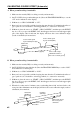
[READ THIS FIRST!!] IMPORTANT NOTICE ON TIDE MEASUREMENTS (In nav-aided mode, tide accuracy depends heavily on gyro accuracy.) SETTING SHIP’S HEADING The CI-35/35H has the nav-aided mode to measure absolute tides even in deep waters where ground tracking is unattainable. To achieve reliable measurements, however, you must supply accurate heading (gyro) information and ship’s position (or speed/course) data to the CI-35/35H.
CALIBRATING COURSE OFFSET (Automatic) A. When ground-tracking is attainable: 1. Make sure the navaid (GPS) is working correctly and accurately. 2. On CI-35/35H, select ground tracking mode. (Press the TRACKING MODE key to see the “GT” mode indication on the display.) 3. In Menu 4, set ‘CRS CAL MODE’ to “GT”. 4. Run your boat at a speed about 10 kts, keeping the same direction. To minimize the effect of gyro speed error, it is desirable to run along parallels (i.e., eastward or westward). 5.
WHY IS GYRO DATA IMPORTANT IN NAV-AIDED MODE? If you consider the difference of tide vector calculations is ground-tracking mode and in nav-aided mode, you will realize how important the gyro (heading) information is. Tide Calculation in Ground-Tracking Mode In ground-tracking mode, the CI-35/35H derives tide information from the following data.
Tide Calculation in Nav-Aided Mode In nav-aided mode, the CI-35/35H derives tide information from the following data. (1) Ship’s speed/course sensed by the external navigator (GPS) (nav speed = pseudo ground speed) (2) Ship’s speed/course based on target layer (water speed) (3) Bearing of ship’s bow (Heading by gyro) Here, nav speed (1) is the ship’s speed vector sensed by the external navigator, and the moving direction is expressed with respect to true north.
CHAPTER 1. GENERAL 1. FEATURES ¡ The functions of CI-35 and CI-35H are same. CI-35H is type approved by MOT (Ministory of Transportation). ¡ Even in deep waters where ground (bottom) reference is not available acoustically, the CI-35/ 35H can provide absolute movements of measuring layers by receiving position (or speed) data from GPS navigator and heading data from gyro compass. It may be used on deep sea fishing boats or on ocean research vessels.
2. PRINCIPLE OF MEASUREMENT When a moving vessel emits an acoustical pulse into the water at an angle, a portion of emitted energy is reflected from the seabed and other microscopic objects in the sound path, such as plankton or air bubbles. The frequency of the received signal is shifted from the transmitted frequency in proportion to relative velocity between the vessel and underwater reflecting objects. This is called Doppler Effect.
Tide Tide is movement of watermass at a particular depth. To know absolute tide (speed on ground), the following two data are required: 1 Ship’s speed and course based on ground 2 Ship’s speed and course based on measuring layer (A) Absolute tide is, then, given as a difference of these two speed vectors.
Tide Differential Tide differential is a relative movement of tides at different depths, layer (A) and layer (B). To calculate tide differential, the following two data are used: 1 Ship’s speed and course based on layer (A) 2 Ship’s speed and course based on layer (B) Tide differential between two layers is, then, given as a difference of these two speed vectors.
3. TIDE, NAV-TIDE & TIDE DIFFERENTIAL Tide (Absolute tide) Absolute tide can be measured in the ground tracking mode. 10 NM (1 hour trip) Start of trip End of trip (Moving at 10 kt on ground) Layer A q (Moving at 3 kt on ground) w :Base of measurement Fixed Assume that the ship and layer A are moving in the same direction, and ship’s speeds based on ground (Vg) and on layer A (Vwa) are measured as; Vg = 10 kt (Ship’s speed based on ground) Vwa = 7 kt (Ship’s speed based on layer A).
Tide Differential Tide differential is a relative movement of tides at different depths. It can be measured in the ground tracking, water tracking and nav-aided modes.
Cd = = = = = C1 - C2 (Vg - Vwa) - (Vg - Vwb) Vwb - Vwa 5-8 -3 (kt) Tide differential based on layer B Speed of layer A viewed from layer B In the water tracking mode, watermass just below the transducer (near-surface layer) is taken as the base of all measurements (virtual ground). Therefore, the ship and tide speeds in the water tracking mode are not absolute but relative to this near-surface layer.
Tide differential calculations in water tracking mode Tide speeds of layer A (C1) and layer B (C2) relative to near-surface layer (Vw) are calculated as follows: D1 = Vw - Vwa (Speed of layer A based on near-surface layer) D2 = Vw - Vwb (Speed of layer B based on near-surface layer) The tide differential (Dd) between layers A and layer B is; Dd = = = = = D2 - D1 (Vw - Vwb) - (Vw - Vwa) Vwa - Vwb 8-5 3 (kt) Tide differential based on layer A Speed of layer B viewed from layer A Dd = = = = = D1 - D2 (Vw -
CHAPTER 2. OPERATION 1. CONTROL PANEL LAYOUT Control panel 1 2 PWR OFF TIDE EFFECT EVENT 4 3 5 6 COURSE PLOT DRIFT 8 7 TIDE DIF HISTORY !0 DEGAUSS button Press this button when picture is distorted or coloration is unbalanced due to magnetization. 9 HU TRIP NU !1 !4 TRACK MODE MANUAL TRACK MENU LAYER ALARM LYR 1 RANGE LYR 2 MENU LYR 3 !2 !5 !3 !6 !8 !7 !9 CONTRAST control Adjusts display color contrast. 4 @0 BRILLIANCE control 6 2 Adjusts display brightness.
2. FUNCTION OF KEYS AND CONTROLS KEY FUNCTION/OPERATION 1 PWR POWER ON : PWR 2 OFF POWER OFF: PWR 3 EVENT + REMARKS OFF Plots event mark “+” at ship’s present position. Event mark moves relatively as ship runs. 16 event marks maximum Functions as “ENTER” key or “EXECUTE” key when menu window is open. 4 TIDE EFFECT Starts tide effect plotting. (A cast mark “ ” is plotted at the start point.) Tide effect plotting shows movements of layers beneath ship’s course track.
KEY !2 MANUAL TRACK FUNCTION/OPERATION REMARKS Enables manual bottom acquisition in ground tracking mode. PREPARATION 1. In MENU 2, set “REF DEPTH” to “OFF.” 2. Select ground tracking mode. MANUAL BOTTOM ACQUISITION 3. Press and hold lights. MANUAL TRACK key until LED lamp on the left of the key (Mode display should change from “GT” to “MAN”.) 4. Turn knob to place manual acquisition cursor ( the bottom echo in the echo level display. 5.
3. OPERATING PROCEDURE SUBJECT/PURPOSE OPERATON (ACTION) 1 Power-on ¡Press 2 Display brilliance adjustment ¡Turn BRILLIANCE control. (CW : Bright, CCW : Dark) 3 Setting measuring depth ¡Press any key. 4 Selecting tracking mode ¡Tap MODE key to select tracking mode. GT/WT/AUTO or GT/NAV/AUTO. *Use ground tracking mode if water depth is shallower than 200m. *Select “T/D” or “NAV-TIDE” in MENU 4 - “WT SPEED” to switch between WT and NAV mode.
CHAPTER 3. DISPLAY 1. DISPLAY SAMPLES Sample 1 Ground Tracking Mode (Ground echo available: GRN) Tide Differential Display (Based on layer 1) Tide Vector Display (North-up mode) Ship’s speed vector: GRN Layer 1 tide vector: YEL Layer 2 tide vector: PPL Layer 1 tide vector: L-BLU Tide dif. vector (1 2): YEL/PPL Tide dif.
2. HOW TO READ THE DISPLAY The display screen of the CI-35/35H is roughly divided into five sections as shown below. What is displayed in each section and how to use it is described on the following pages.
FUNDAMENTAL DATA SECTION SHIP’S SPEED/COURSE Display Ship’s speed and course (true) Course calibration angle (Displayed in NAV mode) Calib. by GT : GRN Calib. by WT : L-BLU Manual calib. : WHT Ship’s heading SPEED COURSE 8.0 DEP 1 25 2 50 3 75 kt W 273° COMPASS 1.2 270.0 17 : 41 : 00 GT DIRECTION TIDE 2.0 3.0 4.0 MODE NE kt SE kt SW TRIP 45° 135° kt 0.00 NM 0 10 20 3° 225° 0.4 kt AVERAGE N 15sec ,,,, ,,,, RANGE 10.0kt 0.5 NE NM DIST 0.
FUNDAMENTAL DATA SECTION TRACKING MODE Display SPEED 8.0 DEP kt W Displays nav data source when NAV mode is selected. ¡GPS: GPS navigator ¡LC : Loran-C navigator ¡DC : Decca navigator ¡DR : Dead-reckoning ¡LA : Loran-A G T 273¡ NE Flows leftward every 3 seconds. Right most segment shows latest status. GT COMPASS 270.0 17 : 41 : 00 TRIP 45¡ 0.
FUNDAMENTAL DATA SECTION ERROR Status display When a source data for calculation and display seems to be abnormal, the following error indication appears on the display. This is to alert the operator not to rely on the related data. No data from the Transceiver Unit. (Red block mark above kt ) No reference data for ship s speed. ( kt in red box) 2 1 SPEED 12.3 DEP 1 5 2 18 3 30 4 COURSE kt SE 135¡ GT N kt NW kt NE kt COMPASS 270.0 17 : 41 : 00 DIRECTION TIDE 1.2 0.8 0.
FUNDAMENTAL DATA SECTION TIDE SPEED/DIRECTION Display (text) Tide speeds/directions of three layers are displayed below the ship’s speed/course. Depending on the tracking mode in use, the meaning of speed/direction changes as follows ` In the ground tracking mode, speed/direction values represent movement of the layer relative to ground. [Ground-based tide = Absolute tide] ` In the water tracking mode, speed/direction values represent movement of the layer relative to near-surface water.
FUNDAMENTAL DATA SECTION Ground Tracking Mode Water Tracking Mode Ship’s movement relative to surface water. Ship’s movement based on ground Direction Measuring depth N Surface Layer (Reference layer) Layer 1 Tide movement of layer 1 Tide movement of layer 1 relative to surface water. Speed Tide movement of layer 2 Layer 2 Tide movement of layer 3 Layer 3 Layer 1 Tide movement of layer 2 relative to surface water. Layer 2 Tide movement of layer 3 relative to surface water.
FUNDAMENTAL DATA SECTION PRESENT TIME Display SPEED COURSE 12.3 DEP 1 15 2 18 3 30 kt TIDE 1.2 0.8 0.5 SE MODE 135° COMPASS GT 270.0 17 : 41 : 00 DIRECTION N kt NW kt NE kt TRIP 0° 320° 45° 0.00 NM 0 10 Present time 10 20 20 3° Trip time (or Trip distance) 0.4 kt AVERAGE N ` Refer to page 4-4 to set date/time of the internal clock. (MENU 2 - “DATE/TIME”) ` It is possible to display time data received from the external navigation equipment, instead of the internal clock.
DRIFT/TIDE DIF SECTION SET & DRIFT Display Press the key to call the set and drift display. DRIFT COMPASS MODE GT 270.0 17 : 41 : 00 1Set angle (Leeway angle) (20¡ port to 20¡ starboard) Deviation of true course from ship s heading. True course (Leeway) TRIP 0.00 NM 0 10 1 N 10 20 20 10¡ 0.4 kt NE 1 2 2 2Drift speed (lateral speed) (9.9 kt port to 9.9 kt starboard) Filled arrow shows drifting direction.
TIDE VECTOR/COURSE PLOT SECTION TIDE VECTOR Display ` Each tide vector can be switched on and off independently by MENU 1 - “LAYER n” setting. (Refer to page 4-2.) ` Tide differential vectors can be switched on and off by MENU 1 - “TIDE DIF DISP” setting. (Refer to page 4-2.) ` Each vector bar indicates “flowing to” own ship direction with the standard factory setting. It is possible to reverse the pointing direction to “flowing from.
TIDE VECTOR/COURSE PLOT SECTION TIDE HISTORY Display The CI-35/35H can hold last 24 tide samples collected at a time interval of 15 sec, 1 min, 5 min, 10 min, 30 min or 1 hour. The tide history presents variation of these tide information with a string of round marks. That is, distance from the graphic center to a mark represents tide speed at the sample time, and the direction from the center to a mark represents tide direction.
TIDE VECTOR/COURSE PLOT SECTION COURSE PLOT Display The course plot display provides ship’s track of last 20 minutes (200 points, one point sampled every 6 seconds). Event positions, stored by the COURCE ` Press the PLOT previous display. EVENT key, are also plotted with “+” marks. key to call course plot display, and press the same key again to restore N Present position NE NW W E Event marks Positions memorized by the SW EVENT key. SE S Ship’s track (200 points max.
TIDE VECTOR/COURSE PLOT SECTION TIDE EFFECT Display The tide effect display is useful for estimating three-dimensional deformation of cast net by the effect of tides at different depths. Notice that display merely shows movements of layers; it does not show true net shape in the water. Assume that you put drifting marks (virtual buoys) on the net at each layer below the vessel at an interval of six seconds.
TIDE VECTOR/COURSE PLOT SECTION Example of tide effect plotting Display (Head-up) b Tide of layer 2 Tide of layer 1 a Buoy track of layer 1 Casting the first virtual buoys at point “a”, vessel made 1/4 of a circle and reached point “b”. d Current Ship's position always at screen center. c Buoy track of layer 2 Assume that each buoy moves on each layer keeping the same speed and direction as at time of measurement.
TIDE VECTOR/COURSE PLOT SECTION Switched on and off in MENU 1 DRIFT Display N Lateral speed (drift) True course (Leeway) NE NW -2 -1 1 2 W SE NW SW -2 -1 1 2 S E SW W Heading line N SE NE S E North-up Head-up HEAD-UP/NORTH-UP Presentation The HU NU key switches between “HEAD-UP” mode and “NORTH-UP” mode. W NW SW S Screen top is always ship’s heading direction (No heading line.
ECHO LEVEL SECTION Display mode selectable in MENU 1 ECHO LEVEL Display Two presentation modes are available for echo level display. ` The “COLOR” mode provides narrow echograms for three directions, presenting echo strengths in color gradation. (Color sounder mode) ` The “GRAPH” mode presents echo strengths of three beams with amplitude varying with depth.
MISCELLANEOUS DATA WATER TEMPERATURE Display (Temperature data from external equipment required.) ` You can switch the temperature display on and off in MENU 1. Time scale (Span: 17 min 30 sec) 15 10 Temperature range 5 20.0 14 15.0 11 TEMP Range width is fixed for 5˚C. It is shifted automatically to bring present temperature near center of the scale. 17.
MISCELLANEOUS DATA MISCELLANEOUS DATA Display (Tide Averaging Time/Total Mileage/Display Range) ` You can change the unit of distance/range to km by an internal DIP switch. (Refer to installation manual.) Speed range Display limit of tide vector bars. AVERAGE 15sec RANGE N DIST ,,,,, ,,,,, Tide data averaging time. Averaging time selectable in MENU1 See page 4-2. 0.5 NM NW NE Distance from center to range cursor (green) 10.0kt 5.
CHAPTER 4. SETTING OPERATING CONDITIONS The CI-35/35H has three menus which you can preset various conditions for measurements and presentations; basic menu range menu and alarm menu. General Rules for Menu Selection Main item selection: Turn knob. ¡CW to move cursor upward ¡CCW to move cursor downward ** MENU 1 ** Jan/15/1997 KNOB ITEM MENU MODE : MENU1 REF TIDE DIF : LAYER1 : 2min MENU2 LAYER2 LYR 3 MENU Mode option selection: Turn Knob.
MENU 1 Jan/15/1997 MENU MODE REF TIDE DIF (Note 1) (Note 2) (Note 4) MENU3 LAYER2 LAYER3 TIDE AVERAGE TIDE HISTORY : 15 sec LAYER1 : ON OFF LAYER2 : ON : ON OFF OFF : ON OFF TIDE DIF DSP DRIFT DSP (Note 3) MENU2 : MENU1 : LAYER1 : 2 min LAYER3 MENU4 2 4 EVENT : DRIFT SPEED : ERASE (0) TEMP DSP : ON OFF ECHO LEV DSP BACKGROUND : COLOR GRAPH : NORMAL 1 MENU 1 3 Knob 1Press KNOB SETUP END : MENU KEY KNOB ITEM * MENU 1 * 5 6 7 OFF 8 9 2 !0 3 Knob key to store
NOTE 1 * Raw tide data is obtainable every 3 sec. Tide averaging time of “1 min” means that averaged data for last one minute is displayed. 1 min After 3 sec. 3 sec. The oldest data is discarded. latest raw data 1 min : Average data for this period is displayed. (Note) Averaging time of “0 min” does not mean immediate display of raw data but average of 15 seconds.
MENU 2 (NOTE 1) * MENU * Jan/15/1997 MENU MODE REF DEPTH KNOB ITEM KNOB SETUP END : MENU KEY MENU3 1 MENU2 BEAM TEST : MENU1 : OFF : OFF SELF CHECK : SINGLE (Note 3) DEMO DATA : OFF CONT1 DP3. 4 (Note 1) TRIP RESET (Note 1) DATE/TIME : RESET : TIME (0.
NOTE 1 Menu items shown in red are protected (or locked) to prevent accidental change of setting. To change the setting of a protected item, follow the procedure below. 1. Place the vertical cursor on the item by using The following message appears. MENU SELECT IS LOCKED knob, and then turn knob clockwise by one step. SET TO UNLOCK UNLOCKED NO YES PRESS EVENT KEY TO ENTER 2. Turn knob clockwise by one step to select “YES”, and then press the 3.
MENU 3 (NOTE 1) * MENU 3 * Jan/15/1997 MENU MODE SHIP SPD AVR KNOB SETUP END : MENU KEY KNOB ITEM MENU3 1 DRAFT : MENU1 : 15sec : 0.0 m WT SPD DEPTH : 2.0 m 4 (Note 2) HEEL ANGLE : 0.0 ° 5 (Note 3) TRIM ANGLE : 0.0 ° : 0.0 % 6 7 : 0.0 % 8 9 !0 GT SPD CALIB MENU2 MENU4 2 3 (Note 4) WT SPD CALIB BEARNG CALIB (Note 6) COURSE CALIB : 0.0 ° : 0.0 ° (GT 0. 0 ° ) (NAV 0. 0 ° ) EXT KP1 DIST : 0.0 m !1 EXT KP2 DIST BTM TIDE TRK : 0.
NOTE 1 NOTE 4 All the items in MENU 3, except “MENU MODE”, appear in red to show that they protected (or “LOCKED”) items. Enter minus value if transducer’s fore-aft axis is oriented to port side of ship’s bow. BEARING CALIB Bow +θ To unlock an item; 1. First, place the vertical cursor on the desired item by knob, and then rotate knob clockwise by one step. The following appears on the display. Transducer MENU SELECT LOCKED UNLOCKED SET TO UNLOCK NO YES PRESS EVENT KEY TO ENTER 2.
MENU 4 * MENU 4 * KNOB ITEM (Note 1) Jan/15/1997 MENU MODE TIME DATA (Note 2) WT SPEED : MENU1 : INT : T/D (Note 3) NAV FORMAT : CIF NMEA (Note 4) NAV AID : GPS LORAN-C (Note 5) NAV DATA : LORAN-A : L/L ALL SPD (Note 6) TIME INT CRS CAL MODE (Note 7) (Note 8) MENU2 MENU4 2 3 4 DECCA 5 DR 6 7 : 1min CRS CAL EXEC : GT : START TIDE OUT INT : 15sec MENU MENU3 1 EXT NAV-TIDE NAV Knob 1Press KNOB SETUP END : MENU KEY 8 MAN 9 !0 Knob key to store (validate) the settings
NOTE 1 TIME DATA “INT”: Displays date/time of internal clock in CI35/35H. Time setting must be done manually in MENU 2-DATE/TIME. Time increments in every one second. NOTE 5 NAV DATA Selects sourse data for pseudo ground tracking speed. “L/L”: Calculates speed/course internally from position data change. (Averaging time interval can be set in TIME INT.) “EXT”: Displays date/time received from external navigator.
2. RANGE SET MENU 2 Distance range For course plot display RANGE 2.0kt 5.0 NM 1 Speed range For speed vector graph 3 Depth range For echo level display 4 Color gradation range For echo level display in color mode 100m 1. To change one of the above ranges, call the RANGE SET menu by pressing the KNOB ITEM *RANGE SET* SPEED RANGE DIST RANGE ECHO DEPTH (Note 1) ECHO SHIFT KNOB SETUP END : RANGE : 10.0 kt : 1.
3. ALARM SET MENU The ALARM menu permits selection of alarm sources and alarm parameters. ALARM FOR TIDE/TIDE DIFFERENTIAL/SHIP’S MOVEMENT This alarm is for alerting you to change in speed and direction of tide/tide dif./ship’s movement. : Alarm range not set. (factory default) : Alarm range (zone) is preset, but alarm function is inactive. : Alarm function is active. : Audible alarm is disabled. (Speaker OFF) : Audible alarm is enabled.
ALARM setting procedure 1. Call “ALARM SET” menu by pressing the 2. By the ALARM key. knob, place the vertical cursor an the desired item; then select an option item by the knob. 3. Press the EVENT key. The subsequent action depends on the location of the horizontal cursor. 1) When the horizontal cursor is on a speaker mark, the audible alarm OFF “ ” or ON “ EVENT key functions to turn the ”. Note that the audible alarm sounds for the items with a filled star mark “ ” beside them.
3) When the horizontal cursor is on an item which has the filled star mark “ following sub-menu appears. ALARM/ALARM ZONE SETTING SELECT : SET ZONE ”, beside it, the KNOB SETUP STOP ALM PRESS EVENT KEY TO ENTER To make alarm setting valid; 1 Place the horizontal cursor on “SET ZONE” by alarm zone setting display appears. EX. Selected “1ST LAYER” - “DIR knob, and press the EVENT key. The ” MAX MIN MIN SET 1. 2kt MAX 280° LYR1 SPD MIN 0.5kt MAX 1.
Alarm Priority Alarm priority is in the order as listed the Alarm menu. ALARM SET 1ST LAYER 2ND LAYER : : SHIP SPEED TRIP Highest priority Lowest priority If multiple alarm conditions are violated, alarm having the highest priority is presented as a visual alarm at the bottom of the display. There is no priority for the audible alarm; the alarm is released whenever an alarm parameter is violated.
Turn knob to set a distance-run, and then hit the EVENT key. A filled star mark “ ” appears aside “DIST” to show the distance alarm setting valid. To start counting distance, press the TRIP key. Note that the alarm distance counting is perfomed internally but not shown on the display. When the preset alarm distance is reached, time-elapsed display becomes red and the counting is stopped. If the audible alarm is enabled (“ ”), it is released. knob for “TIME B.
Example A. Trip distance : 1 NM Ship’s Movement Trip Time display Trip 00 : 05 : 40 Trip time (time-elapsed) to run 1 nm (Indication turns red and freezes.) 1 nm (Alarm limit) Trip 00 : 00 : 00 TRIP key pressed here. Example B. Trip time : 1 hour Ship’s Movement Trip Distance display Trip 012NM Distance-run taking 1 hour (Indication turns red and freezes.) 1 hour (Alarm limit) Trip 000NM TRIP 4-16 key pressed here.
CHAPTER 5. TROUBLESHOOTING 1. SELF-CHECK The CI-35/35H has a self-test facility for general diagnosis of its major circuits. If an unusual symptom is encountered during operation of the equipment, perform the self-check. If the self check reveals equipment fault, shown by the error code, report the results to the service technician when calling for service. (The user should not attempt further check inside the equipment.) WARNING Do not open the cover of the equipment.
3. Place the item cursor on “SELF CHECK” by the knob, and then press the this item is protected (locked), the following alert appears. MENU SELECT IS LOCKED EVENT key. As SET TO UNLOCK UNLOCKED NO YES PRESS EVENT KEY TO ENTER 4. Select ‘YES’ by the knob and press the green to show the item is unlocked. EVENT key. The color of “SELF CHECK” turns 5. Select a check option, SINGLE, CONTI, PANEL or ECHO by the EVENT key, and then press the key to start the self check.
PANEL The PANEL test checks the front panel keys and controls for proper operation. and Press and release each key to see if it is making (1) and breaking (0) correctly. Also, turn knobs to see if the step count changes from 0 to 63. (CW: count up, CCW: count down) To terminate the PANEL test press the MENU key.
2. ERROR INDICATION If the unit detects abnormal operation in the transceiver unit it displays a (blinking) message and a three-digit error code and releases the audible alarm. (Error indication will not interrupt the operation of the equipment.) The error codes and the corresponding status are tabulated below. If multiple items are in error; only the latest error code appears. ERROR CODE 5-4 ERROR STATUS (CHECK ITEM) 000 Abnormal main’s input voltage.
3. Internal Battery A battery fitted inside the display unit preserves data when the equipment is turned off, and its is life is about five years. When its voltage is low no clock may display, etc. Contact your dealer to request replacement of the battery. Parts Name Type Code No.
This page is intentionally left blank.
SPECIFICATIONS 1. MEASURING RANGE 1) SHIP'S SPEED/COURSE Speed: [Fore-aft] [Port-stbd] -10.0kts to +30.0kts -9.9kts to +9.9kts Direction: All directions in one degree steps (0° to 359°) (relative and true bearing) Speed Measurement Depth (Ground tracking mode): 3 m to 500 m beneath the keel (depending on sea condition) (Water tracking mode): 2 m to 25.
2) TEXT DISPLAY ITEM (in table form) Ship's real speed: xx.x(kt) Ship's course: xxx(°) or 32-point notation Tide speed: x.x(kt) (for 3 layers) Tide direction: xxx (°) or 32-point notation (for 3 layers) Depth of tide layer: xxx (m) (for 3 layers) Total mileage: xxxxx. xxx (nm) Present time: xx (h) xx (m) xx (s) Ship's heading: xxx. x (°) (external data) Optional text display (display on/off switchable) Tide differential speed: x.
4. ACCURACY 1) SHIP SPEED ±1 % or ± 0.1 kt 2) TIDE SPEED ±2 % or ± 0.2 kt 3) DIRECTION ±3.5 °(depending on sea condition) 5. TRACKING SPEED 1) SHIP SPEED Less than 40 sec. 2) TIDE SPEED Less than 60 sec. 6. SOUNDING FREQUENCY 130kHz approx. 7. DATA INPUT 1) HEADING DATA Clocked-serial (AD100) ..................................................1ch 2) KEYING PULSE (for interference rejection) Current loop signal ...............................
4) ANALOG SHIP SPEED Current signal for Analog Display. -3.33mA to 10.0mA/-10kt to 30kt (Maximum load 400 ohms) 5) TRUE BEARING DATA Clocked-serial (Furuno AD-100 format) ........................1ch 9. MISCELLANEOUS FUNCTIONS Self-check function, Simple demonstration function 10. NAV-AIDED TIDE MEASUREMENT Even where ground tracking is unattainable, absolute tide movements (tide on ground) can be calculated by applying accurate position and heading data to CI-35/35H.
14. DISTRIBUTION BOX DS-370 1) Input Signal (TTL level) Digital speed signal Log signal (400p/nm) Alarm signal Power on/off signal 2) Output Signal The following output boards are selective. (7 boards max.) (1) OTX board Serial Signal for DS-350/351 Digital Indicator (2) ODD board BCD serial signal for MF11D (LCD spec. only),MF-22D, DS-720/DS-370/DS-377 digital display. (3) OAD board Analog current signal for Analog Display. (1 port /1 board), -2.5mA to 10.0mA/-10kt to 40kt or -3.33mA to 10.