DOPPLER SONAR CURRENT INDICATOR CI-80
C Yo u r L o c a l A g e n t / D e a l e r 9-52, Ashihara-cho, Nishinomiya, Japan Te l e p h o n e : Te l e f a x : 0 7 9 8 - 6 5 - 2 111 0798-65-4200 All rights reserved. Printed in Japan PUB. No. OME-72390 (DAMI) CI-80 FIRST EDITION F : : FEB. 1995 JAN.
SAFETY INSTRUCTIONS WARNING ELECTRICAL SHOCK HAZARD WARNING Keep heater away from equipment. Do not open the equipment. Only qualified personnel should work inside the equipment. Immediately turn off the power at the switchboard if water leaks into the equipment or something is dropped in the equipment. Continued use of the equipment can cause fire or electrical shock. Contact a FURUNO agent for service. Do not disassemble or modify the equipment. Fire, electrical shock or serious injury can result.
Table of Contents PRINCIPLE OF MEASUREMENT................................................................................ 1 PRINCIPLE OF MEASUREMENT, FEATURES.................................................................................. 1 TIDE, NAV-TIDE & TIDE DIFFERENTIAL .......................................................................................... 4 IMPORTANT NOTICE ON TIDE MEASUREMENTS.......................................................................... 8 Features .................
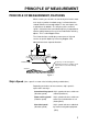
PRINCIPLE OF MEASUREMENT PRINCIPLE OF MEASUREMENT, FEATURES When a moving vessel emits an acoustical pulse into the water at an angle, a portion of emitted energy is reflected from the seabed and other microscopic objects in the sound path, such as plankton or air bubbles. The frequency of the received signal is shifted from the transmitted frequency in proportion to relative velocity between the vessel and underwater reflecting objects. This is called Doppler Effect.
GPS satellites Nav-aided speed (Pseudo ground tracking speed) Water tracking speed Near-surface layer :Base of measurement Ground tracking speed Fixed Figure 2 Tide Tide is movement of watermass at a particular depth. To know absolute tide (speed on ground), the following two data are required: 1 Ship’s speed and course based on ground 2 Ship’s speed and course based on measuring layer (A) Absolute tide is, then, given as a difference of these two speed vectors.
Nav Tide Nav-Tide is an absolute movement of watermass at a particular depth, taking speed information from the external navigator (GPS) as a pseudo ground tracking speed. To calculate Nav-tide, the following two data are required: 1 Ship’s speed and course obtained by external navigation equipment (GPS) 2 Ship’s speed and course based on measuring layer (A) Nav-tide is, then, given as a difference of these two speed vectors.
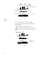
Tide Difference = 1 - 2 (Movement of layer B based on layer A) or = 2 - 1 (Movement of layer A based on layer B) 1 Layer (A) 2 Layer (B) :Base of measurement Figure 5 TIDE, NAV-TIDE & TIDE DIFFERENTIAL Tide (Absolute tide) Absolute tide can be measured in the ground tracking mode.
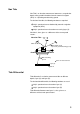
Speed of layer A based on ground (C1) can be calculated as follows: C1 = Vg – Vwa = 10 – 7 = 3 (kt) Nav-Tide (Absolute tide) Absolute tide can be measured in the nav-aided mode. Nav-aided ship’s speed (Vn) is equivalent to ship’s ground tracking speed in the ideal conditions. That is, the nav-tide can be calculated by simply replacing Vg with Vn in the above equation. Tide Differential Tide differential is a relative movement of tides at different depths.
Assuming that the ship, layer A and layer B are moving in the same direction, and ship’s speeds based on layer A (Vwa) and on layer B (Vwb) are measured as; Vwa = 8 kt (Ship’s speed based on layer A) Vwb = 5 kt (Ship’s speed based on layer B) Tide differential calculations in ground tracking mode As an absolute ship’s speed (Vg) is available in the ground tracking mode, tide speeds of layer A (C1) and layer B (C2) based on ground are calculated as follows: C1 = Vg - Vwa (Speed of layer A based on ground)
10 NM (1 hour trip) Start of trip Nearsurface layer 1 2 Layer A End of trip 3 :Base of measurement Layer B Assume that the ship and all measuring layers are moving in the same direction, but at different speeds.
[READ THIS FIRST!!] IMPORTANT NOTICE ON TIDE MEASUREMENTS (In the nav-aided mode, tide accuracy depends heavily on gyro accuracy.) SETTING SHIP’S HEADING The CI-80 has the nav-aided mode to measure absolute tides even in deep waters where ground tracking is unattainable. To achieve reliable measurements, however, you must supply accurate heading (gyro) information and ship’s position (or speed/course) data to the CI-80.
10 0 10 10 20 20 0 10 20 20 1° -3° 0.2 kt 0.
Features The CI-80 mainly consists of three units: a display unit, a transceiver unit, and a transducer, each compact enough to fit on small boats. The main features of the CI-80 are; • • • • • • • • • 10 Even in deep waters where ground (bottom) reference is not available acoustically, the CI-80 can provide absolute movements of measuring layers by receiving position (or speed) data from GPS navigator and heading data from gyro compass.
SYSTEM OVERVIEW Control Description Display unit (CI-800) Figure 11 Display unit Transceiver unit (CI-810) Figure 12 Transceiver unit 11
Table 1 Control description Control Description Turns the system on/off. ON OFF Adjusts brilliance of display. Setting can be locked by pushing in control. 0 10 BRLL Alternately selects echo display and course plot display. DISP MODE MODE Selects tracking mode among ground tracking, water tracking, nav aided and automatic selection. (G) (W) (A) (G) (N) (A) Select "T/D" or "NAV" from the item WATER SPEED on the SYSTEM menu. Opens/closes the menu. MENU Select menu.
How to Read the Displays The CI-80 has two display modes: echo display and course plot display. A display may be selected with the DISP MODE key.
When speed or depth data appears in red… Speed or depth data containing error appears in red. Ships speed Cannot find reference echo in respective tracking mode. Tide speed Cannot find echo in given layer. Set depth Depth set is invalid. In ground tracking mode, depth should be shallower than 7 m, or in the water tracking mode no more 3/4 of seabed depth. Measured speed When measured speed (tide or ship's) is unreliable.
NOTE 2: Ship's speed and course displays are update every three seconds, in the default setting. They can be updated every second. For details, consult your dealer.
MAIN MENU DESCRIPTION Most major functions of the CI-80 are carried out through an easy-to-follow menu system. The menu system consists of two main groups of menus: main (operation) and system (testing, calibration). This chapter covers the main menu. For complete menu tree, see page 36. Basic Menu Operation Most major functions of the CI-80 are carried out through an easy-to-follow menu system. Two general types of menus are used: main (operation) and system (testing).
ECHO Menu Sets up the echo display. SPEED RANGE: Sets length of tide speed vector between 0.1 and 15.0 knots, in resolution of 0.1 knots. ECHO DEPTH RANGE: Sets echo depth range. Depth can be set either manually between 50 and 300 meters in resolution of 50 meters or automatically. In AUTO, seabed depth is automatically selected as depth range. ECHO LEVEL SHIFT: Sets echo intensity level, between 1 and 100 in resolution of 1. The higher the figure the stronger the echo level.
MARK Menu This menu sets measuring conditions for tide vector and target point mark. PRESET REFERENCE VALUE: Sets the effect of tide on the target point mark. The higher the figure, the greater the effect of tide. TIDE HISTORY: Sets tide vector plotting interval, among 0 (turns off tide vector display), 15 sec. (1/4 min.), 1 min., 5 min., 10 min., 30 min., and 60 min.
OPERATION Basic Operating Procedure Turning on the system 1. Turn on the transceiver unit. 2. Turn on the display unit. 3. Adjust brilliance of display. The display unit conducts a check of the system, displaying the results about 40 seconds after turning on the power. Figure 20 Display unit and transceiver unit Selecting operating mode Press the MODE key to select operating mode among water tracking, ground tracking, or automatic selection. Selected mode appears at top right corner on the display.
Ground Tracking Mode: Shows absolute ship and tide movements based on ground. (Bottom echo required.) Water Tracking Mode: Shows movements of ship and tide relative to near-surface water. Nav-aided Mode: Shows ship’s movement measured by the external navigation equipment, and the tide movements based on the nav speed data. Auto Tracking Mode: Uses ground tracking mode when bottom echo is available. Switches to water tracking mode (or nav-aided mode) when bottom echo is lost.
Setting tide differential layer 1. On the DEP menu, press DIFFERENCE. 2. Press / / to select REF TIDE to set layer. Figure 22 How to set tide differential Turning off the power Press the power switch on the display unit.
Setting Tide Measuring Depths on the Echo Display Earlier you learned how to set tide measuring depths on the DEP menu. Measuring depths can also be set directly on the echo display. Selecting a layer, setting depth 1. On the echo display, press / to select layer desired. Selected layer’s depth indication changes from white to orange. Figure 23 Echo display 2. Press / to set depth. “DEPTH SETTING” appears while setting depth. 3. Press white. 22 to finish.
Setting up the Echo Display Setting tide speed vector range 1. Press the MENU key. 2. Press ◄ / ► to select the ECHO menu. 3. Press / RANGE. to select SPEED 4. Press / to set speed. (Default setting: 1.0 knot) Figure 24 ECHO menu Setting echo depth range 1. Press / to select ECHO DEPTH RANGE. 2. Press / to set depth. (Default setting: 100 meters) 1. Press / to select ECHO LEVEL SHIFT. 2. Press / to set echo intensity.
Setting up the Course Plot Display The course plot display mainly plots ship’s track. It can be displayed by pressing the DISP MODE key. Figure 25 Sample course plot display, TRK menu Setting the plot range 1. Press the MENU key. 2. Press ◄ / ► to select the TRK menu. 3. Press / to select PLOT RANGE. 4. Press / to set plot range. 1. Press / to PLOT MODE. 2. Press / to select HU (Head-up) or NU (North-up). Setting plot orientation Setting tide vector plotting interval 1.
Marks The CI-80 has two types of marks which can be inscribed on the display: event mark and target point mark. Figure 27 Appearance of event mark and target point mark Event mark The EVENT key inscribes present position on the display. It is useful for marking important locations, etc. 25 event marks may be entered. When the event mark memory is full the oldest event mark is erased to make room for the latest. Target point mark The TARGET POINT key inscribes a target point mark on the display.
Erasing marks 1. Press the CURSOR ON/OFF key. 2. Operate the four arrow keys to place cursor on mark to erase. 3. Press the EVENT key (or TARGET POINT key). Figure 28 How to erase marks Calculating Trip Distance Press the TRIP key to start calculation of trip distance from present position. The trip distance indication is automatically reset to zero.
Displaying the CALB menu MODE 1. Press ◄ / ► to select the CALB menu. CALB GT SPD CALIB 2. Press / to select menu item. 0.0 3. Press / to set offset. % [-12.8~12.7] WT SPD CALIB 0.0 % [-12.8~12.7] DRAFT LEVEL 0.0 m ° ° Raise setting when ground tracking speed is slower than ship’s speed. WT SPD CALIB: Raise setting when water tracking speed is slower than ship’s speed. DRAFT LEVEL: Enter depth of transducer from sea surface. [-12.8~12.7] COURSE CALIB 0.0 GT SPD CALIB: [0.0~50.
MODE CALB SELF TEST OFF SYS ECHO PNL DEMONSTRATION OFF ON WATER SPEED T/D NAV NAV DATA SPD *1 *1 L/L *1: Shown when tide processor is active. Figure 31 MODE menu Nav Data Setting 1. Press the DISP MODE key to display the echo display. 2. While pressing and holding down the TRIP key press the MENU key. 3. Press ◄ / ► to select MODE. 4. Press or to select NAV DATA. 5. Press or to select L/L or SPD. “L/L”: Calculates speed internally from position data change.
MAINTENANCE & TROUBLESHOOTING Preventive Maintenance Regular checks • • • • Regular maintenance is important for continued performance. Check the following on a monthly basis. Check that all connectors and cables are securely tightened. Check grounding systems of units for corrosion. Also regularly measure voltage to confirm that it is within prescribed rating. Cleaning of units Display unit/ transceiver unit Accumulated dirt can be wiped off with a soft cloth.
Troubleshooting The troubleshooting table which follows provides simple troubleshooting procedures which the user may use to restore normal operation. If normal operation cannot be restored, do not attempt to check inside any unit. Any repair is best left to a qualified technician. Table 2 Troubleshooting table If… Then… power is on but nothing appears on the display • adjust BRILL control. • check power cable. • check for loosened power connector. • check for blown fuse.
Self Tests, Demonstration Display The CI-80 has four self tests and a demonstration display which check the system for proper operation. Display the system menu 1. Press the DISP MODE key to select the echo display. 2. While pressing and holding down the TRIP key, press the MENU key. Conducting self tests MODE 1. Press ◄ / ► to select the MODE menu. CALB SELF TEST 2. Press / to select SELF TEST OFF SYS ECHO PNL 3. Press / to select test.
Starting the demonstration display MODE CALB OFF SYS ECHO PNL The demonstration display checks the controls on the display unit and conducts a loopback test between the display unit and the transceiver unit. DEMONSTRATION 1. Press / OFF 2. Press to select ON. SELF TEST ON WATER SPEED T/D SPD *1 3. Press the EVENT key. *1 The echo display appears and the demonstration begins. "DEMO DATA OUTPUTTING” appears while the demonstration display is on.
Self Test Results System test The system test check results appear at each power on or whenever the system check is conducted though the self test. SYSTEM CHECK ---------CI-800--------IP VOL IP DSW 66503001** “00 00” IP MEM IP MEM 1 2 3 4 5 6 OK 789 ICP Board ROM prog. no. IPU Board’s DIP switch setting in hexadecimal notation ICP Board memory test ---------CI-810--------CP VOL CP VOL CP MEM CP DSW 66503101** JCPA Board ROM prog no.
Error display “OK” appears for normal memory IC test. For fault NG (No Good) and asterisk (*) appear next to ROM/RAM number.
Echo test Checking echo display intensity Press the right and left arrow keys. The SHIFT indication should change with key operation, between 0 and 100. Checking echo display range Press the up and down arrow keys. The echo display range should in steps of 50 between 0 and 300. Figure 34 Sample echo test display Panel test Press each key on the control panel one by one. The pressed key’s corresponding “0” on the display should change to “1”.
MENU TREE MAIN MENU SYSTEM MENU DEP LAYER1 LAYER2 LAYER3 REF TIDE DIFFERENCE ECHO SPEED RANGE ECHO DEPTH RANGE ECHO LEVEL SHIFT TRK PLOT RANGE PLOT MODE TRACK DISPLAY MARK PRESET REFERENCE VALUE TIDE HISTORY AVR SHIP SPD AVR TIDE AVERAGE WT SPD DEPTH MODE SELF TEST OFF SYS ECHO PANEL DEMONSTRATION OFF ON WATER SPEED T/D NAV NAV DATA SPD L/L CALIB 36 GT SPD CALIB WT SPD CALIB DRAFT LEVEL BEARING CALIB COURSE CALIB
SPECIFICATIONS OF CI-80 1. General (1) Ground tracking acquirable depth (2) Measurable tide range (3) Measurable tide depth (4) Measurable ship's speed (5) Measurable tide speed (6) Tide differential range (7) Measuring accuracy (8) Number of beams (9) Transmitting frequency (10) Display type 2. Display (1) Common displays (2) Course plot display (3) Echo display (4) Other 3. Input/Output Signal (1) Input signal (2) Output signal 4. (1) (2) 5.