Installation Manual RADAR SENSOR DRS2D/DRS4D/ DRS4A/DRS6A/DRS12A/DRS25A SAFETY INSTRUCTIONS ............................................................................ i SYSTEM CONFIGURATION ....................................................................... ii EQUIPMENT LISTS.................................................................................... iv 1. MOUNTING ............................................................................................ 1 1.1 1.2 1.3 1.
SAFETY INSTRUCTIONS Read these safety instructions before installing the equipment. WARNING Indicates a potentially hazardous situation which, if not avoided, could result in death or serious injury. CAUTION Indicates a potentially hazardous situation which, if not avoided, canresult in minor or moderate injury. WARNING WARNING Do not open the equipment unless totally familiar with electrical circuits and service manual. Only qualified personnel should work inside the equipment.
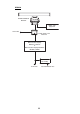
SYSTEM CONFIGURATION DRS2D/4D/4A/6A/12A RADAR SENSOR DRS2D/DRS4D RADAR SENSOR DRS4A/DRS6A/DRS12A NMEA 2000 Equipment Power Supply Unit*1 PSU-017*2 NMEA 2000 Equipment Power Supply Unit*1 PSU-012 12-24 VDC Multi Function Display BlackBox MFDBB or 12-24 VDC Multi Function Display MFD8/12, TZT9/14 or Multi Function Display BlackBox TZTBB RECTIFIER RU-1746B 12-24 VDC 100/110/220/230 VAC *1: The power supply unit (PSU-012/017) is necessary in the combination of radar sensor and multi function displa
DRS25A RADAR SENSOR DRS25A NMEA 2000 Equipment 12-24 VDC Power Supply Unit PSU-013 Multi Function Display MFD8/12, TZT9/14 or Multi Function Display BlackBox MFDBB, TZTBB RECTIFIER RU-1746B 12-24 VDC 100/110/220/230 VAC iii
EQUIPMENT LISTS Standard supply Name Radar Sensor Type XN10A-RSB-118-092 Code No.
Optional supply Name Type Code No.
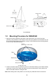
1. MOUNTING NOTICE Do not apply paint, anti-corrosive sealant or contact spray to coating or plastic parts of the equipment. Those items contain organic solvents that can damage coating and plastic parts, especially plastic connectors. 1.1 Mounting Considerations • The radar sensor is generally installed either on top of the wheelhouse or on the radar mast on a suitable platform. Locate the radar sensor where there is a good all-round view. Any obstruction will cause shadow and blind sectors.
Radar sensor Radar sensor Radar sensor Radar sensor For DRS2D/4D 1.2 Mounting Procedure for DRS2D/4D 1. Remove mounting hardware at the bottom of the radar sensor, four each of hex bolts (M10x20), spring washers and flat washers. Save the spring washers and flat washers to use them to fix the radome base to the platform, at step 3. If the thickness of the mounting platform is 5 mm or less, also save the bolts.
3. Use the hex bolts*, flat washers and spring washers removed at step 1, and fasten the radome base to the platform. The torque should be between 19.6-24.5Nzm. *If the thickness of the platform is 6-10 mm, use M10x25 bolts (supplied). For thicker platform, use locally supplied bolts. Transceiver module L Flat washer Spring washer Antenna base assy.
5. Coat the hex bolts (4 pcs.) with silicone sealant. Fasten the antenna radiator to the radiator bracket with the hex bolts, flat washers and spring washers supplied with the radiator Then, apply silicone sealant around the junction part between the radiator and bracket. 6. Apply silicone sealant to holes to prevent water ingress. Antenna radiator Radiator bracket, bottom view O-ring Radiator bracket Flat washer Spring washer Hex bolt (M8 x 30) 1.3.2 Coat threaded holes with silicone sealant.
2. Lay the radar sensor on the mounting platform, orienting it as shown below. (The hinges must face toward the stern.) BOW STERN Hinge CAUTION Do not lift the radar sensor by the radiator; lift it by the housing. The radiator may be damaged. 3. Insert four hex bolts (M12 x 60, supplied) and seal washers (φ30, supplied) from the top of the housing, as shown below. Hex. bolt Seal washer (Face projecting part down.
4. Pass flat washers (M12, supplied), spring washers (M12, supplied) and nuts (M12, supplied) onto hex. bolts. Fasten by tightening nuts. Do not fasten by tightening the hex. bolts; seal washers may be damaged. Seal washer Antenna unit Mounting platform Silicone sealant Rubber mat Flat washer 5. Coat flat washers, spring washers, nuts and exposed parts of bolts with anticorrosive sealant. 6.
Using inside fixing holes of the sensor housing If this radar is replacing a FURUNO radar whose mounting dimensions are the same as this one (140 x 150 mm), it may be possible to use its mounting platform. This method requires removal of the RF unit from the radar sensor to access inside fixing holes. Use hex bolts, flat washers, spring washers and nuts (local supply) to mount the radar sensor. 1. Unfasten four bolts from the cover to open the radar sensor. 2. Unplug the PCS connector from RF unit. 3.
1.4 Mounting of Power Supply Unit 1.4.1 PSU-013 (for DRS25A)/PSU-012 (Option) For combinations shown below, the optional power supply unit PSU-012 or PSU-017 is necessary.
Mounting When selecting a location, keep in mind the following points. Fix the power supply unit on the desktop or bulkhead with four self-tapping screws (4x20, supplied). • Location is dry, well ventilated. • Make sufficient maintenance space. • Installed within 2, 5 or 10 m (2 and 10 m: optional supply) from the multi function display. Self-tapping screw (4x20, 4 pcs.) Note: When you install the unit on the bulkhead, fix the unit with the following direction.
1.4.2 PSU-017 (option) A power supply unit is required when you connect a radar sensor. The PSU-017 is available in the combination of DRS2D/4D and TZT9/14/BB. Use the PSU-012 or PSU-013 in all other combinations. LED for the operation check: Lights in green when the unit outputs 48 VDC. Power cable (5 m): The power cable is preattached to the unit. Note: When the fuse in this unit blows, the LED does not light. At this time, the PSU-017 can not output 48 VDC, but high voltage is still present inside.
2. WIRING The MFDBB, MFD8, MFD12, PSU-012 or PSU-017 connects to the radar sensor with the two-way cable MOD-ASW0001 (MOD-ASW0002 for DRS25A). In order to minimize the chance of picking up electrical interference, avoid where possible routing the two-way cable near other onboard electrical equipment. After passing the cable through the hole in the radar sensor, apply sealing compound around the hole for waterproofing.
Wiring for DRS2D/4D/4A/6A/12A with PSU-012 Radar Sensor DRS2D/DRS4D Radar Sensor DRS4A/DRS6A/DRS12A NMEA2000 cable M12-05BFFM (ø6) or CB-05BFFM (ø10) Two-way cable MOD-ASW0001 (10/15/20/30 m) NMEA2000 Equipment NMEA2000 cable M12-05BFFM (ø6) or CB-05BFFM (ø10) NMEA2000 Equipment (Power) (LAN) Power Supply Unit PSU-012 : Standard Supply 12-24 VDC : Optional Supply Power cable VL3P-VV-S2X2C-AA050 (supplied with PSU-012) LAN cable MOD-WPAS0001-030+ 3 m: supplied with MFD8/12/BB, TZT9/14/BB To shi
Wiring for DRS25A RADAR SENSOR DRS25A NMEA2000 cable M12-05BFFM (ø6) or CB-05BFFM (ø10) Two-way cable MOD-ASW0002 cable (10/15/20/30 m) NMEA2000 Equipment (POWER) (LAN) Power cable VL3P-VV-S2X2C-AA050 (Supplied with PSU-013) Power Supply Unit PSU-013 12-24 VDC Ground wire (Local supply, IV-2sq) To ship's ground LAN cable MOD-2072-050 To Multi Function Display BlackBox MFDBB/TZTBB or Multi Function Display MFD8/12, TZT9/14 13 : Standard Supply : Optional Supply : Local Supply
How to terminate of NMEA2000 connection When connecting the radar sensor and an NMEA2000 equipment using the optional cable M1205BFFM (φ6) or CB-05BFFM (φ10), attach the terminator (supplied as installation materials) to the NMEA connector in the radar sensor. 1. Twist the lead wire of the resistor assembly to the cable M12-05BFFM (φ6) or CB-05BFFM (φ10), and solder them as below. Resistor assembly (120 OHM-1007#24-L50) White Twisting and soldering Blue NMEA2000 cable 2.
2.1 Wiring inside DRS2D/4D Two-way cable connection 1. Unfasten three screws at the bottom of the mounting base to remove the fixing plate for the gasket. Fixing plate (for gasket) 2. Remove the gasket, and pass the two-way cable MOD-ASW0001. 3. Fasten the shield of the cable (power) with the cable clamp in the radar sensor, and connect the connector of cable (power) to the power terminal. 4. Connect the RJ-45 connector of the cable (LAN) to the LAN terminal in the radar sensor.
6. Slide the gasket on cables so that the amount of cable above the gasket is lower than the RF chassis. This height should be lower than the RF unit when installed to the bottom of the sensor. Gasket Cable RF unit Gasket Note: If the two-way cable touches the platform near the mounting base, wind vinyl tape around the cable at the point where it is bent. 7.
5 15 Shield CB-05BFFM cable 370 Wind vinyl tape. (supplied) Fasten the cable tie (supplied) within 15 mm from the end of vinyl sheath. CB-05BFFM cable 20 65 15 (Area fastened with the cable clamp) Fabrication of CB-05BFFM cable 3. Insert wires of cable M12-05BFFM (φ6) or CB-05BFFM (φ10) to the NMEA connector inside the radar sensor, consulting the label on the connector for location. As for shield, use the cable clamp shown below.
4. Push LAN and POWER cables of the two-way cable and cable M12-05BFFM (φ6) or CB05BFFM (φ10) into the slits of the gasket inside the mounting base. Depending on the NMEA2000 cable used, replace the gasket as shown below. Cable type Gasket M12-05BFFM (φ6) CB-05BFFM (φ10) Use the gasket supplied in the plastic bag inside the radar sensor. Use the optional gasket. (Type: OP03-203, Code No.: 001-025-290) Note: The ends of the gasket are different. Larger end should be up) Large Up Small 5.
2.2 Wiring inside DRS4A/6A/12A/25A Two-way cable connection If you have no NMEA2000 equipment to connect, use the MOD-ASW0001 cable (standard supply). 1. Open the radar sensor cover by loosening four bolts, and fix the stay for safety purpose. 2. Unfasten four bolts to detach the plate, gasket, washer and lid. Discard the lid at the bottom of the hole for the gasket. Plate Gasket Washer Lid Stay 3. Pass the two-way cable MOD-ASW0001 (MOD-ASW0002 for DRS25A) through the bottom of the chassis and washer.
5. Attach the LAN cable of the two-way cable to the LAN terminal in the radar sensor. Fix the power cable at the foil part with this cable clamp. Power cable White Power terminal Black LAN cable RF unit LAN terminal DRS4A/6A/12A Fix the power cable at the copper foil part with this cable clamp. Gasket LAN cable White Power terminal Blue Red Power cable Black LAN terminal DRS25A 6.
7. Slide the gasket on cables so that the amount of cable above the gasket is lower than the RF chassis. This height should be lower than the RF unit when installed to the bottom of the sensor. Cable RF unit Gasket Gasket Washers 8. Push the gasket and washers into the hole at the bottom of the radar sensor, then fasten four pan head screws to fix the plate to the sensor. 9. Release the stay and close the cover.
the crimp-on lug (pre-attached at the bottom of the chassis) to the drain wire, and fasten it with the screw shown below. A NMEA connector view NMEA connector Crimp-on lug A Drain wire Fasten the drain wire with this screw. NMEA cable RF unit 5. Depending on the NMEA2000 used, replace the gasket as shown below. DRS4A/6A/12A Cable type Gasket M12-05BFFM (φ6) CB-05BFFM (φ10) Use the gasket supplied in the plastic bag inside the radar sensor. Use the optional gasket. (Type: OP03-205, Code No.
2.3 Wiring of Power Supply Unit 2.3.1 Wiring inside power supply unit PSU-013 (for DRS25A) 1. Detach the body cover by hand. 2. Loosen six pan head screws (M3x8) and slide the shield cover upward to remove it. 3. Unfasten four pan head screws (M14x10) to remove two cable clamps. Body cover Shield cover Pan head screws (M4x10, 4 pcs.) Cable clamps Pan head screws (M3x8, 6 pcs.) 4.
2.3.2 Wiring inside power supply unit PSU-012 (Option) 1. Detach the body cover by hand. 2. Loosen six pan head screws (M3x8) and slide the shield cover upward to remove it. 3. Unfasten two pan head screws (M4x12) to remove the cable clamp. Body cover Shield cover Pan head screw (M4x12, 2 pcs.) Cable clamp Pan head screw (M3x8, 6 pcs.) 4. Connect the cable VL3P-VV-S2X2C-AA050 (supplied) to the power connector in the PSU012.
2.3.3 Wiring the power supply unit PSU-017 (option, for DRS2D/4D) Connect the power cable and MOD-ASW0001 cables to appropriate connectors of the power supply unit as shown below. When you connect the power cable to ship’s mains, pass through the disconnecting device (breaker, etc.). MOD-ASW0001 cable Power cable*1 To ship’s mains (12-24 VDC)*2 To radar sensor DRS2D/4D *1: Input voltage range at the edge of the power cable: 10.8 to 31.2 VDC.
3. Confirm that the LED on the board is OFF, and then replace the fuse. Note: DO NOT change the fuse if the LED is ON; this indicates high voltage is present. Fuse F2 (1.5A 125V) Fuse F1 (7A 125V) J1 1: Brown (P48V) 2: Red (DC_N) TB1 1: White (DC_P) 2: Black (DC_N) LED 4. Reattach the base and install the unit. Note: Before fixing the base, make sure the waterproofing gasket is correctly seated in the groove in the chassis.
FURUNO DRS SERIES SPECIFICATIONS OF RADAR SENSOR DRS SERIES 1 1.1 1.2 1.3 1.4 1.5 1.6 1.7 2 2.1 2.2 2.3 2.4 2.5 RADIATOR Antenna type DRS2D/4D Patched waveguide array antenna DRS4A/6A/12A/25A Slotted waveguide array antenna Antenna length DRS2D 19-inch DRS4D 24-inch DRS4A 3.4 ft DRS6A 4 ft DRS12A/25A 4 ft (XN12A), 6 ft (XN13A) Horizontal beam width (3 dB) DRS2D 5.2° DRS4D 4.0° DRS4A 2.3° DRS6A 1.9° DRS12A/25A 1.9° (XN12A), 1.
FURUNO 2.6 Maximum range 2.7 2.8 2.9 Minimum range Range resolution Bearing resolution 2.10 Bearing accuracy 2.11 Range accuracy 3 3.1 3.2 3.3 4 4.1 4.2 4.3 DRS SERIES DRS2D: 24 NM, DRS4D: 36 NM, DRS4A: 48 NM, DRS6A: 64 NM, DSR12A: 72 NM, DRS25A: 96 NM 25 m 20 m DRS2D: 5.2°, DRS4D: 4°, DRS4A: 2.3°, DRS6A: 1.9°, DRS12A/25A: 1.9° (XN12A) or 1.4° (XN13A) ±1° 0.
*': $1.6 5.166'& *'#& ⷺ㩇㩢㩦㩢 㩘㩨㩣㩎 524+0) 9#5*'4 㩔㩨㩒ᐳ㊄ (.#6 9#5*'4 㩚㩀㩨㩁ᐔᐳ㊄ 4'5+5614 #55'/$.; 㩍㨼㩄㨽⚵ຠ ฬޓޓ⒓ 0#/' %1&' 01 / : 575 %1&' 01 / 575 ޓ %1&' 01 / 575 / 575 / 575 %1&' 01 1*/ . 㧲㨁㧾㨁㧺㧻ޓ㧱㧸㧱㧯㨀㧾㧵㧯ޓ㧯㧻ޓ㧚㧘㧸㨀㧰 㧔⇛࿑ߩኸᴺߪޔෳ⠨୯ߢߔ&ޓޕ+/'05+105 +0 &4#9+0) (14 4'('4'0%' 10.
%#$.' #55; 㩃㨺㩖㩨㩣⚵ຠ *':#)10#. *'#& $1.6 ⷺ㩘㩨㩣㩎 (.#6 9#5*'4 㩚㩀㩨㩁ᐔᐳ㊄ ฬޓޓ⒓ 0#/' ⇛ޓޓ࿑ 176.+0' %1&' 01 49 49 %1&' 01 / : 575 %1&' 01 / 575 ဳฬ㧛ⷙᩰ &'5%4+26+105 %2 6;2' ᢙ㊂ 3 6; ↪ㅜ㧛⠨ 4'/#4-5 ); : 㧲㨁㧾㨁㧺㧻ޓ㧱㧸㧱㧯㨀㧾㧵㧯ޓ㧯㧻ޓ㧚㧘㧸㨀㧰 㧔⇛࿑ߩኸᴺߪޔෳ⠨୯ߢߔ&ޓޕ+/'05+105 +0 &4#9+0) (14 4'('4'0%' 10.; 㧕 % / & 691 6;2'5 #0& %1&'5 /#; $' .+56'& (14 #0 +6'/ 6*' .
%#$.' #55; 㩃@㩖㩨㩣⚵ຠ %#$.' #55; 㩃㨺㩖㩨㩣⚵ຠ %#$.' #55; 㩃㨺㩖㩨㩣⚵ຠ %#$.' #55; 㩃㨺㩖㩨㩣⚵ຠ ฬޓޓ⒓ 0#/' &45 # ⇛ޓޓ࿑ 176.+0' %1&' 01 /1& #59 %1&' 01 /1& #59 %1&' 01 /1& #59 %1&' 01 /1& #59 ဳฬ㧛ⷙᩰ &'5%4+26+105 ᢙ㊂ 3 6; ㆬᛯޓ61 $' 5'.'%6 ㆬᛯޓ61 $' 5'.'%6 ㆬᛯޓ61 $' 5'.'%6 ㆬᛯޓ61 $' 5'.
D-1
D-2
D-3
D-4
D-5
D-6
C B A 1 2 3 4 5 6 7 8 1 2 3 E_TD-P E_TD-N E_RD-P NC NC E_RD-N NC NC +48V GND SHIELD 1 2 3 +48V GND SHIELD *3 MJ-A3SPF *3 RJ45 *3 MJ-A3SPF NOTE 1. SHIPYARD SUPPLY. 2. OPTION. 3. CONNECTOR PLUG FITTED AT FACTORY.
C B 1 2 3 4 5 6 7 8 1 2 3 E_TD-P E_TD-N E_RD-P NC NC E_RD-N NC NC +48V GND SHIELD 1 2 3 +48V GND SHIELD NOTE 1. SHIPYARD SUPPLY. 2. OPTION. 3. CONNECTOR PLUG FITTED AT FACTORY. 12-24VDC P P P P P *3 RJ45 クロ BLK VL3P-VVS2x2C,5m シロ WHT RJ45 VVRx2C P 1 2 3 4 5 6 7 8 1 2 3 4 5 6 7 8 パワーサプライユニット *1 1 2 3 1 2 3 4 5 6 7 8 DWG.No. SCALE C3569-C01- E kg Y.NISHIYAMA H.MAKI REF.No. POWER 1 48V-H 2 48V-C NETWORK E_TD-P E_TD-N E_RD-P NC NC E_RD-N NC NC T.
C B A 3 4 5 6 7 8 *3 2 3 4 5 6 7 8 NOTE *1: SHIPYARD SUPPLY. *2: OPTION. *3: CONNECTOR PLUG FITTED AT FACTORY. *4: ATTACH A TERMINATOR. 注記 *1)造船所手配。 *2)オプション。 *3)コネクタは工場にて取付済み。 *4)ターミネータを接続する。 E_TD-N E_RD-P NC NC E_RD-N NC NC RJ45 MFDBB(MPU-001) MFD8/12 E_TD-P 1 P P P P *3 RJ45 1 2 3 4 5 6 7 8 J1 1 (+) 2 3 (-) E_TD-P E_TD-N E_RD-P NC NC E_RD-N NC NC VVRx2C *1 DWG.No. SCALE MASS kg Y.NISHIYAMA H.MAKI T.
C B A 2 3 4 5 6 7 8 12/24VDC P P P P *3 RJ45 NOTE 1. SHIPYARD SUPPLY. 2. OPTION. 3. CONNECTOR PLUG FITTED AT FACTORY.
FURUNO Worldwide Warranty for Pleasure Boats (Except North America) This warranty is valid for products manufactured by Furuno Electric Co. (hereafter FURUNO) and installed on a pleasure boat. Any web based purchases that are imported into other countries by anyone other than a FURUNO certified dealer may not comply with local standards.
FURUNO Warranty for North America FURUNO U.S.A., Limited Warranty provides a twenty-four (24) months LABOR and twenty-four (24) months PARTS warranty on products from the date of installation or purchase by the original owner. Products or components that are represented as being waterproof are guaranteed to be waterproof only for, and within the limits, of the warranty period stated above.
(Elemental Chlorine Free) The paper used in this manual is elemental chlorine free. FURUNO Authorized Distributor/Dealer 9-52, Ashihara-cho, Nishinomiya, 662-8580, JAPAN All rights reserved. Printed in Japan Pub. No. IME-35670-F (REFU) DRS2D/4D/4A-25A A: JAN. 2008 F: FEB.