Installation Manual COLOR LCD SOUNDER FCV-1150 SAFETY INSTRUCTIONS ............................................................................ i SYSTEM CONFIGURATION ...................................................................... iii EQUIPMENT LISTS.................................................................................... iv 1. MOUNTING ............................................................................................ 1 1.1 1.2 1.3 Display Unit ..................................
SAFETY INSTRUCTIONS The operator and installer must read the applicable safety instructions before attempting to install or operate the equipment. WARNING Indicates a potentially hazardous situation which, if not avoided, could result in death or serious injury. CAUTION Indicates a potentially hazardous situation which, if not avoided, can result in minor or moderate injury.
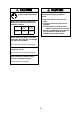
CAUTION CAUTION Ground the equipment to prevent mutual interference. The transducer cable must he handled carefully, following the guidelines below. • Keep fuels and oils away from the cable. • Locate the cable where it will not be damaged. • The cable sheath is made of chlorophrene or polychloride vinyl, which are easily by damaged plastic solvents such as toulene. Locate the cable well away from plastic solvents.
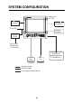
SYSTEM CONFIGURATION Display unit CV-1150 NavNet 3D Navigator 12-24 VDC Satellite compass Rectifier PR-62 100/110/115/ 220/230 VAC 1㱢, 50/60 Hz Temperature sensor T-02MSB, etc. Speed/temp sensor ST-02MSB, etc.
EQUIPMENT LISTS Standard supply Name Type Code No. Qty Display Unit CV-1150 - Spare Parts SP02-05401 001-032-550 1 set Accessories FP02-05700 000-011-976 1 set Installation Materials CP02-08301 001-032-560 1 set Remarks 1 See back of this manual. Option Name Transducer Thru-hull pipe Type Code No. - See next pages. - Tank Cable Remarks MJ-A6SPF0003-050C 000-154-054-10 one end 6 pin, 5 m, for navigator CO-SPEVV-SBC 2Px0.
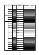
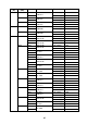
Combination of transducer, thru-hull pipe and tank Output (W) 1k/1k Frequency (kHz) 28/50 Ship type Steel FRP 28/88 Steel FRP 50/88 Steel FRP 50/200 Steel FRP 1k/2k 28/200 Steel FRP 50/200 Steel FRP 88/200 Steel FRP 2k/2k 28/50 Steel FRP 28/82 Steel FRP 28/88 Steel FRP 28/200 Steel FRP Steel FRP 38/200 Steel FRP 50/82 Steel FRP 50/88 Steel FRP 50/200 Steel FRP Steel FRP 50/200 Steel FRP 82/200 Steel FRP 88/200 Steel FRP 28/107 Steel FRP Transducer 28F-8 50B-9B 28F-8
Output (W) 2k/3k Frequency (kHz) 28/150 Ship type Steel FRP 50/107 Steel FRP 50/150 Steel FRP 3k/2k 68/200 Steel FRP 107/200 Steel FRP 3k/3k 28/38 Steel FRP Steel FRP 28/50 Steel FRP Steel FRP Steel FRP Steel FRP Steel FRP 28/88 Steel FRP Steel FRP 28/150 Steel FRP Steel FRP 28/200 Steel FRP Steel FRP 38/50 Steel FRP Steel FRP 38/88 Steel FRP Transducer 28F-18 150B-12H 50B-12 100B-10R 50B-12 150B-12R 68F-30H 200B-8/8B 100B-10R 200B-8/8B 28BL-12HR 38BL-15HR 28F-24H 38BL-15HR 28BL-1
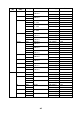
Output (W) 3k/3k Frequency (kHz) 38/150 Ship type Steel FRP 38/200 Steel FRP 50/88 Steel FRP Steel FRP Steel FRP 50/150 Steel FRP Steel FRP 50/200 Steel FRP Steel FRP Steel FRP 68/150 Steel FRP 68/200 Steel FRP 88/150 Steel FRP 88/200 1k 28 Steel Transducer 38BL-15HR 150B-12H 38BL-15HR 200B-12H 50BL-24H 88F-126H 50BL-24HR 88F-126H 50F-24H 88F-126H 50BL-24HR 150B-12H 50F-24H 150B-12H 50BL-24H 200B-12H 50BL-24HR 200B-12H 50F-24H 200B-12H 68F-30H 150B-12H 68F-30H 200B-12H 88F-126H 150B-12H
Output (W) 2k Frequency (kHz) 28 Ship type Steel Transducer 28F-18 FRP Steel 28BL-6HR FRP 38 Steel 38BL-9HR FRP 50 Steel 50B-12 FRP Steel 50BL-12 FRP Steel 50BL-12HR FRP 82 Steel 82B-35R FRP 88 Steel 88B-10 FRP 200 Steel 200B-8/8B FRP 3k 28 Steel 28F-24H FRP Steel 28BL-12HR FRP 38 Steel 38BL-15HR FRP 50 Steel 50F-24H FRP Steel 50BL-24HR FRP Steel 50BL-24H FRP 68 Steel 68F-30H FRP 88 Steel 88F-126H FRP 107 Steel 100B-10R FRP 150 Steel 150B-12H FRP 200 Ste
1. MOUNTING NOTICE Do not apply paint, anti-corrosive sealant or contact spray to coating or plastic parts of the equipment. Those items contain organic solvents that can damage coating and plastic parts, especially plastic connectors. 1.1 Display Unit WARNING Turn off the power at the switchboard before beginning the installation. Fire or electrical shock can result if the power is left on. Mounting considerations • Locate the unit out of direct sunlight.
1.3 Water Temperature/ Speed Sensor Transom mount water temperature sensor T-02MTB • Fix the cable at a convenient location on the transom with the cable clamp. • When the cable is led through the transom board, make a hole of approx. 17 mm in diameter to pass the connector. After passing the cable, seal the hole with a sealing compound.
Thru-hull mount water temperature sensor T-02MSB, T-03MSB Select a suitable mounting location considering the following points: • Select a mid boat flat position. The sensor does not have to be installed perfectly perpendicular; however, the location should not be such that the transducer may be damaged when the boat is dry-docked. • Locate away from equipment which gives off heat. • Locate away from drain pipes. • Select a location where vibration is minimal.
Through-hull mount water temperature/speed sensor ST-02MSB, ST02-PSB Select a suitable mounting location considering the following: • Select a mid-boat flat position. The sensor does not have to be installed perfectly perpendicular. The sensor must not be located where it might get damaged in dry-docking operation. • Select a place apart from equipment generating heat. • Select a place in the forward direction viewing from the drain hole, to allow for circulation of cooling water.
2. WIRING 2.1 Interconnection Refer to the interconnection diagram at the back of this manual for detailed information. Display unit rear panel (connector cover removed) MJ-A6SPF0003-050C Rectifier PR-62 DPYCY-1.5 NavNet 3D Grounding wire: As short as possible CO-SPEVV-SBC 2Px0.2SQ TTYCS-1 DPYCY-1.5 IV-2.0sq Satellite compass 100/110/115/ 220/230 VAC 1φ, 50/60 Hz Navigator High Speed/ Water temperature sensor 12-24 VDC (Connect to a dedicated breaker in the power distributor.
2.2 Wiring Standard Equipment Power cable This video sounder is designed to be powered with 12-24 VDC power. Use the cable DPYCY-1.5 (Japan Industry Standard) or equivalent. 6 3 Approx. 70 30 DPYCY-1.5 Sheath Armor Armor Sheath Sheath Vinyl tape Ǟ = 13.7 mm Conductor S = 1.5 mm 2 Ǟ = 1.56 mm (AWG16) Climp-on lug FV2-M4 Clamp armor with cable clamp. Power cable DPYCY-1.5 (JIS cable) Transducer Separate the transducer cable well away from power cables to prevent interference.
NMEA port Connect a GPS navigator, etc. to NMEA port J2 #1 to #4. You can connect two sensors (for example, GPS receiver GP-310B and smart sensor). One connects to NMEA port J2 #1 to #2 and the other connects to the NMEA port J2 #3 to #4. A satellite compass can be connected to NMEA port J2 #5 to #6. Cable connected to NMEA port: Furuno cable MJ series Approx. 30 6 Shield Cut shield here and solder vinyl wire. Clamp vinyl sheath with cable clamp.
WAGO connector (for transducer and NMEA port) Press Opener (attached inner side of shield cover). Twist. Core 2.3 1. Twist conductors 2. Insert opener and press it down. 3. Insert core to hole. 4. Release opener. 5. Pull the core to confirm to make sure it is tightly fastened.
Output sentences Sentence Data Remarks DBT Depth below transducer Ver. 1.5 DPT Depth below transducer and offset Ver. 2.0 MTW Water temperature With connection of water temperature sensor TLL Marker line position Ver. 2.
3. INITIAL SETTING This chapter provides the information necessary for initial setup of the equipment. First turn on the power and set display language. Then, set transducer used, by model number (FURUNO transducer only) or by specifications. 3.1 Language Setting 1. Press [ /BRILL] key to turn on the power. The following display appears. Language setting screen 2. Press T or S to select English as an example, and then press the ENTER key to set. The unit setting screen appears.
4. Press T or S to select necessary unit and then press the ENTER key to set. • Depth: m, ft, fa, pb, HR (Japanese unit) • Temp: °C, °F • Speed: kt, km/h, mph • Wind: kt, km/h, mph, m/h • Distance: nm, km, sm 5. Press the MENU key. The following message appears. 6. Press any key. The transducer setting screen appears. Proceed to next section. 3.2 Transducer Data CAUTION Set the transducer model number properly. Wrong transducer setting can damage the transducer and void the warranty.
Note: The “XDCR Setting” dialog box (see the illustration that follows step 1 below) only appears when turning on the power after installation, after setting the desired language and the units of measurement (see section 3.1). To open the “XDCR Setting” dialog box after completion of the transducer setting, turn off the power, then turn on the power while pressing any key. Release the key after the "XDCR Setting" dialog box appears. 1.
5. Press T or S to select the transducer frequency and then press the ENTER key. 6. Press S to select “Transducer” and then press the ENTER key. The list of programmed transducers appears. 200B-5S 50/200-1T 50/200-1ST 200B-8B 200B-12H (Example: 200 kHz) 7. Press T to select transducer connected and then press the ENTER key. 8. Jot down the alphabet which appears on the “TAP” line. You may need to change the tap setting at the rear of the display unit depending on the transducer type which is connected.
Entering transducer data by transducer specifications To connect the transducers which are not programmed, do as follows: Note: The transducers of 53 - 65 kHz, 111 to 139 kHz and 171 - 183 kHz cannot be connected to the FCV-1150 because of noise. 1. At the XDCR Setting dialog box, select “XDCR Select” and press the ENTER key. The following screen appears. XDCR Type Manual 2. Press T to select “Manual”, and then press the ENTER key. 3.
3. Press T to select "Temp" and then press the ENTER key. Temperature calibration screen 4. Press T or S to set the value for the temperature calibration and then press the ENTER key. For example, if the temperature indication is 2.5°C higher than the actual value, set “-2.5°C”. 5. To calibrate the speed value, press T to select "Speed(STW)" and then press the ENTER key. 6. Press T or S to set the value for the speed calibration and then press the ENTER key.
3.4 NMEA Port Setting If a GPS navigator and/or other sensor are connected, set up as follows. 1. Press the MENU key. 2. Press T to select "System" and "NMEA" and then press the ENTER key. NMEA setting menu 3.Press T to select the item to set and then press the ENTER key. 4.Press T or S to select an appropriate one and then press the ENTER key. Description for each item of the NMEA menu NMEA0183: Choose NMEA0183 version of navigation equipment connected to the NMEA port, among Ver. 1.5, Ver. 2.0 or Ver.
WAAS Setup: Choose how to use the WAAS signal when connecting with a WAAS receiver, for example GP-320B. The message types (WAAS-00 to WAAS-27) are used as WAAS correction. Choose WAAS-00 to enable WAAS. Note: Currently, WAAS is only available in North America, and Japan and it is in the developmental stage in Europe and Japan. During the developmental phase the reliability and availability of the WAAS signal cannot be guaranteed.
7. Press T to select “Stabi. Area“ and then press the ENTER key. 8. Press T or S to select desired Stabi. Area and then press the ENTER key. When heaving exceeds the value set here, stabilization is stopped and the stabilizer icon at the top of the screen disappears. However, the heaving mode is kept “On“. When heaving is once again less than the value set here, stabilization is restarted and the stabilizer icon reappears. 9.
APPENDIX TRANSDUCER 82B-35R The 82B-35R is a transducer with wide bandwidth of 65 kHz-110 kHz. It is constructed to provide protection against slamming. Transducer, thru-hull pipe and tank list Frquency (kHz) 28/82 50/82 Transducer 28F-18/82B-35R 50F-8G/82B-35R 50B-12/82B-35R 82/200 82B-35R/200B-8/ 200B-8B/200B-8N Hull Material Tank (Code No.) Fasten inside hull (Code No.
Setting for dual frequency transmitting 1. Set the XDCR SELECT menu as follows (see page 12 and 13). Setting for “HF” connection Setting for “LF” connection 2. Press the [PWR] key to turn the power off, and turn it on again. 3. Press the MENU key to show the menu. 4. Select [Sounder] and press the ENTER key. 5. See the section "1.20.1 Sounder menu" in the Operator's Manual for how to set "Freq Choice" and "Freq Control" for high and low frequencies.
NAME SPARE PARTS UNIT INSTALLATION MATERIALS ACCESSORIES OUTLINE 000-165-800-10 231-131 000-162-608-10 5X20 SUS304 000-147-417-10 734-230 000-157-229-10 FV2-M4 100-332-651-10 02-155-1082-1 000-157-493-10 FGMB 125V 7A PBF 000-011-708-00 CV-1150 1 Q'TY 1 5 1 2 CP02-08301 1 FP02-05700 4 SP02-05401 ** DESCRIPTION/CODE № FCV-1150-J/E (略図の寸法は、参考値です。 DIMENSIONS IN DRAWING FOR REFERENCE ONLY.
D-1
D-2
C B A 1 2 3 4 5 6 TTYCS-1(*1) OR CO-0.2x2P (*2) *3 *2 MJ-A6SPF MJ-A6SPF0003,5m,φ6 キ YEL P ミドリ GRN シロ WHT P クロ BLK P P 3 RD-A 4 RD-B 7 SHIELD NOTE *1: SHIPYARD SUPPLY. *2: OPTION. *3: CONNECTOR PLUG FITTED AT FACTORY. *4: CONNECT THE 82B-35R TRANSDUCER TO EITHER HF OR LF. 注記 *1)造船所手配。 *2)オプション。 *3)コネクタは工場にて取付済み。 *4)送受波器82B-35RはHF/LFのいずれかに接続。 無線送信機接続の場合(メニューにて設定変更) RADIO TRANSMITTER CONNECTION (CHANGE SETTING FROM MENU) *2 J2 MJ-A7SPF0013 MJ-A7SPM0001,0.
The paper used in this manual is elemental chlorine free. ・FURUNO Authorized Distributor/Dealer 9-52 Ashihara-cho, Nishinomiya, 662-8580, JAPAN Telephone : +81-(0)798-65-2111 Fax : +81-(0)798-65-4200 All rights reserved. Printed in Japan A : DEC . 2007 D : NOV . 16, 2011 Pub. No.