
Installation Instructions


6
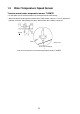
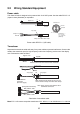
2.2 Wiring Standard Equipment
Power cable
This video sounder is designed to be powered with 12-24 VDC power. Use the cable DPYCY-1.5
(Japan Industry Standard) or equivalent.
Power cable DPYCY-1.5 (JIS cable)
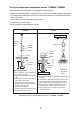
Transducer
Separate the transducer cable well away from power cables to prevent interference. Connect the
cable to the transducer port (for high frequency and/or low frequency) at the rear of the display
unit. Fabricate the cable as below.
Fabrication of transducer cable
Note: FCV-1150 cannot accept the transducers of 53 - 65 kHz, 111 to 139 kHz and 171 - 183 kHz.
Approx. 70
3
Armor
Sheath
Vinyl tape
6
Clamp armor with cable clamp.
Climp-on lug
FV2-M4
30
Sheath
Conductor
S = 1.5 mm
Ǟ = 1.56 mm
(AWG16)
2
DPYCY-1.5
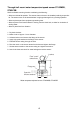
Armor
Sheath
Ǟ = 13.7 mm
Shield
Vinyl tape
Sheath
Wrap shield around sheath 30 mm and cut
excess shield. Clamp here with cable clamp.
Extract cores from here and cut inner materials.
Approx. 100
A
ttach WAGO
connector.
(See next page.)
[Composite transducer]
BLK, RED: L side
BLU, GRN: H side
Note: Never connect the shield to #2 of
the WAGO connector.
Shield
30
6
Vinyl tape