C Yo u r L o c a l A g e n t / D e a l e r 9-52, Ashihara-cho, Nishinomiya, Japan Te l e p h o n e : Te l e f a x : 0 7 9 8 - 6 5 - 2 111 0798-65-4200 All rights reserved. Printed in Japan PUB. No. IME-56090-N (TENI) FELCOM 81A/B FIRST EDITION N : : N O V. 1 9 9 6 S E P.
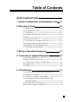
Table of Contents SAFETY INSTRUCTIONS i 1. System Configuration and Equipment Lists 1-1 2. Mounting of Units 2-1 2.1 Antenna Unit・・・・・・・・・・・・・・・・・・・・・・・・・・・・・・・・・・・・・・・・・・・・・・・・・2-1 2.2 Communication Unit ・・・・・・・・・・・・・・・・・・・・・・・・・・・・・・・・・・・・・・・2-9 2.3 Telephone・・・・・・・・・・・・・・・・・・・・・・・・・・・・・・・・・・・・・・・・・・・・・・・・・・・2-11 2.4 Terminal Unit (for class 1 only)・・・・・・・・・・・・・・・・・・・・・・・・2-12 2.5 Printer ・・・・・・・・・・・・・・・・・・・・・・・・・・・・・・・・・・・・・・・・・・・・・・・・・・・・・・・2-12 2.
. System Setup 6-1 6.1 Setting Up ・・・・・・・・・・・・・・・・・・・・・・・・・・・・・・・・・・・・・・・・・・・・・・・・・・・ 6-1 6.
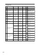
Facsimile PFX-50 Received Call Unit IC-301 (Max. 3) 100VAC 100VAC Facsimile PFX-50 Telephone FC755D1 Telephone FC755D1 Telephone FC755D1 Card Reader MCT-1540-55 PC MJ-2S MJ-2S MJ-2S MJ-2S Rosette MJ-2S DGPS Junction Box (1) IB-312 (class 1 only) Terminal Unit IB-581 Printer PP-510 Navaid AD-100 24V DC 24V DC 24V DC 100/220V AC * : CIF & NMEA are available. (No necessary to change any setting.
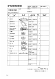
Complete Set No Name Type Code No. Mass (kg) Qty 1 Antenna Unit IB-181 --- 95 1 2 Communication Unit IB-281 --- 15 1 3 Terminal Unit IB-581 --- 6 1 Class 1 only w/Installation Materials CP16-01140 (page 1-8) 4 Telephone FC755D1 --- 1.0 1 w/Installation Materials CP16-00511(page 1-11) 5 Junction Box IB-312 --- 1.2 11 w/Installation Materials CP16-01102 (page1-9) IB-350 --- 0.5 1 Class 1 only w/Installation Materials CP16-00700 (page 1-12) IB-360 --- 0.
Optional Equipment No Name Type Code No. Mass (kg) Remarks 1 Facsimile PFX-50 --- 8.0 w/Inst. Materials CP16-00590 (page 1-13) 2 Received Call Unit IC-301 --- 0.5 w/Inst. Materials CP16-00700 (page 1-12) 3 Telephone FC755D1 --- 1.0 w/Inst. Materials 4 Modular Jack Box OP16-10 000-043-278 0.2 5 Modular Jack Box OP16-11 000-043-279 0.1 6 Modular Jack Box OP16-13 000-043-228 0.1 7 AC/DC Power Supply Unit PR-300 --- 14.
2.3 Telephone 2.3 Telephone General The telephone can be installed on a tabletop or a bulkhead. Select a location where the unit can easily be operated. For installation on a wooden table, use the mounting base and tapping screws (supplied). For installation on a steel table, fix the telephone with nuts and bolts. For bulkhead mounting, use the bulkhead mounting base (supplied with telephone accessories). Mounting location Select a location where temperature and humidity are moderate and stable.
2.10 Checking the Installation 2.10 Checking the Installation General Before turning on the system, check for proper installation, following the procedure shown below.
4.3 AC/DC Power Supply Unit PR-300 Changing the power fuse AC power sourse switch Change the power fuse according to input voltage as follows. Input Output 100/110 VAC 10 A 200/220 VAC 5A 100V 10A 220V 5A 20A ON ON OFF AC IN OFF DC IN FURUNO PR-300 Fuse for ship's mains DC power sourse switch DC OUT Figure 8 AC-DC power supply unit PR-300, rear view Ground 4-2 Connect a ground wire between ship's superstructure and a ficing screw on the PR-300.
4.4 Card Reader 4.4 Card Reader Card Reader Configuration The card reader useable with the FELCOM 81 is the MCT-1540-81 (Code No. 000-043-335). Extension cable and modem are optionally available. The card reader without installation materials is also available (Type MCT-1540, Code No. 000-043-333). Name Main Unit Type Code no.
4.4 Card Reader ・ The card reader should be installed nearest the most frequently used telephone. ・ The card reader connects to the communications unit (IB-281) of the FELCOM 81 with two connection cables (supplied) whose total length is 6.5 meters. Longer lengths are optionally available. Connection of Card Reader Connection cable ② Connection cable ① FELCOM81 IB-281 Communication Unit Card Reader Converter Connector AC adaptor ・ Power Power the card reader with 100 VAC power.
4.4 Card Reader Setting up Telephones/Facsimiles Set up telephones and facsimiles according to call application desired. Application 1. Non-credit card call only: Only non-credit card call can be made; credit card call cannot be made. 2. Credit card call/non-credit card call: Both credit card and noncredit card calls can be made. 3. Credit card call: Only credit card can be used to make call. Preset 1. Pick up receiver of No.1 telephone. 2. Dial setting desired. No.
4.5 DGPS 4.5 DGPS An L-band DGPS receiver may be connected. This requires a connector fixing plate for DGPS. CP16-01602 (Code No.: 004-442-900) Name Connector fixng plate Type Code No. Qty CP16-01606 004-442-910 1 PH5P-L200-SMP2P 000-141-558 1 PH2P-L300-SMR2P 000-141-559 1 M4 × 8 000-881-445 4 Cable assy Pan head screw 1. Turn off the communication unit. 2. Detach the cover. 3. Detach the dummy plate from the rear panel.
5.2 Setting of Telephone 5.2 Setting of Telephone Change dialing format from dial to pushbutton as follows. (The handset should be hung in the hanger.) FC622SLIWG FC755D1 1. Press the STO key. 2. Press the # key. 3. Press the * key to display "Pb." 4. Press the STO key again. 1. Insert tip of a mechanical pencid under plastic cover to remove cover, and then remove memo paper. 2. Use the tip of the mechanical pencil to set DIP Switch.
5.4 Attaching the Compass Safe Distance and Inmarsat B Seals 5.4 Attaching the Compass Safe Distance and Inmarsat B Seals Attach the compass safe distance seals (supplied with installation materials) for the units shown below. When the same units (for example: telephone, facsimile, etc.) are used for other than FELCOM 81, attach ""seals b to them to distinguish.
5.5 Facsimile PFX-50 Setting 5.5 Facsimile PFX-50 Setting Turn on the power while dialing [*], [1], [3] to initialize the PFX-50's memory. Change the dial mode to "push button" with the MODE switch. (Choose position "T". ) Dial Mode MODE Switch Chosse "T".
5.6 Personal Computer Connection 5.6 Personal Computer Connection You can use a personal computer as the terminal unit for the FELCOM81, by installing the contents of a program disk on the PC. Note: Basic knowledge of DOS commands is required. 16-501-091 Requirement; Type : Code No: 004-441-520 Booting up by disk drive 1. Format a floppy disk (command "format / s " ). Refer to PC operator's manual about formatting. 2. Copy the following three files from program disk to formatted floppy disk : B TERM.
6. System Setup 6.1 Setting Up Overview Set up the terminal unit, editor screen and communication unit (Class 2). When there is no navigation input or gyro input, enter them manually referring to operator's manual. Turn on the Main Unit and Terminal Unit. After a while, the Main Menu, shown below, appears. File Edit Telex Setup BRK (Nov-10-96 16:25) Date Standby Display Setting up Key Operation 1. Terminal Unit ・・・・・・・・・・・・・・・・・・ Entry of date, answerback code, etc. F4 ⇒ 3 See next page. 2.
6.2 Registering Answerback Code (Class 1 only) 6.2 Registering Answerback Code (Class 1 only) Overview Enter ship's answerback code at installation. The answerback code cannot be changed once registered. Confirm the code before pressing the Enter key. Procedure Press F4 , display. Cursor 3 and in this order at standby- 8 !! ATTENTION: CAN NOT REENTER !! Enter your ship's answerback code given by Inmarsat, then press the Enter key.