FI-504 MULTI Instrument www.furuno.co.
The paper used in this manual is elemental chlorine free. ・FURUNO Authorized Distributor/Dealer 9-52 Ashihara-cho, Nishinomiya, 662-8580, JAPAN Telephone : +81-(0)798-65-2111 Fax : +81-(0)798-65-4200 All rights reserved. Printed in Japan A : OCT . 2007 A1 : OCT . 17, 2007 Pub. No.
IMPORTANT NOTICES • The descriptions in this manual are intended for readers with a solid knowledge of English. • No part of this manual may be copied or reproduced without written permission. • If this manual is lost or worn, contact your dealer about replacement. • The contents of this manual and equipment specifications are subject to change without notice. • The example screens (or illustrations) shown in this manual may not match the screens you see on your display.
SAFETY INSTRUCTIONS SAFETY INSTRUCTIONS The operator of this equipment must read these safety instructions before attempting to operate the equipment. WARNING Indicates a potentially hazardous situation which, if not avoided, could result in death or serious injury. CAUTION Indicates a potentially hazardous situation which, if not avoided, may result in minor or moderate injury.
TABLE OF CONTENTS FOREWORD .............................................................................................. iv SYSTEM CONFIGURATION ....................................................................... v 1.OPERATION ............................................................................................. 1 1.1 1.2 1.3 1.4 1.5 1.6 1.7 1.8 Operating Controls, Display Layout...................................................................... 1 Turning the Power On/Off ...................
FOREWORD FOREWORD A Word to the Owner of the FI-504 Congratulations on your choice of the FURUNO FI-504 Multi Display, a member of the FI-50 series of marine instruments. We are confident you will see why the FURUNO name has become synonymous with quality and reliability. For over 50 years FURUNO Electric Company has enjoyed an enviable reputation for quality marine electronics equipment. This dedication to excellence is furthered by our extensive global network of agents and dealers.
SYSTEM CONFIGURATION Standalone configuration NMEA 2000 Sensor (ex. Smart Sensor) : Standard Supply : Optional Supply : Local Supply 12 VDC NOTICE: Turn on the terminal resistor in the instrument when connecting an NMEA 2000 sensor. For the procedure, see the section on setting up, in the installation chapter.
SYSTEM CONFIGURATION NMEA 2000 network FI-5001 WIND TRANSDUCER TERMINAL BOX (where necessary) FI-504 MULTI FI-501* and/or FI-502 FI-505 COURSE PILOT FI-506 RUDDER FI-503 DIGITAL 30 NMEA 2000 SENSOR* NMEA 2000 SENSOR* NMEA 2000 SENSOR* NMEA 2000 SENSOR* NMEA 2000 SENSOR* JUNCTION BOX FI-5002 * NMEA 2000 SENSORS - Boat speed - Depth - Heading - Navigation - Environment - Autopilot - Engine *FI-501 Wind Angle FI-502 Close Hauled Wind Angle 12 VDC (not necessary if powered by NMEA 2000 network) :
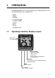
1. OPERATION Provided applicable sensors are connected, the FI-504 provides the following information, all on a backlit LCD: • • • • • • • • • 1.1 Depth Speed Heading Environment data Autopilot (rudder) Engine Wind Timers Navigation data Operating Controls, Display Layout Mode name (Ex. SPD=Speed) SELECT/CLEAR - Select menu option. - Silence alarm. - Clear data. - Reset counters and indcations. - Increment value. APP/TRUE - Select apparent or true (wind) alternately. - Decrement value.
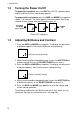
1. OPERATION 1.2 Turning the Power On/Off To power the instrument, press the DISP key. All LCD segments go on and off and then the last-used display appears. To power off the instrument, press the DISP and MODE keys together (about 7-10 seconds). The timer appears and counts down from three seconds to one second, and then the power goes off. POWER Press DISP and MODE keys together 3 POWER 2 POWER 1 POWER OFF Power OFF sequence 1.3 Adjusting Brilliance and Contrast 1.
1. OPERATION 1.4 Selecting a Display Use the DISP key to select a display category. Select desired display with the MODE key.
1. OPERATION 1.4.1 Display description Depth category Display title Current depth Shallow alarm Indication DPTH SHALLOW Deep alarm DEEP Shallow anchor alarm SHALLOW Deep anchor alarm DEEP Function Current depth, in meters, feet or fathoms. Set shallow depth alarm. Audio and visual alarms are released when the depth is lower than the threshold value. Set deep depth alarm. Audio and visual alarms are released when the depth is higher than the threshold value. Set shallow anchor alarm.
1. OPERATION Timer category Display title Indication Count up timer UP Count down timer 1 DOWN 1 Count down timer DOWN 2 Function Count-up timer. Count-down timer 1. Count-down timer 2.
1. OPERATION Heading category Display title Current heading Indication HDG Average heading HDG AVG Heading on next tack TACK Course over ground Course made good Distance made good COG CMG DMG Function Heading, in degrees. Bearing reference in Magnetic (MAG) or True (TRUE). Average heading, in degrees. Bearing reference in Magnetic (MAG) or True (TRUE). Heading on next tack, in degrees true (fixed). Bearing reference in Magnetic (MAG) or True (TRUE). Course over ground, in degrees.
1. OPERATION Environment category Display title Battery voltage Minimum battery voltage alarm Indication VOLTS VOLTS LO Time - Date Water temperature Air temperature Air pressure Humidity Wind chill temperature WATER AIR° HPA HUMID CHILL Dew point DEW Function Battery voltage. Set low battery voltage alarm. Audio and visual alarms are released when the battery voltage goes lower than the threshold value. Current time, in 12-hour or 24-hour format. Current date. Water temperature, in °C or °F.
1. OPERATION 1.5 Selecting Apparent or True Wind Angle, Wind Speed You can show wind angle and wind speed in apparent or true wind. The apparent wind is the actual flow of air acting upon a sail, or the wind as it appears to the sailor. True wind is the wind seen by a stationary observer in velocity and direction. WIth a wind angle or wind speed indication displayed, press the APP/ TRUE key to change the wind angle or wind speed to apparent and true alternately.
1. OPERATION 1.7 Alarms There nine conditions which trigger audio and visual alarms: Shallow alarm, Deep alarm, Shallow anchor alarm, Deep anchor alarm, Max. true wind speed alarm, Low true wind speed alarm, High apparent wind angle alarm, low apparent wind angle alarm, and low battery voltage alarm. 1. Use the DISP and MODE keys to select desired alarm page, referring to the illustration below for alarm location.
1. OPERATION Alarm description Alarm Low battery voltage alarm Alarms released when; battery voltage is lower than this threshold. Setting range 5.0 - 20.0 volts 2. If the selected alarm page shows “Off,” press and hold down the SELECT/CLEAR key until an alarm setting appears. 3. Press the APP/TRUE and SELECT/CLEAR keys together to enable adjustment. The alarm setting starts flashing. 4. Press the APP/TRUE key to lower the setting; the SELECT/CLEAR key to raise it.
1. OPERATION 1.8 Timers Three timers are provided: • Count-up timer (stopwatch) • Count-down timer (two provided) Time is displayed in seconds or minutes, depending on counter values. Once you have set a timer, you can leave that page and select any other display. The counter continues to run in the background. Count-up timer The count-up timer functions like a stop watch, counting time upward, to 99 hours, 99 minutes and 59 seconds.
1. OPERATION To stop or restart the timer, press the SELECT/CLEAR key momentarily. A short beep sounds when the timer is stopped or restarted. To stop and reset the timer to start value, press the SELECT/CLEAR key until you hear a long beep. The timer is stopped and reset to start value. The timer settings are reflected on any timer-equipped instrument in the network which is set up for synchronization.
2. MAINTENANCE, TROUBLESHOOTING This chapter provides the information necessary for keeping your equipment in good working order. WARNING Do not open the equipment. Only qualified personnel should work inside the equipment. 2.1 Preventive Maintenance Following the recommended procedures below will help maintain performance. Check item Check point Remedy Cabling Check that all cabling is Reconnect if necessary. Replace if damaged. securely fastened and is free or rust and corrosion.
2. MAINTENANCE, TROUBLESHOOTING 2.2 Troubleshooting If you feel the equipment is not functioning properly, follow the procedures in the table below to try to restore normal operation. If normal operation cannot be restored, do not attempt to check inside the cabinet. There are no user-serviceable parts inside. Troubleshooting Problem Possible cause Display is • Power supply blank. Panel is • Cabling disconnected or not lit. damaged. Power is on but no or some data. Inaccurate data • Check power supply.
3. INSTALLATION NOTICE Do not apply paint, anti-corrosive sealant or contact spray to coating or plastic parts of the equipment. Those items contain organic solvents that can damage coating and plastic parts, especially plastic connectors. 3.1 Equipment Lists Standard supply Name Display Unit Installation Materials Type FI-504 CP26-00600 Code No. 000-011-744 Qty 1 1 set Remarks See packing list at end of manual for details. Optional supply Name Cable Assy.
3. INSTALLATION 3.2 Mounting The display unit can be installed two ways: surface mount (fixed at front panel or fixed from rear panel) and flush mount (optional kit required). This section covers surface mounting. For flush mounting, see the flush mounting instructions, issued separately. Surface mount 1: Fix instrument from front panel 1. Using the template at the back of this manual, open a mounting hole in the installation site. 2. Detach the front panel together with the keypad assy.
3. INSTALLATION Surface mount 2: Fix instrument from rear panel 1. Using the template at the back of this manual, open a mounting hole in the installation site. 2. Insert studs (M3×40, 2 pcs., supplied) in the holes shown below. (Use only the studs supplied.) Insert stud here. 3. Set the display unit to the mounting hole, inserting studs through respective holes. Fix the display unit with wing nuts (M3, supplied).
3. INSTALLATION 3.3 Wiring 3.3.1 Standalone configuration For standalone configuration the junction box is not necessary; connect the instrument directly to the power supply. – Black NMEA 2000 drop cable NMEA 2000 SENSOR + Red 12 VDC FI-50-DROP Cable (6 m) Display Unit FI-504 . 3.3.2 Multi-instrument configuration FI-50-CHAIN (0.3 m: Std, 1/5/10/20 m: Option) DISP. UNIT FI-501/502/FI-503/FI-505/FI-506 DISP. UNIT (Instruments can be connected FI-504 in any order.
3. INSTALLATION Junction box (option) The junction box is required when connecting NMEA 2000 network. This section covers wiring of the junction box. For how to mount the junction box, see its installation instructions, issued separately. 12VDC CN3 CN4 DROP DROP CN5 DROP BACKBONE 12 VDC FI-501/502/503/504/505/506 NMEA2000 DEVICE Fix cable with cable tie (supplied). CH3 DROP - CH5 DROP and BACKBONE are socket-and-plug-type terminal blocks.
3. INSTALLATION Terminal resistor The illustration below show various system configurations and what units to activate the terminal resistor.
3. INSTALLATION Turn on the terminal resistor in the junction box when the NMEA 2000 sensor(s) connected to it do not have a terminal resistor. Terminal Resistor OFF: ON: For how to turn on the terminal resistor in a FI-50 series instrument, see page 33 (FI-501//FI-502/FI-505) or page 35 (FI-506). 3.4 Setting Up Your instrument is pre-programmed with factory default settings, which may or may not be suited to your vessel. Therefore, it is necessary to initialize the instrument for use with your vessel.
3. INSTALLATION . DPTH M DEPTH Depth unit SPD RES RES CAL LOG NM 1.0 TIMER LOG unit WIND CAL 3 SPD RES VMG response S CAL 0 Speed unit SOG HR 12 Time format RES CAL 3 3 KT WINDADJ CAL CAL 1.
3. INSTALLATION Setup1 menu items Display DPTH M Function Select depth unit. CAL Set depth offset. DEPTH Setting range or options M (Meter), FT (Feet) Default setting M -99 - +99 0.0 CAL 0.0 SHWLOCK Lock/unlock shallow alarm setting. ON, OFF OFF Set depth response. The lower the 0 - 12 setting the faster the response to change in depth. 3 CAL 0 OFF DPT RES CAL F 3 SPD KT Select speed unit. KT (Knot), KT MPH (Miles/Hour), KMH (Kilometers/Hour) Select speed resolution.
3. INSTALLATION Setup1 menu items Display SPD RES CAL 0 SOG RES CAL 0 0 VMG RES CAL Setting range or options Set speed response. The lower the 0 - 12 setting the faster the response to change in speed. Default setting 0 Set SOG response. The lower the 0 - 12 setting the faster the response to change in speed over ground. 0 Set VMG response. The lower the 0 - 12 setting the faster the response to change in velocity made good. 3 Enable/disable the timer alarm’s audio alarm.
3. INSTALLATION Setup1 menu items Display HDG MAG Function Select true or magnetic bearing. CAL HDGLOCK CAL LOC HDG RES CAL 0 TIME HR Select heading type to display when activating locked heading. Setting range or options MAG (Magnetic), TRU (True Default setting MAG LOC (Locked), CUr (Current) LOC Set heading response. The lower 0 - 12 the setting the faster the response to change in heading. 0 Select time format. 12 12, 24 (hour) CAL 12 --- ---:--- --CAL 2 0 TEMP C Use local time.
3. INSTALLATION 3.4.2 Setup2 menu The setup 2 menu contains user settings which once preset do not require frequent adjustment. 1. Press and hold down the APP/TRUE and SELECT/CLEAR keys together (about 5-6 seconds) to enable the user settings menu. The software version of CPU1 appears. (See the illustration below.) 2. Press the DISP key to choose menu item. Each press of the key changes the menu item in the sequence shown below. *XXxx=program and program ver. nos.
3. INSTALLATION Setup2 menu items Display XXxxx XXxxx KEYBEEP Setting range or options Function Default setting Software version of CPU1. XX=program no. and xxx=program version no. - - Software version of CPU2. XX=program no. and xxx=program version no. - - Turn key beep on/off. ON, OFF ON Auto brilliance on/off. ON, OFF ON CAL ON A BRILL CAL ON ALT CAL OFF SETUP CAL OFF OFF 1: Depth/boat spd 2: Boat spd/water temp. 3: Depth/water temp. 4: Depth/boat spd/water temp.
3. INSTALLATION Setup2 menu items Display TIMER Turn timer displays on/off. Setting range or options ON, OFF Default setting ON Turn wind displays on/off. ON, OFF ON Turn heading displays on/off. ON, OFF ON Turn navigation displays on/off. ON, OFF ON Turn environmental displays on/off. ON, OFF ON Turn autopilot displays on/off. ON, OFF ON Turn engine displays on/off. ON, OFF ON Demo mode. To enable, press the SELECT/CLEAR key. Depth is shown.
FI-504 MULTI SPECIFICATIONS OF FI-504 MULTI 1 GENERAL 1.1 Display 1.2 Display Content 1.3 I/O Port 2 JUNCTION BOX (OPTION) 2.1 No. of I/O ports NMEA 2000 Device NMEA 2000 Backbone 3 12 VDC, less than 0.1 A 12 VDC, less than 1 A, max. 2A connectable ENVIRONMENTAL CONDITIONS 4.1 Useable Temperature Range 4.2 Relative Humidity 4.3 Waterproofing Display Unit Junction Box 4.4 Vibration 5 6 ports 2 ports POWER SUPPLY AND POWER CONSUMPTION 3.1 Display Unit 3.
NAME OUTLINE INSTALLATION MATERIALS UNIT FI-504 000-167-804-10 M3X40 SUS304 000-167-826-10 M3 SUS304 000-167-453-10 M3 SUS304 000-167-404-10 M3 SUS304 000-163-884-10 3X20 SUS304 000-167-832-10 TZ7583002AO 100-340-471-10 19-028-3124-1 000-011-745-00 FI-504 1 Q'TY 2 2 2 2 4 1 1 CP26-00600 DESCRIPTION/CODE № LIST (略図の寸法は、参考値です。 DIMENSIONS IN DRAWING FOR REFERENCE ONLY.
A-2 フラッシュマウントキット INSTRUMENTS FLUSH MOUNT KIT. FI-50 番 号 NO. 名 称 NAME CODE NO. 000-010-619-00 TYPE FI-50-FLUSH-KIT 用途/備考 REMARKS ※1 前面パネルF 1 1/1 数量 Q'TY 型名/規格 DESCRIPTIONS 略 図 OUTLINE 26AA-X-9401 -3 TZ7580002A0 FRONT PANEL 1 CODE NO. 000-167-885-10 ※1に貼付済み PRE-ATTACHED TO ※1. FURUNOロゴH3 2 19-028-1502-0 FURUNO STICKER H3 1 CODE NO. 100-339-580-10 ハードカバーF 3 TZ7580007AO COVER 1 CODE NO. 000-167-887-10 フラッシュマウントツール 4 TZ7580008AO FRAME 1 CODE NO.
Jul.24'07 R.
Jul.24'07 R.
Jul.24'07 R.
C B A 1 2 3 4 5 1 2 3 4 5 1 2 3 4 5 DROP SHIELD NET-S NET-C NET-H NET-L DROP SHIELD NET-S NET-C NET-H NET-L DROP SHIELD NET-S NET-C NET-H NET-L BACKBONE SHIELD NET-S NET-C NET-H NET-L 1 2 3 4 5 接続箱 JUNCTION BOX NMEA2000 NETWORK (BACKBONE) 1 2 3 4 5 DROP SHIELD NET-S NET-C NET-H NET-L BACKBONE SHIELD NET-S NET-C NET-H NET-L 1 2 3 4 5 1 2 3 4 5 DROP SHIELD NET-S NET-C NET-H NET-L 接続箱 JUNCTION BOX NMEA2000 NETWORK (BACKBONE) FI-5002-POWERCABLE,2m アカ RED (VV-SA0.
タッピンネジ用穴(4ヵ所) For tapping screws (4 pcs.) 寸切りボルト用穴(2ヵ所) For bolts (2 pcs.
FI-50シリーズ 表示部 フラッシュマウント用型紙 FI-50 series Display unit Flush Mount Template