OPERATOR'S MANUAL COLOR INSTRUMENT Model FI-70 www.furuno.
The paper used in this manual is elemental chlorine free. ・FURUNO Authorized Distributor/Dealer 9-52 Ashihara-cho, Nishinomiya, 662-8580, JAPAN All rights reserved. Printed in Japan A : JAN . 2015 A1 : FEB . 16, 2015 Pub. No.
IMPORTANT NOTICES General • This manual has been authored with simplified grammar, to meet the needs of international users. • The operator of this equipment must read and follow the descriptions in this manual. Wrong operation or maintenance can cancel the warranty or cause injury. • Do not copy any part of this manual without written permission from FURUNO. • If this manual is lost or worn, contact your dealer about replacement.
SAFETY INSTRUCTIONS p q p WARNING Indicates a potentially hazardous situation which, if not avoided, could result in death or serious injury. CAUTION Indicates a potentially hazardous situation which, if not avoided, can result in minor or moderate injury. Warning, Caution Mandatory Action Prohibitive Action Safety instructions for the operator Safety instructions for the installer WARNING WARNING Do not open the equipment. Only qualified personnel should work inside the equipment.
TABLE OF CONTENTS FOREWORD .................................................................................................................... v SYSTEM CONFIGURATION .......................................................................................... vi EQUIPMENT LISTS....................................................................................................... vii 1. OPERATION AND CONTROLS OVERVIEW........................................................1-1 1.1 1.2 1.3 1.4 1.5 1.6 1.7 2.
TABLE OF CONTENTS 4. SYSTEM MENU .....................................................................................................4-1 4.1 CAN bus (NMEA2000) Network Shared Settings ...................................................... 4-1 4.1.1 How to adjust the sharing level ...................................................................... 4-2 4.2 How to Share Language and Brilliance Settings Between FI-70s.............................. 4-3 4.3 How to Set the Display Format ....................
FOREWORD A Word to the Owner of the FI-70 Congratulations on your choice of the FURUNO FI-70 Color Instrument. We are confident you will see why the FURUNO name has become synonymous with quality and reliability. Since 1948, FURUNO Electric Company has enjoyed an enviable reputation for quality marine electronics equipment. This dedication to excellence is furthered by our extensive global network of agents and dealers.
SYSTEM CONFIGURATION Analog sensors Tank gauge Wind Transducer FI-5001/L Speed/Temp. Sensor ST-02MSB/ST-02PSB Color Instrument FI-70 (Maximum 11 units) Analog NMEA Data Converter IF-NMEAFI + 12 VDC to 15 VDC CAN bus/NMEA2000 sensors T-connector (option) Junction Box FI-5002 CAN bus/NMEA2000 Backbone Terminal resistor* (option) Terminal resistor* (option) *: Terminal resistors must be installed at both ends of the backbone.
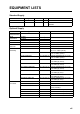
EQUIPMENT LISTS Standard Supply Name Color Instrument Installation Materials Type FI-70 CP26-02000 Code No. 000-027-046 Qty 1 1 Remarks Includes soft cover. Contains CP26-02001 installation materials. Optional Supply Name Type Analog NMEA IF-NMEAFI Data Converter Wind FI-5001 Transducer FI-5001L Junction Box FI-5002 Front Mount Kit OP26-29 Installation CP26-00300 Materials CP26-00400 Cable FI-50-CHAIN-0.
EQUIPMENT LISTS This page is intentionally left blank.
1. OPERATION AND CONTROLS OVERVIEW 1.1 Controls A Display area AWA 50º 㻼㼞㼑㼢 㻲㼡㼚㼏 㻺㼑㼤㼠 Power/Brill key Left Software key Key indications Menu/Back key Function key Right Software key The information shown in the display area varies depending on the category chosen to be displayed. Key Power/Brill key Software keys Function key Key indications Menu/Back key 1.2 Functions Turn power on/off; open the [Brilliance] setting window.
1. OPERATION AND CONTROLS OVERVIEW 1.3 How to Adjust the Screen Brilliance Press the Power/Brill key to show the [Brilliance] setting window. The software keys decrease or increase brilliance. Brilliance Pressing the Power/Brill key repeatedly cycles through the brilliance levels. Press the function key to switch between Day and Night modes. Press function key to switch between modes. Day Mode Night Mode Note: When the FI-70 is subjected to undue heat, the brilliance may automatically darken.
1. OPERATION AND CONTROLS OVERVIEW 1.4 Menu Overview 1. Press the Menu/Back key to display the main menu. The main menu contents change according to the current category (See section 1.7 for more information on categories). In the example below, the wind category is displayed. Category specific menu items are displayed above the Main menu items. Wind Speed Wind Angle Alarms Main menu starts below the category specific menu items.
1. OPERATION AND CONTROLS OVERVIEW Main menu items The main menu has the following menu items which appear in all menus, regardless of the category selected: Menu item [Alarms] [Disp Config] [Alarm Log] [Sensor in Use] [System] Description Set alarms. (See section 6.3 for details on the [Alarm] menu.) Change the information displayed on each page. (See section 1.7 for more information.) Open the alarm log. (See section 6.3 for more information.
1. OPERATION AND CONTROLS OVERVIEW 1.7 Screen Categories and Page Setup The FI-70 can display the information categories shown in the figures below, provided a sensor for the appropriate information is connected. 30min 10 15 4300 HDG 348 20 º 4400 kn SOG 17.8 Compass Speed WAYPOINT RPM Eng. Temp. 3280 125.6 Depth 4303 4500 ft Graphs Engine Rudder Time P 30 XTE 10 x1000 STW T 20 º 00:15:00 00:00:00 0.
1. OPERATION AND CONTROLS OVERVIEW 1.7.1 How to change the displayed page The FI-70 can display up to seven different pages of information. Use the software keys to change pages backwards and forwards between the pages. The number of the current page is displayed as a large numeral in the center of the screen for three seconds after the page is displayed. Pages with no display information selected are skipped. In the example below, no information is selected to be displayed on pages 2, 5 or 7.
1. OPERATION AND CONTROLS OVERVIEW 1.7.2 How to set up pages The FI-70 is capable of displaying seven pages of category information. The procedure below outlines how to set up a page. 1. Press the Menu/Back key to display the main menu. 2. Press the right software key to scroll down the menu and highlight [Disp Config], then press the function key. T Select a page to setup. AWA 50º Prev Ent Next 3. Press the software keys to select the appropriate page.
1. OPERATION AND CONTROLS OVERVIEW 3) Press the software keys to select the appropriate data to display, then press the function key. Depth Depth is shown on graph A Temp. Water temperature is shown on graph Atmospheric temperature is shown on graph A Press. Atmospheric pressure is shown on graph W Temp. 4) Repeat steps 2) and 3) for the second graph. 5) Press the right software key to select [Done], then press the function key to apply the changes. 6) Press the Menu/Back key once to close the menu.
2. DISPLAY CATEGORIES AND CATEGORY SPECIFIC MENUS This chapter explains the various menu operations and on-screen indications for each display category. Depending on the data currently selected to be displayed, the analog and digital data displayed on-screen may differ. 2.1 Compass Category Compass needle HDG Heading reference T: True M: Magnetic T 348 º Press the function key to change data displayed The compass needle indicates the current heading in this category.
2. DISPLAY CATEGORIES AND CATEGORY SPECIFIC MENUS 2.2 Speed Category Speed Thru Water (STW) screen Speed Over Ground (SOG) screen Current speed 10 15 10 STW 20 5 kn SOG 0 15 SOG 17.8 20 5 Press the function key to change data displayed kn STW 0 17.8 This category displays the ship speed data on the needle meter. When there is no speed data input to the FI-70, the current speed indicator (needle) is not displayed. The Speed category has two available screens: STW and SOG.
2. DISPLAY CATEGORIES AND CATEGORY SPECIFIC MENUS 2.3 Engine Category NOTE: Data shown in the engine category is input from engine sensors. Always check any malfunction at the engine, do not rely solely on the FI-70 indications. 1 Engine RPM 2 Currently selected gear is highlighted. F: Forward, N: Neutral, R: Reverse 3 Status indications 4 Press function key to change data displayed. x1000 RPM Eng. Temp. 3280 125.6 1 3 Eng. Temp. ºF 136°F -16°F Eng. Temp.
2. DISPLAY CATEGORIES AND CATEGORY SPECIFIC MENUS 2.4 Graph Category 30min 20 10 30min 20 10 4300 4300 Depth 4256 20 30min 4400 4400 ft 10 1000 Depth 4303 A Press. 1003 4500 ft hPa 990 The graph category displays preselected sensor data in graph format. Up to two graphs can be displayed simultaneously. The following data may be selected for display in graph format. • Depth • W Temp. (Water temperature) • A Temp. (Atmospheric temperature) • A Press.
2. DISPLAY CATEGORIES AND CATEGORY SPECIFIC MENUS 2.5 Highway Category Destination/Waypoint name WAYPOINT Destination/Waypoint mark Own ship mark XTE 0.05 P Press the function key to change data displayed. MN The highway display provides a graphic presentation of your boat’s track along the intended course, toward a waypoint. Press the function key to cycle through the following data on the Highway display: Displayable data XTE WPT RNG BRG Description Displays the XTE (Cross Track Error).
2. DISPLAY CATEGORIES AND CATEGORY SPECIFIC MENUS 2.7 Timer Category Time Time 00: 15:00 1 00:00:00 2 Lap 00:15:00 00:00:00 Trip Countdown Timer1 0 NM 1 2 3 Countdown Timer2 Time 00:00:00 00:00:00 4 Lap Trip 0 NM 2 3 1 Countdown Timer 2 Lap time 3 Trip meter 4 Countup Timer Countup Timer The Timer category has three available timers to select from, as indicated in the figure above. To select the desired timer, see "How to set up pages" on page 1-7.
2. DISPLAY CATEGORIES AND CATEGORY SPECIFIC MENUS 2.7.2 How to adjust the timers 1. With the timer screen displayed, press the function key to show the [Func] key indications. The left software key indication is blank for the [Countup] timer. Setup Start Reset Note: The [Countup] timer does not require setup. When using the [Countup] timer, skip to step 4. 2. Press the left software key to open the [Setup] window. The time will flash, indicating it can be changed.
2. DISPLAY CATEGORIES AND CATEGORY SPECIFIC MENUS 2.8 Wind Category 4 1 A 4 AT 1 AWA 3 50º Wind Angle 1 Wind Angle 4 2 AWA AWA 27º 3 AWA 3 Ch Wind 2 Ground Wind* A 27º Ground Wind 3 Data display 4 Display mode T: True A: Apparent *: Heading, AWA/AWS and ship speed data are required to display Ground Wind This category displays various wind data. There are three wind modes available, as shown in the figure above.
2. DISPLAY CATEGORIES AND CATEGORY SPECIFIC MENUS 2.9 AIS Category H-UP N-UP N NM Heading Up NM North Up The AIS category displays basic AIS data such as bearing, range, lost and dangerous targets. The maximum number of targets which may be displayed is 25, in order from closest to farthest from own ship. Range rings are fixed at 2 NM, 4 NM and 6 NM. There are two orientations available: • [Heading Up] - Displays the targets and own ship with the heading oriented upwards.
2. DISPLAY CATEGORIES AND CATEGORY SPECIFIC MENUS 2.9.1 How to display AIS target details 1. Press the function key to show the AIS key indications, as shown in the figure below. AIS N Detail 2. Press the left software key to cycle through the targets, in order, from closest to farthest. Press the right software key to cycle through the targets, in order, from farthest to closest. 3. Press the function key to select a target and display its details.
2. DISPLAY CATEGORIES AND CATEGORY SPECIFIC MENUS 2.10 Custom Box Category Depth W Temp. 3855 ft SOG º COG M 42.5 kn POSN 65 F 345 º 34º37.145’N 75º29.108’W The Custom Box category allows you to customize the display, dividing the display area with up to 6 boxes. The boxes may be set up to display all manner of sensor data of simple graphic data (such as roll and pitch). The Custom Box category may be selected from the [Disp Config] menu. See "How to set up pages" on page 1-7 for details.
2. DISPLAY CATEGORIES AND CATEGORY SPECIFIC MENUS 2.10.1 How to customize the data boxes With the Custom Box screen displayed, the key indications show "Edit" as the function key function. 1. Press the function key to begin customizing the boxes. The selected box is highlighted in blue. Selected box is highlighted in blue. Depth W Temp. 3855 ft 19.5 SOG ºF COG M 345 º 42.5 kn POSN 34º37.145’N Prev 75º29.108’W Ent Next 2.
2. DISPLAY CATEGORIES AND CATEGORY SPECIFIC MENUS 2.10.2 How to resize data boxes 1. With the Custom Box category displayed, press the function key. 2. Press the software keys to highlight the data box to be resized, then press the function key. 3. Press the software keys to select [Select Box Size], then press the function key. Resizes types available BRG M 30 º Depth COG M 3855 ft 345 º Ent 4.
2. DISPLAY CATEGORIES AND CATEGORY SPECIFIC MENUS 2.10.3 Data which may be displayed in custom boxes The table below shows the data which may be displayed in custom boxes and the box sizes available when resizing the boxes. Data type Speed Wind Displayed data STW SOG STW Max*1 SOG Max*1 STW Avg.*1 VMG AWS TWS SOG Avg.*1 TWS Max*1 GWD M(T) HDG M(T) Heading Course Navigation HDG Avg.
3. ALARMS This section explains how to set and use the [Alarms] menu. Most alarms may be accessed from the respective category menu, however, settings made in the [Alarms] menu are applied to each category. To access and set alarm from the [Alarms] menu, do the following: 1. Press the Menu/Back key to open the menu. 2. Press the software keys to select [Alarms], then press the function key to show the [Alarms] menu.
3. ALARMS 3.2 STW Alarm and SOG Alarm The STW and SOG alarms set a high speed or low speed alarm threshold. When the vessel speed goes over the high speed threshold, or below the low speed threshold, the alarm is activated. 1. Access the [Alarms] menu, using the procedure outlined on page 3-1. 2. Press the software keys to select [STW Alarm] or [SOG Alarm], then press the function key. 3. [Alarm] is highlighted, press the function key. 4.
3. ALARMS 3.3 Wind Speed/Direction Alarms 3.3.1 TWS alarm The TWS alarm sets a true wind speed alarm threshold. When the TWS goes over the set threshold, the alarm is activated. 1. Access the [Alarms] menu, using the procedure outlined on page 3-1. 2. Press the software keys to select [Max TWS Alarm], then press the function key. 3. [Alarm] is highlighted, press the function key. 4. Select [OFF] or [ON] as appropriate, then press the function key. • [OFF]: Disable the alarm. Proceed to step 7.
3. ALARMS 3.4 Trip Alarm The trip alarm is activated when the total distance traveled reaches the set threshold. The total distance traveled is calculated from the moment the FI-70 is powered for the first time. This distance is stored in the trip log. 3.4.1 How to set the trip alarm 1. Access the [Alarms] menu, using the procedure outlined on page 3-1. 2. Press the software keys to select [Trip Alarm], then press the function key. 3. [Alarm] is highlighted, press the function key. 4.
3. ALARMS 3.5 Depth Alarm The depth alarm activates when the depth is either above or below the set threshold. 1. Access the [Alarms] menu, using the procedure outlined on page 3-1. 2. Press the software keys to select [Depth Alarm], then press the function key. 3. [Alarm] is highlighted, press the function key. 4. Select [OFF], [Deep] or [Shallow] as appropriate, then press the function key. • [OFF]: Disable the alarm. Proceed to step 7.
3. ALARMS 3.7 Water Temperature Alarm The water temperature alarm warns you when the temperature goes over or under the set threshold. The average temperature may also be used as a threshold and is calculated over one minute intervals. 1. Access the [Alarms] menu, using the procedure outlined on page 3-1. 2. Press the software keys to select [W Temp. Alarm], then press the function key. 3. [Alarm] is highlighted, press the function key. 4.
3. ALARMS 3.8 Engine Alarms The engine alarm is activated when the FI-70 receives information containing errors or alarms from the engine. The indicators shown in the table below are normally displayed in gray when the engine category is selected. When an alarm is active, the corresponding indicator flashes and the color changes to an orange-red. Indicator Cause/location of problem Engine control system. Battery. Coolant. Oil pressure. 1.
3. ALARMS 3.9 Anchor Alarm The anchor alarm activates when the vessel exceeds the selected distance from the point at which the alarm was set, or the depth is higher/lower than the depth threshold setting. This alarm is useful when at a standstill or not at the helm. Where Anchor Alarm is set to [Depth] Where Anchor Alarm is set to [Distance] Distance threshold Depth at which the alarm is set.
3. ALARMS 3.10 CPA/TCPA Alarms The CPA (Closest Point of Approach) and TCPA (Time to Closest Point of Approach) alarms activate when the distance between your vessel and an AIS target is smaller than the threshold set. This alarm is used as an aid to avoid collision. Note: The CPA and TCPA alarms are a navigational aid only. Do not rely solely on these indications, for safe boating. 1. Access the [Alarms] menu, using the procedure outlined on page 3-1. 2.
3. ALARMS This page is intentionally left blank.
4. SYSTEM MENU This chapter explains the various items in the [System] menu which have not been explained yet. To open the [System] menu, do the following: 1. Press the Menu/Back key to display the main menu. 2. Press the software keys to select [System], then press the function key. System OFF Key Beep: Panel Dimmer: 8 Sharing: Stand Alone Group: A Ent 4.
4. SYSTEM MENU 4.1.1 How to adjust the sharing level 1. Access the System menu using the procedure outlined on page 4-1. 2. Press the software keys to scroll through the menu and select [Sharing], then press the function key. System Key Beep: Panel Dimmer: OFF Stand Alone 8 Sharing: Stand Alone Slave Group: A Master Ent 3. Press the software keys to select [Stand Alone], [Slave] or [Master], as appropriate, then press the function key to apply the setting.
4. SYSTEM MENU 4.2 How to Share Language and Brilliance Settings Between FI-70s The [Language] and [Brilliance] settings may shared within a group of FI-70s. If the settings are adjusted for one FI-70 unit in the group, all other FI-70 units are also adjusted, however, TZtouch2 unit settings are not adjusted. Enter Enter Group A Enter Enter Enter Group B E Enter Group A E Enter Enter Enter Group B There are three groupings available: A, B and C.
4. SYSTEM MENU 4.3 How to Set the Display Format The format in which date, time and other displayed items are shown may be set from the [Display Format] menu. The [Display Format] is accessed from the [System] menu. Display Format HDG/COG Ref: Magnetic A Mag. Var.: Auto 180.0° Time Offset: 0:00 Ent Menu option [HDG/COG Ref] [Mag. Var. ] [Time Offset] [Time Display] [Date Display] [Wind Display] [Position Format] 4-4 Description Sets the format in which heading is displayed.
4. SYSTEM MENU 4.4 How to Adjust the Engine Settings The number of engines aboard the vessel and which engine number is used as a display data source are set from the [Engine Setup] menu. Note: The following settings must be completed in order to display correct engine data on the FI-70. 1. Access the [System] menu using the procedure outlined on page 4-1. 2. Press the software keys to select [Engine Setup], then press the function key. 3.
4. SYSTEM MENU Where [Number of Engine] is set to [3] [Engine PORT]: Select the engine to use as the port-side data source. [Engine STBD]: Select the engine to use as the starboard-side data source. [Engine Center]: Select the engine to use as the center data source. Engine selected at [Engine Center] Eng. Temp. ºF 293 193 -13 Engine selected at [Engine PORT] Engine selected at [Engine STBD] RPM 3530 2500 1350 Three engine display 6. Press the Menu/Back key twice to close the menu.
4. SYSTEM MENU 4.5 How to Set the Displayed Scale Range The displayed range for speed, engine and custom box meters may be adjusted by following the procedure below. 1. Access the [System] menu using the procedure outlined on page 4-1. 2. Press the software keys to select [Scale Range], then press the function key. Scale Range Speed: 0-20kn Engine RPM: 0-4x100rpm Boost: 0-30psi Eng. Temp. 150-250°F Ent 3. Press the software keys to select the scale range you wish to adjust.
4. SYSTEM MENU 4.6 How to Set Up the IF-NMEAFI (Option) The optional IF-NMEAFI is required when inputting data from analog NMEA equipment to the FI-70. Set the IF-NMEAFI up as follows. 4.6.1 IF-NMEAFI menu settings 1. Access the [System] menu using the procedure outlined on page 4-1. 2. Press the software keys to select [IF-NMEAFI], then press the function key. IF-NMEAFI Select IF: -------------------------- Category: Resistance Full: Ohm Resistance Mid: Ohm Ent 3.
4. SYSTEM MENU 4.6.2 How to test the IF-NMEAFI 1. Access the [System] menu using the procedure outlined on page 4-1. 2. Press the software keys to select [IF-NMEAFI], then press the function key. 3. [Select IF] is already selected, press the function key. 4. Press the software keys to select the appropriate IF-NMEAFI unit, then press the function key. 5. Press the software keys to select [IF-NMEAFI Test], then press the function key.
4. SYSTEM MENU 4.7 How to Interpret the I/O Setup Menu The [I/O Setup] menu contains information regarding incoming data. This menu is accessed from the [System] menu. I/O Setup Incoming PGN Device List CAN Bus Refresh Wiring Info Ent [Incoming PGN] Select [Incoming PGN] to display a list of PGNs which may be input to this FI-70 unit. Items in the PGN list which are available are shown in black, unavailable items are shown in gray.
4. SYSTEM MENU 4.8 How to Set the Data Source(s) The FI-70 automatically detects and connects to data sources within the network. These settings can be changed as required by doing the following: 1. Access the [System] menu using the procedure outlined on page 4-1. 2. Press the software keys to select [Data Source], then press the function key. Data Source Position: SC-30 :000200 Heading: SC-30 ---------------:000200 STW: ---------------- SOG: ---------------- Ent 3.
4. SYSTEM MENU 4.9 How to Adjust (Calibrate) Incoming Data Use the [Data Calibration] menu to adjust offsets for data input to the FI-70. 1. Access the [System] menu using the procedure outlined on page 4-1. 2. Press the software keys to select [Data Calibration], then press the function key. Data Calibration Adjust(STW): 1.00(18.0kn) Wind Damping: Adjust(W Speed): W Angle Response: The value after calibration is shown in parentheses. ---------------0s(20.0kn) 1.00(5.0kn) 0s Ent 3.
4. SYSTEM MENU 4.10 How to Change the Language To change the language, do the following: 1. Access the [System] menu using the procedure outlined on page 4-1. 2. Press the software keys select [Language], then press the function key. 3. Press the software keys to select the appropriate language, then press the function key to apply the setting. 4. Press the Menu/Back key to close the menu. System English OFF Diagnostic: Francais Restore Factory Default Espanol Language: English Deutsch Units Ent 4.
4. SYSTEM MENU 4.12 Other Items Demo Mode The [Demo Mode] is a demonstration of the various displays and categories available to the FI-70. It uses pre-loaded information on a cycle, simulating regular use. [Demo Mode] does not require sensor connection. When the [Demo Mode] is active, the indicator is constantly shown at the top right of the display, regardless of category, menu or settings. Pages are automatically changed at regular intervals during this mode.
5. INSTALLATION AND INITIAL SETTINGS 5.1 How to Mount the FI-70 Mounting guidelines Follow these guidelines when selecting a mounting location. • Select a well ventilated location. • Select a location with minimal vibration and shock. • Keep the FI-70 away from heat sources such as vents and exhausts. • Observe the compass safe distances, as outlined at the start of this manual. • Select a flat location with less than 1 mm difference in height.
5. INSTALLATION AND INITIAL SETTINGS 5.1.1 Flushmount Using the figure below for reference, follow the procedure to flush mount the FI-70. Note: When retrofitting from a FI-50 series instrument, re-drill the stud bolt holes where the FI-50 series instrument was installed to allow use of the mounting hole. 1. Using the supplied template, cut a hole in the mounting location. 2. Fit the stud bolts (M340, 2 pcs, supplied) to the rear of the FI-70. Note: Do not use tools to fit or insert the stud bolts.
5. INSTALLATION AND INITIAL SETTINGS 5.1.2 Frontmount (Option) The optional frontmount kit may be used to install the FI-70 where access behind the console is limited. Console Frontmount panel Snap pin Self-tapping screw Washers 1. Using the template supplied with the frontmount kit, cut a hole in the mounting location. 2. Fit the snap pins and washers (supplied in the frontmount kit) to the FI-70, as shown in the figure above. 3.
5. INSTALLATION AND INITIAL SETTINGS How to remove a frontmounted FI-70 To remove the FI-70 from the frontmount panel, release the pin holders at the back of the panel, then remove the FI-70. Forced removal may damage the pin holders, pins, frontmount panel or the FI-70 unit.
5. INSTALLATION AND INITIAL SETTINGS 5.2 Wiring The FI-70 is able to display information from various sensors. The typical configuration example shown in "SYSTEM CONFIGURATION" on page vi uses the optional data converter (IF-NMEAFI) to show information from the analog sensors. The FI-70 is part of a network, connected via a CAN bus/NMEA2000 backbone. Note: Unlike the FI-50 series, the FI-70 can not be daisy-chained.
5. INSTALLATION AND INITIAL SETTINGS What is CAN bus? CAN bus is a communication protocol (NMEA2000 compliant) that shares multiple data and signals through a single backbone cable. You can simply connect any CAN bus devices onto the backbone cable to expand your network on-board. With CAN bus, IDs are assigned to all the devices in the network, and the status of each sensor in the network can be detected. All the CAN bus devices can be incorporated into the CAN bus network.
5. INSTALLATION AND INITIAL SETTINGS 1. Referring to the figures below, fabricate the external sensor connection cable and FI-50-SENSOR cable. FI-50-SENSOR cable (FI-5001/L) Cut off the connector to fabricate the cable. External sensor connection cable (IF-NMEAFI) Cut unused wires to a suitable length, then isolate them with vinyl tape. 5 Braided shield wire 5 Outer sheath Outer sheath 40 40 Dimensions shown in millimeters (mm). 2.
5. INSTALLATION AND INITIAL SETTINGS How to fabricate the M12-05BM+05BF-0xx cable and MC connector Wire Signal Drain Red Black White Blue SHIELD NET-S NET-C NET-H NET-L Connection Point Drain wire Sheath 6 mm 1 2 3 4 5 Screw How to insert cores: 1. Twist the cores. 2. Unfasten the screw with Philips head screwdriver. 3. Set the core to hole. 4. Tighten the screw. 5. Pull the wire to confirm connection. Core Twist MC connector 5.2.
5. INSTALLATION AND INITIAL SETTINGS Connection via the FI-5002 junction box (option) The FI-5002 has two terminal resistors (R1 and R2). The resistors are set in the following manner: • When no backbone cable is connected, R1 and R2 are set to ON position. • When one backbone cable is connected, either R1 or R2 is set to ON position. • When two backbone cables are connected, R1 and R2 are set to OFF position. R2 R1 Jumper block settings : Resistor is disconnected. (OFF) CN1 CN3 CN4 CN5 CN2 CN3 5.
5. INSTALLATION AND INITIAL SETTINGS Output PGNs PGN 059392 060928 126208 126720 126996 130816 130822 130825 5.
5. INSTALLATION AND INITIAL SETTINGS Unit Depth Speed Distance Wind Speed Temp. (Temperature) Fluid Atmos. Press. (Atmospheric Pressure) Engine Press.
5. INSTALLATION AND INITIAL SETTINGS 12. Select the engine to be used as the data source. Note: Engine numbers are assigned at each engine. Where [Number of Engine] is set to [1] • [Engine Assign]: Select the engine number to be displayed. Where [Number of Engine] is set to [2] • [Engine PORT]: Select the engine number to be displayed on the left side of the screen. • [Engine STBD]: Select the engine number to be displayed on the right side of the screen. Engine selected as [Engine PORT] Eng. Temp.
6. MAINTENANCE, TROUBLESHOOTING This chapter provides necessary information for keeping your equipment in good working order. NOTICE WARNING Do not open the equipment. Only qualified personnel should work inside the equipment. Do not apply paint, anti-corrosive sealant or contact spray to coating or plastic parts of the equipment. Those items contain organic solvents that can damage coating and plastic parts, especially plastic connectors. 6.
6. MAINTENANCE, TROUBLESHOOTING 6.2 Troubleshooting If you feel the equipment is not functioning properly, follow the procedures in the table below to try to restore normal operation. If normal operation cannot be restored, do not attempt to check inside the cabinet. There are no user-serviceable parts inside. Problem Power cannot be turned on Power is on but no data is displayed Possible Cause • Power is not supplied to the unit. • Rear connector is disconnected or damaged.
6. MAINTENANCE, TROUBLESHOOTING Alarm code 001 Pop-up message Check Engine. 003 Low Oil Pressure. 005 Over Temperature. 007 Charge Indicator. 011 CPA Alarm, TCPA Alarm. 021 Low voltage alarm. 031 Missing depth data. 033 Depth alarm. 041 Missing position data. 043 Anchor alarm. 051 Missing wind data. 053 Max TWS alarm. 055 Wind shift alarm. 057 Low AWA alarm. 059 High AWA alarm. 061 Missing water temp data. 063 071 Water temp alarm. Missing STW data. 073 STW alarm.
6. MAINTENANCE, TROUBLESHOOTING 6.4 Engine Error Icons When the FI-70 receives error information from a connected engine, the data display for that engine shows a flashing orange-red icon for the error. Each icon and its meaning are shown in the table below. Indicator Cause/location of problem Engine control system. Battery. Coolant. Oil pressure.
6. MAINTENANCE, TROUBLESHOOTING 6.5 How to Diagnostically Test the FI-70 The FI-70 has a [Diagnostic] menu where you may check the keyboard, screen and also conduct a self-test on the FI-70. 1. Press the Menu/Back key to open the main menu. 2. Press the software keys to select [System], then press the function key. 3. Press the software keys select [Diagnostic], then press the function key. 4. Press the software keys to select the appropriate test, then press the function key to start the test.
6. MAINTENANCE, TROUBLESHOOTING 6.5.2 Keyboard test The keyboard test allows you to check each key is functioning normally. Note: Alarms are not displayed during this test. Keyboard Test Push MENU key three times to return. Press any key. If the key is functioning normally, the color for that key is changed to blue. Pressing the key again will change the color back to black. To close the keyboard test, press the Menu/Back three times. 6.5.
APPENDIX 1 MENU TREE Default settings shown in bold italic. Menu/Back key Displayed page-based menus (See Pages 14 to 15) Alarms STW Alarm Alarm (OFF, Low, High; 0.0kn to 999.9kn, 10.0kn) Buzzer (Short, Middle, Long, Continue) SOG Alarm Alarm (OFF, Low, High; 0.0kn to 999.9kn, 10.0kn) Buzzer (Short, Middle, Long, Continue) Max TWS Alarm Alarm (OFF, ON; 0.0kn to 99.9kn, 19.
APPENDIX 1 MENU TREE 1 (Continued from previous page) Engine Setup Number of Engine (1 to 3, 1) Engine Assign (1 to 4, 1) Where [Number of Engine] is set to [1] Engine PORT (1 to 4, 1) Where [Number of Engine] is set to [2] or [3] Engine STBD (1 to 4, 2) Where [Number of Engine] is set to [2] or [3] Engine Center (1 to 4, 3) Where [Number of Engine] is set to [3] Engine Refresh Scale Range Speed (0-20kn, 0-40kn, 0-80kn) Engine RPM (0-4×1000rpm, 0-6×1000rpm, 0-8×1000rpm) Boost (0-30psi, 0-70psi, 0-150psi
APPENDIX 1 MENU TREE Compass Press the Menu/Back key Heading Offset(HDG)(180° to W179°, 0°) STW Press the Menu/Back key STW Adust(STW)(0.30 to 2.50, 1.00) STW Alarm Alarm (OFF, Low, High: 0.0 to 999.9kn, 10.0kn) Buzzer (Short, Middle, Long, Continue) SOG Press the Menu/Back key SOG SOG Alarm Alarm (OFF, Low, High: 0.0 to 999.9kn, 10.
APPENDIX 1 MENU TREE AIS Press the Menu/Back key AIS Orientation (North Up, Heading Up) CPA TCPA Alarm Alarm (OFF,ON) CPA (0 to 6.00NM, 0.
FURUNO FI-70 SPECIFICATIONS OF COLOR INSTRUMENT FI-70 1 1.1 1.2 1.3 1.4 GENERAL Screen Backlight Buzzer Display mode 1.5 Display data 1.6 Language 2 2.1 2.2 INTERFACE Number of port NMEA2000: 1 port PGN (NMEA2000 V2.
PACKING LIST 26AL-X-9851 -2 1/1 A-1 FI-70 N A M E ユニット O U T L I N E DESCRIPTION/CODE № Q'TY UNIT カラーインスツルメント 1 FI-70 COLOR INSTRUMENT 000-027-045-00 工事材料 INSTALLATION MATERIALS ケーブル組品 1 M12-05BM+05BF-060 CABLE ASSEMBLY 001-105-770-10 工事材料 1 CP26-02001 INSTALLATION MATERIALS 001-336-500-00 図書 DOCUMENT フラッシュマウント型紙 FLUSH MOUNTING TEMPLATE 1 C72-01402-* 000-190-064-1* ユーザーハンドブック USER'S HANDBOOK 1 *72-01403-* 000-190-065-1* 型式/コード番号が2段の場合、下段より上段に代わる過渡期品であり、どちらかが入っています。 なお、品質は変
A-2 CODE NO. 001-336-500-00 TYPE CP26-02001 26AL-X-9401 -0 1/1 工事材料表 INSTALLATION MATERIALS 番 号 NO. 名 称 NAME 数量 Q'TY 型名/規格 DESCRIPTIONS 略 図 OUTLINE 用途/備考 REMARKS Fマウントスポンジ 1 26-008-1011-0 F MOUNT SPONGE 1 CODE NO. 100-394-750-10 ミガキ丸平座金 2 M3 SUS304 FLAT WASHER 2 CODE NO. 000-167-453-10 バネ座金 3 M3 SUS304 SPRING WASHER 2 CODE NO. 000-167-404-10 蝶ナット 4 M3 SUS304 WING NUT 2 CODE NO. 000-167-826-10 寸切ボルト 5 M3X40 SUS304 BOLT 2 CODE NO.
D-1
10/Oct/2014 H.
% %$ $((/ O .69/0 #//6 5. , %$ $((/ / $((/ 016' 6*' 5*+2;#4& 5722.; 126+10 6#$.' +0&+%#6'5 4'.#6+105*+2 #/10) %#$.' 6 %100'%614 #0& 6'4/+0#614 &9) 0Q 5%#.' * /#-+ % % $ /#55 MI 11/Dec/2014 11/D ec/2014 HH.MAKI .M A KI &GE %*'%-'& &GE #22418'& 4'( 0Q /#.'㧔ࠝࠬ㧕 ('/#.'㧔ࡔࠬ㧕 /#.'㧔ࠝࠬ㧕 ('/#.'㧔ࡔࠬ㧕 6 ;#/#5#-+ ⚳┵ེ 6'4/+0#614 .69/% $//6 5. .69/% $((6 5. .69/0 #//6 5. .69/0 #((6 5.
% $ 0'6 5 0'6 % 0'6 * 0'6 . 0% &412 (/( 65 5*+'.& 6 ࠦࡀࠢ࠲ 6 %100'%614 $#%-$10' 5*+'.& 0'6 5 0'6 % 0'6 * 0'6 . 8&% 016' 6*' 5*+2;#4& 5722.; 126+10 ᵈ⸥ 㧖㧝㧕ㅧ⦁ᚲᚻ㈩ޕ 㧖㧞㧕ࠝࡊ࡚ࠪࡦޕ �# * �# . # .69/0 #//6 5. O .69 $/// 5. ࠕ࠽ࡠࠣ0/'# ࠺࠲ᄌ឵ེ #0#.1) 0/'# �# %108'46'4 +( 0/'#(+ ࡃ࠶ࠢࡏࡦࠤࡉ࡞ $#%-$10' %#$.' ߹ߚߪ 14 6'4/+0#614 ⚳┵ེ O ࡕࡕ 20㩝㩝 㩂㩥 20- $.㩛㩡㩅㩁 22. 㩚㩇㩨 ࠠ . $.7 ;'. 㩚㩇㩨 㩚㩎㩨㩢 . $.
INDEX A AIS target details......................................2-10 Alarms Alarm codes .............................................6-2 Alarm list ..................................................6-2 Alarm log ..................................................6-2 Anchor......................................................3-8 audio pattern ............................................3-1 CPA/TCPA ...............................................3-9 Crosswind ................................................
INDEX T Troubleshooting ........................................ 6-2 U Units of measurement ............................. 4-13 W Wiring ........................................................ 5-5 CAN bus definition .................................. 5-5 connection ............................................... 5-5 FI-5001/L connection .............................. 5-6 FI-5002 cable fabrication......................... 5-8 FI-5002 connection ................................. 5-7 grounding ...............
FURUNO Worldwide Warranty for Pleasure Boats (Except North America) This warranty is valid for products manufactured by Furuno Electric Co. (hereafter FURUNO) and installed on a pleasure boat. Any web based purchases that are imported into other countries by anyone other than a FURUNO certified dealer may not comply with local standards.
FURUNO Warranty for North America FURUNO U.S.A., Limited Warranty provides a twenty-four (24) months LABOR and twenty-four (24) months PARTS warranty on products from the date of installation or purchase by the original owner. Products or components that are represented as being waterproof are guaranteed to be waterproof only for, and within the limits, of the warranty period stated above.