VHF RADIOTELEPHONE FM-8800D/8800S
The paper used in this manual is elemental chlorine free. Your Local Agent/Dealer 9-52 Ashihara-cho, Nishinomiya 662-8580, JAPAN Telephone : 0798-65-2111 Fax 0798-65-4200 : All rights reserved. Printed in Japan FIRST EDITION : SEP SEP.. 2004 A3 Pub. No. OME-56420 ( TATA ) FM-8800D/S : FEB FEB..
CANCELING DISTRESS ALERT If less than three seconds has elapsed since the [DISTRESS] key was pressed, the distress alert may be canceled by pressing the [CANCEL] key. Otherwise, do the following: 1. Switch off equipment immediately. 2. Switch equipment on and set to Channel 16. 3. Transmit message to “All Stations” giving your vessel's name, callsign and DSC number to cancel the distress alert. Example message: All Stations, All Stations, All Stations This is VESSEL'S NAME, CALLSIGN, DSC NUMBER, POSITION.
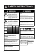
SAFETY INSTRUCTIONS WARNING Do not open the equipment. Hazardous voltage which can cause electrical shock, burn or serious injury exists inside the equipment. Only qualified personnel should work inside the equipment. Do not approach the antenna closer than 0.9 m (MPE by FCC) when it is transmitting. The antenna emits radio waves which can be harmful to the human body. WARNING Do not operate the equipment with wet hands. Electrical shock can result. Keep heater away from equipment.
Important Notices • No part of this manual may be copied or reproduced without written permission. • If this manual is lost or worn, contact your dealer about replacement. • The contents of this manual and equipment specifications are subject to change without notice. • The example screens (or illustrations) shown in this manual may not match the screens you see on your display. The screen you see depends on your system configuration and equipment settings.
TABLE OF CONTENTS FOREWORD ....................................................................................................... vii SYSTEM CONFIGURATION................................................................................ ix SPECIFICATIONS........................................................................................... SP-1 1. OPERATIONAL OVERVIEW 1.1 Controls Keys and LCD Indication............................................................................. 1-1 1.1.1 Front panel...
TABLE OF CONTENTS 3. DSC OPERATION FOR NON-DISTRESS CASES 3.1 Coast or Ship Call ....................................................................................................... 3-1 3.1.1 Sending a coast or ship call.............................................................................. 3-2 3.1.2 Receiving acknowledgement of coast or ship call ............................................ 3-4 3.1.3 Receiving a coast or ship call .................................................................
TABLE OF CONTENTS 5. SYSTEM SETUP 5.1 5.2 5.3 5.4 Displaying Self ID ...................................................................................................... 5-1 Displaying Group ID List.......................................................................................... 5-1 Naming Intercom....................................................................................................... 5-2 Displaying Program Version .................................................................
FOREWORD A Word to FM-8800D/FM-8800S Owners Congratulations on your choice of the FURUNO FM-8800D/FM-8800S VHF Radiotelephone. We are confident you will see why the FURUNO name has become synonymous with quality and reliability. For over 50 years FURUNO Electric Company has enjoyed an enviable reputation for quality marine electronics equipment. This dedication to excellence is furthered by our extensive global network of agents and dealers.
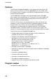
FOREWORD Features The FURUNO FM-8800D/FM-8800S is a cost-effective all-in-one marine VHF radio system consisting of a 25 W VHF radiotelephone, a DSC modem, and a CH 70 watch receiver. It complies with GMDSS carriage requirements for safety and general communications. The FM-8800D offers full-duplex voice communications and the FM-8800S offers simplex voice communication on ITU channels in the marine mobile VHF band.
SYSTEM CONFIGURATION The FM-8800D/FM-8800S is a highly advanced 25 W VHF transceiver with DSC terminal. It is designed to satisfy the stringent requirements of marine communications, and complies with GMDSS carriage requirements for safety and general communications.
SYSTEM CONFIGURATION This page is intentionally left blank.
SPECIFICATIONS OF MARINE VHF RADIOTELEPHONE FM-8800D/FM-8800S 1. GENERAL (1) Number of Channels INTL: 57 USA: 55 (57)* Weather: 10 Canada: 55 (57)* INLND-WA: 55 (57)* Private: 20 *: CH75&76 can be included MEMORY CH: 50 for some countries. Within ±1.5 kHz FM-8800S: Simplex/Semi-duplex FM-8800D: Simplex/Full-duplex 16K0G3E (Voice) 16K0G2B (DSC) 50 ohms (2) Frequency Stability (3) Communication System (4) Class of Emission (5) Antenna Impedance 2.
5. CH70 WATCH RECEIVER (1) Receiving Frequency 156.525 MHz (2) Sensitivity Symbol error rate: Less than 1% (at 0 dBµV) (3) Conducted Spurious Emission Less than 2 nW 6. POWER REQUIREMENTS (1) Power Supply (2) Power Consumption 24 VDC (-10%/+30%) FM-8800S Waiting 0.5 A Receive 1.6 A at 4 W audio output Transmit 1.6 A at 1 W output, 4.7 A at 25 W output FM-8800D Waiting 0.5 A Receive 1.6 A at 4 W audio output Transmit 2 A at 1 W output, 6 A at 25 W output DUP Transmit 3.6 A at 1 W output, 7.
1. OPERATIONAL OVERVIEW The FM-8800D/FM-8800S system consists of a transceiver block and two antennas. The transceiver block contains a VHF transmitter, receiver, and channel 70 watch receiver module. FM-8800D additionally provides a duplexer block. All operations are controlled on its front panel. 1.1 Controls Keys and LCD Indication 1.1.1 Front panel Loudspeaker Transmits the distress alert. Press this button three seconds continuously. LCD Keep pressed for 4 s in case of DISTRESS.
1. OPERATIONAL OVERVIEW 1.1.2 Controls The functions of keys of the transceiver unit and the remote station are almost the same. The table below shows the controls and keys for the transceiver unit. Control Function CHANNEL • Selects a channel. (PUSH TO ENTER) • Moves the cursor in menu opened. • Registers selected item when pressed. • Mutes the receiver when no signal is present on the channel selected. SQUELCH • AUTO position automatically reduces white noise.
1. OPERATIONAL OVERVIEW 1 • Enters 1, ., ,, ”, :, ;, -, +, *, #, entry mode. , (, ), !, $, &, / character at • Turns the loudspeaker on or off. Pressing the SHIFT and then this key turns loudspeaker on or off. In the off state, the loudspeaker icon appears. However, the key click actives and the alarm sounds when a distress or urgent call is activated. 2 ABC 3 TEST • Enters alphanumeric data (2, A, B, C, a, b, c). • Adjusts panel illumination when proceeded by the SHIFT key.
1. OPERATIONAL OVERVIEW • Enters “0”. 0 HI/LO • Changes the output power high (25 W) or low (1 W). However, the following channels are always 1 W. INTL mode: CH15, CH17, CH75, CH76 USA mode: CH13, CH17, CH67 ▲ * SHIFT ▼ LOG # CH16 FILE MENU ENT • Press to activate secondary function. • Moves the screen to previous item. • Moves cursor backward for editor field. • Displays transmitting/receiving messages. • Moves the screen to next item. • Moves cursor forward for editor field.
1. OPERATIONAL OVERVIEW 1.1.3 Indications on the LCD Below are all the indications which appear on the standby display on the transceiver unit. INTL 1 SHIFT 4 Hi 5 Rx 7 6 DUP 14 AUTO ACK * LAT: 34 °45' N LON: 135° 45' E 8 116 SCAN 10WATCH 9 2 CH70 * 10:45 UTC AUTO 13 11 3 12 Standby display on the transceiver unit Reference no. 1 2 3 4 5 6 7 8 9 10 11 12 13 14 Meaning Displays the channel mode.
1. OPERATIONAL OVERVIEW Below are the indications which appear on the standby display on the remote handset. Hi Rx SCAN DUP SHIFT T INTL 03 WATCH CH70** LAT: 12°34' N LON: 123° 45' E 12:34 UTC AUTO MANUAL ACK** 3* GPS ERROR T at the left-hand screen, right-hand screen appears. If you press If you press at the right-hand screen, the left-hand screen appears immediately. The indications are the same as those on of the transceiver unit. The *- marked number is the terminal number of the remote station.
1.
1. OPERATIONAL OVERVIEW 1.2.3 Adjusting volume of loudspeaker The VOLUME control adjusts the volume of the loudspeaker. 1.2.4 Adjusting squelch The SQUELCH control adjusts the squelch threshold level. Adjust it so that white noise heard in the loudspeaker just fades out. Perform this operation when no traffic is being received. AUTO squelch automatically reduces white noise. Usually select the AUTO position. Avoid turning the squelch too far clockwise — you may miss a long distance communication.
1. OPERATIONAL OVERVIEW 1.2.8 Quick selection of CH16 Press the CH16 key to select CH16, the International Calling and Safety Channel. The use is limited to distress, safety and calling. The transmission on CH16 (156.800 MHz) should be limited to within 1 minute except for distress calling. Avoid calling on CH16 for purposes other than distress, urgency and very brief safety communications when another calling channel is available. 1.2.
1. OPERATIONAL OVERVIEW 1.3 DSC Operational Overview Digital Selective Calling (DSC) is the global calling system adopted by the ITU-R and IMO for selective calling of coast station and ship radio stations. The DSC system is used for both safety and routine calling. The GMDSS requires the use of DSC for distress alerting and safety calls. 1.3.1 LED warnings The LED below the DISTRESS key lights continuously when the distress signal is transmitted.
1. OPERATIONAL OVERVIEW Preparing and transmitting DSC messages There are two methods by which you can prepare and transmit DSC messages, and they are shown below. ● Preparing message for immediate transmission 1. Press the CALL key at the standby display. 2. Select the call type. 3. Select other party (ID) if necessary. 4. Select the communications category. 5. Select the communications channel. 6. Press the CALL key more than three seconds.
1. OPERATIONAL OVERVIEW 1.4 Priority If one or more remote stations are installed, the transceiver unit (main unit) has the highest priority. You can interrupt remote station operation at any time with the handset of the main unit. When you hook off the handset of the main unit, “OCCUPIED FM8800” (default. This may be change. See section 5.3) is indicated on all remote stations. Each remote station has its own priority. The remote station ID (1-4) indicates its priority.
2. DSC DISTRESS COMMUNICATION 2.1 Distress Alert Transmission from the DISTRESS Key If a distress situation occurs, do as follows: 1. Open the DISTRESS key cover and press the DISTRESS key more than three seconds. The alarm sounds and the red lamp in the key blinks. The lamp will light steadily three seconds later and at the same time the distress alert is transmitted for three seconds. The screen changes as follows.
2. DSC DISTRESS COMMUNICATION 3) The screen changes to “distress acknowledge (DIST ACK) waiting” display. In this condition, distress communication with CH16 may be possible. ** Compose Message ** CALL TYPE: DISTRESS NATURE: UNDESIGNATED POS : 12 ° 34’N 123 ° 45’E AT : 12 : 34 Waiting for distress acknowledgement. CH16 Now available. TIME TO GO : 4M 12S 4) When the DIST ACK is received, Distress acknowledge received.
2. DSC DISTRESS COMMUNICATION 3. Press the ENT key. The standby display with CH16 and Hi appears. 4. Provide the following information to the coast station, using a handset on the transceiver unit or remote stations (if connected): Distress communication (1) Press the PTT switch and speak slowly and distinctly, “MAYDAY, MAYDAY, MAYDAY,” pronounced as the French expression “m’aider.” (2) This is; "the name of your vessel and call sign" three times.
2. DSC DISTRESS COMMUNICATION 2. Rotate the channel knob to choose the nature of distress. On the remote handset, press the up or down arrow key. S Sinking UNDESIGNATED Disabled & Adr Fire Abandoning Flooding Piracy Collision Man over board Grounding T Listing 3. Press the ENT key. The screen changes as follows.
2. DSC DISTRESS COMMUNICATION 2.3 Distress Alert Transmission from CALL Key You can transmit the distress alert with nature of distress by using CALL key. 1. Press the CALL key. ** Compose Message ** CALL TYPE : COAST CALL TO : COAST AAA COAST ID : 003456789 ROUTINE TCmd1 : SIMPLEX TP TCmd2 : NO INFO CH : 12 Transceiver unit screen * Compose message * CALL TYPE : COAST CALL T Remote handset screen 2. Press the ENT key to show the call type selection window.
2. DSC DISTRESS COMMUNICATION 5. Rotate the CH knob (or press up / down arrow key) to choose nature of distress and press the ENT key. ** Compose Message ** CALL TYPE : DISTRESS NATURE : Abandoning POS : 12 ° 34’N 123 ° 45’E AT : 12 : 34 SIMP TP 6. Press the ENT key to show the position setup window. INPUT TYPE : AUTO LAT : 34 ° 41’N LON : 134 ° 30’E TIME : 08 : 00 If a position fixing device is not connected, press the ENT key, choose Manual and enter your position.
2. DSC DISTRESS COMMUNICATION 2.5 Receiving Distress Alert from Other Vessel, Transmitting DIST ACK Signal In no case is a ship permitted to transmit a DSC distress relay call upon receipt of a DSC distress alert on VHF channel 70. Procedure when in area A1 1. When the FM-8800D/8800S receives a distress alert from another vessel, the ALARM LED (red) blinks and the FM-8800D/8800S sounds the distress alarm. 2. Silence the alarm by pressing the CANCEL key. 3.
2. DSC DISTRESS COMMUNICATION Flow chart for determining if you should/should not transmit DIST ACK signal DSC Distress alert received. Press [CANCEL] key to silence alarm. Listen on CH16 for 5 minutes. Did you receive acknowledge from CS and/or RCC? No Is distress traffic in progress? Yes Yes Is own vessel able to assist? No CS = Coast Station RCC = Rescue Co-ordination Center Enter details in log.
2. DSC DISTRESS COMMUNICATION Transmitting DIST ACK over CH16 Select VHF CH16 and transmit DIST ACK to vessel in distress. Reply received No reply Transmit DIST ACK to vessel in distress over DSC CH70. Communicate with vessel in distress. Relay the distress alert to a coast station over DSC. Follow the instructions of the coast station. Begin search and rescue operation for the vessel in distress.
2. DSC DISTRESS COMMUNICATION 1. Press the CANCEL or ENT key to silence the alarm. The following message appears. ** Received Message ** MAY10/’04 08:03 ECC : OK DISTRESS ID IN DIST : 123456789 NATURE : UNDESIGNATED POS : 12 ° 34’N 123 ° 45’E AT : 12 : 34 SIMP TP PRESS ENT TO ACK 2.
2. DSC DISTRESS COMMUNICATION 2.6 Sending Distress Relay on Behalf of a Ship in Distress When you should relay a distress alert You may relay a distress alert in the following conditions: 1) When the station in distress is not itself in a position to transmit the distress message, or 2) When the master or person responsible for the vessel not in distress, or the person responsible for the coast station, considers that further help is necessary.
2. DSC DISTRESS COMMUNICATION 4. Press the ENT key. ** Compose Message ** CALL TYPE : RELAY SEL COAST ID : 00 ID IN DIST : NO INFO TCmd : DISTRESS RELAY NATURE : UNDESIGNATED POS : 12 ° 34’N 123 ° 45’E AT : 12 : 34 SIMP TP 5. Press the ENT key again. The COAST ID entry window appears. 6. Key in a coast station ID with numeric keys and press the ENT key. 7. Press the ENT key again. The ID IN DIST entry window appears. 8. Key in the ID number of ship in distress with numeric keys and press the ENT key.
2. DSC DISTRESS COMMUNICATION 12. Press the CALL key more than three seconds to transmit the distress relay. ** Compose Message ** CALL TYPE : RELAY SEL COAST ID : 003456789 ID IN DIST : NO INFO TCmd : DISTRESS RELAY NATURE : UNDESIGNATED POS : 12 ° 34’N 123 ° 45’E AT : 12 : 34 SIMP TP When CALL key is pressed, this message appears and timer counts down. KEEP PRESSED FOR 3S The message will be transmitted and “Waiting for acknowledgement” will appear. 2.6.2 Sending distress relay to all ships 1.
2. DSC DISTRESS COMMUNICATION 4. Press the ENT key. ** Compose Message ** CALL TYPE : RELAY ALL ID IN DIST : NO INFO TCmd : DISTRESS RELAY NATURE : UNDESIGNATED POS : 12 ° 34’N 123 ° 45’E AT : 12 : 34 SIMP TP 5. Press the ENT key again. The ID IN DIST entry window appears. 6. Key in the ID number of ship in distress with numeric keys and press the ENT key. If you do not know the ID, simply press the ENT key without entering ID; NO INFO is displayed. 7.
2. DSC DISTRESS COMMUNICATION 10. Press the CALL key to transmit the call. ** Compose Message ** CALL TYPE : RELAY ALL ID IN DIST : NO INFO TCmd : DISTRESS RELAY NATURE : UNDESIGNATED POS : 12 ° 34’N 123 ° 45’E AT : 12 : 34 SIMP TP KEEP PRESSED FOR 3S When CALL key is pressed, this message appears and timer counts down. After the call is transmitted, the standby display appears. 2.7 Receiving Distress Relay 2.7.
2. DSC DISTRESS COMMUNICATION 2. Press the CANCEL key or ENT key to silence the alarm and the display changes as below. * Received Message * APR01/ 04 12 : 34 ECC : OK DISTRESS RELAY ALL FROM : 123456789 ID IN DIST : 234567890 TCmd : DISTRESS RELAY NATURE : UNDESIGNATED POS : 12 ° 34’N 123 ° 45’E AT : 12 : 34 SIMP TP PRESS ENT 3. Press the ENT key to return to the standby display with CH16. 4. Watch CH16. 2.7.
2. DSC DISTRESS COMMUNICATION 2. Press the CANCEL key to silence the alarm and the display changes as below. ** Received Message ** APR01/ 04 12 : 34 ECC : OK DISTRESS RELAY ALL FROM : 003456789 ID IN DIST : 123456789 TCmd : DISTRESS RELAY NATURE : UNDESIGNATED POS : 12 ° 34’N 123 ° 45’E AT : 12 : 34 SIMP TP PRESS ENT 3. Press the ENT key to return to the standby display with CH16. 4. Watch CH16.
2. DSC DISTRESS COMMUNICATION This page is intentionally left blank.
3. DSC OPERATION FOR NON-DISTRESS CASES 3.1 Coast or Ship Call The coast or ship call is for sending message to a specific coast or ship station. After transmitting message (called ACK RQ transmission), wait to receive the acknowledge back (ACK BQ) signal from the receiving station. You should receive it within five minutes.
3. DSC OPERATION FOR NON-DISTRESS CASES 3.1.1 Sending a coast or ship call 1. Press the CALL key. The display changes from the standby display to the COMPOSE MESSAGE screen and the CALL TYPE is displayed in reverse video. ** Compose Message ** CALL TYPE : COAST CALL TO : COAST AAA*1 COAST ID : 003456789 ROUTINE TCmd1 : SIMPLEX TP TCmd2 : NO INFO CH : 12 * Compose message * CALL TYPE : COAST CALL T *1: If the coast or ship ID is registered in FILE, the registered name is displayed.
3. DSC OPERATION FOR NON-DISTRESS CASES 9. Choose SIMPLEX TP, DUPLEX TP, DATA or FAX as appropriate followed by pressing the ENT key. If you chose SIMPLEX, DUPLEX or FAX, NO INFO appears in the Tcmd2 field. Go to step 12. If you chose DATA, go to the next step. 10. TCmd2 is selected; press the ENT key. V. V. V. V. T V. S V. 26 ter 21 22 22 bis 23 26 bis V. 27 ter V. 32 11. Choose the data type and press the ENT key. 12. Choose CH and press the ENT key. The following window appears.
3. DSC OPERATION FOR NON-DISTRESS CASES 3.1.2 Receiving acknowledgement of coast or ship call 1. After a coast or ship call is sent, the equipment waits for acknowledgement of the call, showing the display below. Waiting for acknowledgement. COAST ID : 003456789 ROUTINE TCmd1 : SIMPLEX TP TCmd2 : NO INFO CH : 12 TIME TO GO : 3M30 S The timer starts counting down the maximum time to wait for acknowledgement, five minutes. 2. One of the following three messages appears.
3. DSC OPERATION FOR NON-DISTRESS CASES Able acknowledge call received a) The audio alarm sounds; press the CANCEL key to silence it, and the display changes as below. ** Received Message ** APR01/ 04 12 : 34 ECC : OK COAST ACK FROM : 003456789 ROUTINE TCmd1 : SIMPLEX TP TCmd2 : NO INFO CH : 12 If a file is registered, its registered name is displayed instead of ID. PRESS ENT b) Press the ENT key to go to the standby display. The working channel is automatically set; you may start voice communications.
3. DSC OPERATION FOR NON-DISTRESS CASES Acknowledging the call automatically or manually by doing one of the following: 1) Send automatic acknowledge (ACK BQ) with comply status “ABLE.” See the procedure below. 2) Sending automatic acknowledge (ACK BQ) with comply status "UNABLE." See the procedure on page 3-7. 3) Manually acknowledging individual call with "ABLE." See the procedure on page 3-8. 4) Manually acknowledging a coast or ship call with "UNABLE.
3. DSC OPERATION FOR NON-DISTRESS CASES 2) Sending automatic acknowledge (ACK BQ) with comply status "UNABLE." 1. When the automatic acknowledge feature is active (AUTO ACK), the comply status is "UNABLE" and a coast or ship call is received, the display shown below appears, indicating that the auto acknowledge call with UNABLE (ACK BQ) has been sent. The alarm sounds and the ALARM LED blinks two minutes. Unable acknowledge transmitted. ROUTINE TCmd1 : UNABLE TCmd2 : BUSY CH : NO INFO CANCEL ALARM 2.
3. DSC OPERATION FOR NON-DISTRESS CASES 3) Manually acknowledging individual call with "ABLE." 1. When the equipment is set up with manual acknowledge (MANUAL ACK), the comply status is "ABLE" and a coast or ship call is received, the alarm sounds and the display looks like the one below. Individual request call received. FROM : 123456789 ROUTINE TCmd1 : SIMPLEX TP TCmd2 : NO INFO CH : 08 CANCEL ALARM 2. Press the CANCEL key to silence the alarm. The following display appears.
3. DSC OPERATION FOR NON-DISTRESS CASES 4. Choose ABLE and press the ENT key. The display changes as shown below. ** Send Message ** SHIP ACK TO : 123456789 ROUTINE TCmd1 : SIMPLEX TP TCmd2 : NO INFO CH : 08 PRESS CALL TO SEND 5. Press the CALL key more than three seconds to transmit the ACK BQ. The display changes to the standby display with a channel specified. 4) Manually acknowledging a coast or ship call with "UNABLE." 1.
3. DSC OPERATION FOR NON-DISTRESS CASES 3. To send the ACK BQ manually, press the ENT key. The pop-up window shown below is displayed. ABLE UNABLE 4. Choose UNABLE and press the ENT key. The following pop-up screen appears. NO REASON BUSY EQUIP DISBLD MODE UNAVAIL CH UNAVAIL 5. Press the ENT key. ** Send Message ** SHIP ACK TO : 123456789 ROUTINE TCmd1 : UNABLE TCmd2 : NO REASON CH : NO INFO PRESS CALL TO SEND 6. Press the CALL key more than three seconds to transmit the ACK BQ.
3. DSC OPERATION FOR NON-DISTRESS CASES 2. Press the ENT key to open the call type list. G COAST CALL SHIP CALL GROUP CALL PSTN CALL ALL SHIPS AREA CALL POSITION F POLLING NEUTRAL MEDICAL RELAY ALL RELAY SEL DISTRESS 3. Rotate the CH knob (or press up / down arrow key) to choose GROUP CALL and press the ENT key. 4. GROUP ID is selected; press the ENT key. 5. Key in a group ID and press the ENT key. 6. ROUTINE is selected; press the ENT key. ROUTINE BUSINESS SAFETY URGENCY DISTRESS 7.
3. DSC OPERATION FOR NON-DISTRESS CASES 13. Choose SELECT CH or NO INFO as appropriate followed by pressing the ENT key. If you chose SELECT CH, the following channel list appears. (The example shown is the international, duplex channel list.) Rotate the CH knob (or press up / down arrow key) to choose a channel you wish to communicate and press the ENT key. DUP CHANNEL 01 02 03 04 05 07 18 19 20 21 22 23 24 25 26 27 28 60 61 62 63 64 65 66 78 79 80 81 82 83 84 85 86 14.
3. DSC OPERATION FOR NON-DISTRESS CASES 3.3 PSTN Call The PSTN call allows the making and receiving of telephone calls over public switched telephone networks. To use the PSTN call feature, use a handset which has a HOOK ON/OFF function. The standard supply handset has this feature. 3.3.1 Sending a PSTN call 1. Press the CALL key. The display changes from standby display to the COMPOSE MESSAGE screen and the CALL TYPE is displayed in reverse video. 2. Press the ENT key to open the call type list.
3. DSC OPERATION FOR NON-DISTRESS CASES If a response from the coast station is received within five seconds, transmit PSTN CALL (EOS) signal and then carrier frequency during two seconds. Then your phone rings. Press the CANCEL key to stop the calling sound and change to standby display. Hook off and communicate with other party. Note: If using a hand-microphone, pressing the CANCEL key is equal to off-hook. 3.3.2 PSTN call disconnection (ship disconnects line) 1.
3. DSC OPERATION FOR NON-DISTRESS CASES 3.3.3 PSTN call disconnection (coast station disconnects line) 1. The PSTN line is disconnected by the coast station when it finds no evidence of communications or the land subscriber hangs up. The coast station then sends charge information as below. PSTN end of call received. FROM : 003456789 TCmd1 : END CALL TCmd2 : NO INFO TEL : 1234567890123456 CHARGE TIME : 00h06m18s PRESS ENT 3.3.4 Receiving a PSTN call 1.
3. DSC OPERATION FOR NON-DISTRESS CASES 3.4 All Ships Call When an urgent but not life-endangering situation arises on your ship, for example, engine trouble, send an all ships call to request assistance. After sending the call, you can communicate by voice over the radiotelephone. Do the following before beginning actual communications: URGENCY priority: Say PAN three times followed by your call sign. SAFETY priority: Say SECURITE three times followed by your call sign. Coast Station Own Ship 3.4.
3. DSC OPERATION FOR NON-DISTRESS CASES 7. Choose SIMPLEX TP, DUPLEX TP, DATA or FAX as appropriate followed by pressing the ENT key. If you chose SIMPLEX, DUPLEX, or FAX, the NO INFO appears in the Tcmd2 field. Go to the step 10. If you chose DATA, go to the next step. 8. TCmd2 is selected; press the ENT key. V. V. V. V. T V. S V. 26 ter 21 22 22 bis 23 26 bis V. 27 ter V. 32 9. Choose the data type and press the ENT key. 10. Choose CH and press the ENT key. The following window appears.
3. DSC OPERATION FOR NON-DISTRESS CASES 3.4.2 Receiving an all ships call In case of ON HOOK 1. When an all ships call is received, the audio alarm sounds and the display looks something like the one shown below. All ships call received. FROM : 123456789 SAFETY TCmd1 : SIMPLEX TP TCmd2 : NO INFO CH : 16 CANCEL ALARM 2. Press the CANCEL or ENT key to silence the alarm. The display changes as follows.
3. DSC OPERATION FOR NON-DISTRESS CASES 3.5 Geographical Area Call The geographical area call is for sending a call to all ships within the area you designate in your geographical area call. In the figure below, for example, the call will be sent to all ships within 24-34°N, 135-140°W. Reference point (For example, 34°N 140°W) 34°N 10° 24°N 140°W 3.5.1 5° 135°W Sending a geographical area call 1. Press the CALL key.
3. DSC OPERATION FOR NON-DISTRESS CASES 8. TCmd1 is selected; press the ENT key. 9. Choose SIMPLEX TP, DUPLEX TP, DATA or FAX as appropriate followed by pressing the ENT key. If you chose SIMPLEX, DUPLEX, or FAX, NO INFO appears in the Tcmd2 field. Go to step 12. If you chose DATA, go to the next step. 10. TCmd2 is selected; press the ENT key. V. V. V. V. T V. S V. 26 ter 21 22 22 bis 23 26 bis V. 27 ter V. 32 11. Choose the data type and press the ENT key. 12.
3. DSC OPERATION FOR NON-DISTRESS CASES 3.5.2 Receiving a geographical area call 1. When a geographical area call is received, the alarm sounds and the ALARM LED blinks two minutes. Geographical area call received. FROM : 123456789 AREA : 12 ° N 123 ° E ↓ 01 ° → 01 ° ROUTINE TCmd1 : SIMPLEX TP TCmd2 : NO INFO CH : 10 CANCEL ALARM 2. Press the CANCEL key to silence the alarm. The following display appears.
3. DSC OPERATION FOR NON-DISTRESS CASES 3.6 Position Call There are two types of position calls: other station requires your ship's position and your ship requests position of another ship. Finding position of other station Sending own ship's position to other station Other Station Own Station 3.6.1 Position call: requesting other ship's position 1. Press the CALL key. The display changes from standby display to the COMPOSE MESSAGE screen and the CALL TYPE is displayed in reverse video. 2.
3. DSC OPERATION FOR NON-DISTRESS CASES 8. Press the CALL key more than three seconds to transmit position request. The following display appears. The timer counts down until a response is received. Waiting for acknowledgement. SHIP ID : 123456789 ROUTINE TCmd1 : POSITION REQUEST TCmd2 : NO INFO If a file is registered, its registration name is displayed. If not, this field is blank. TIME TO GO : 3M30 S 9. When an acknowledge call is received, the following display appears and the audio alarm sounds.
3. DSC OPERATION FOR NON-DISTRESS CASES 3.6.2 Position call: other ship requests your position You may turn automatic acknowledge of position request on or off with POSITION CALL in the system setup menu. For further details, see page 4-3. Automatic reply 1. When another ship requests your position, the status of the 5 ACK key is AUTO ACK and the setting of POSITION CALL on the system setup menu is ON, the FM-8800D/S transmits own position data, showing the display below. Position auto ack transmitted.
3. DSC OPERATION FOR NON-DISTRESS CASES 2. Press the CANCEL key to silence the alarm. ** Received Message ** APR01/ 04 12 : 34 POSITION CALL FROM : 123456789 ROUTINE TCmd1 : POSITION TCmd2 : NO INFO ECC : OK PRESS ENT TO ACK. 3. To send your position manually, press the ENT key. The following pop-up menu appears. ANSWER NO ANSWER 4. Choose ANSWER by the CH knob and press the CALL key to send your position data. Then, the standby display appears.
3. DSC OPERATION FOR NON-DISTRESS CASES 3. Rotate the CH knob (or press up / down arrow key) to choose POLLING and press the ENT key. ** Compose Message ** CALL TYPE : POLLING SHIP ID : ROUTINE TCmd1 : POLLING TCmd2 : NO INFO 4. SHIP ID is selected; press the ENT key. 5. Key in a station ID with the numeric keys and press the ENT key. 6. ROUTINE is selected; press the ENT key. ROUTINE BUSINESS SAFETY URGENCY DISTRESS 7.
3. DSC OPERATION FOR NON-DISTRESS CASES 9-2. When "No response! Try calling again?" is displayed, do one of the following: Re-send call: Push the ENT key followed by the CALL key. Cancel call: Press the CANCEL key to return to the standby display. 3.7.2 Receiving a polling call Automatic reply 1.
3. DSC OPERATION FOR NON-DISTRESS CASES Manual reply 1. When a polling request call is received and the setting of POLLING CALL on the system setup menu is OFF, the display changes as shown in the illustration below and the audio alarm sounds. Position request call received. FROM : 123456789 ROUTINE TCmd1 : POLLING TCmd2 : NO INFO CANCEL ALARM 2. Press the CANCEL key to silence the alarm. The display changes as below.
3. DSC OPERATION FOR NON-DISTRESS CASES 3.8 Neutral Craft Call The neutral craft call, which contains own ship position and ID, informs all ships that your ship is not a participant in armed conflict. Send the call BEFORE entering an area of armed conflict. 3.8.1 Sending a neutral craft call 1. Press the CALL key. The display changes from the standby display to the COMPOSE MESSAGE screen and the CALL TYPE is displayed in reverse video. 2. Press the ENT key to open the call type list. 3.
3. DSC OPERATION FOR NON-DISTRESS CASES 2. Press the CANCEL or ENT key. The audible alarm is silenced and the display changes as below. ** Received Message ** APR01/ 04 12 : 34 ECC : OK NEUTRAL CALL FROM : 123456789 SAFETY TCmd1 : SIMPLEX TP TCmd2 : NEUTRAL CRAFT CH : 16 PRESS ENT TO CHANGE CH 3. Press the ENT key. The display changes to the standby display, indicating CH16. 3.
3. DSC OPERATION FOR NON-DISTRESS CASES 3.9.2 Receiving a medical transport call 1. When a medical call is received, the alarm sounds and the display changes as below. Medical call received. FROM : 123456789 URGENCY TCmd1 : SIMPLEX TP TCmd2 : MEDICAL CH : 16 CANCEL ALARM 2. Press the CANCEL or ENT key. The audible alarm stops and the display changes as below.
3. DSC OPERATION FOR NON-DISTRESS CASES 3.10 Log File Three log files are provided for storage of calls: received ordinary log, received distress log and transmitted log. Each log file stores 50 calls, on a first-in, first-out basis. This means that the latest call is saved as log no.1 and the log no. of all previous calls in that log increments by one. When the storage capacity is exceeded, the oldest call is deleted to make room for the latest. A letter mark shows unread or unacknowledged calls.
3. DSC OPERATION FOR NON-DISTRESS CASES 4. Press the ENT key to open the message. Below is a sample message. ** Received Message ** APR 10/’04 18:30 ECC : OK SHIP CALL FROM : 123456789 ROUTINE TCmd1 : SIMPLEX TP TCmd2 : NO INFO CH : 16 T DELETE T ANSWER For a received message which requires a reply, ANSWER is displayed (for 4.5 minutes). To reply choose it and press the ENT key. 5. Press ▲ or ▼ key to open previous or next page on the log. 6.
3. DSC OPERATION FOR NON-DISTRESS CASES This page is intentionally left blank.
4. BASIC SETUP 4.1 Alarm Setup This section provides the procedures for setting up various alarms. The alarm menu enables/disables internal and external alarms. Note that the Distress/Urgency alarm cannot be disabled. Old position alarm in manual position entry mode This alerts the operator when manually entered position data is older by the number of hours or minutes set. 1. Press the MENU key.
4. BASIC SETUP To set type of alarm to output 1. Rotate the CH knob (or press up / down arrow key) to choose EXT ALARM from the ALARM MENU and press the ENT key. The following setting window appears. DIST/URG : ON SAFETY : OFF ROUTINE : ON Always ON 2. Rotate the CH knob (or press up / down arrow key) to choose an appropriate option. Alarm is output to external device. DSTRS/URG: Distress or urgency call output upon receipt. SAFETY: Safety call output upon receipt.
4. BASIC SETUP 4.2 Auto ACK Setup The Auto Ack Menu enables/disables automatic acknowledgement of ship, coast, position and polling calls. Comply status Set of [5 ACQ] AUTO ACK MANUAL ACK ABLE UNABLE Can send acknowledge automatically. Can send acknowledge manually Can send UNABLE automatically. Can send UNABLE manually. To set COMPLY TYPE 1. Press the MENU key. 2. Rotate the CH knob (or press up / down arrow key) to choose AUTO ACK and press the ENT key. The following menu appears.
4. BASIC SETUP To set reason for unable If you have chosen UNABLE as the COMPLY STATUS, set the reason as follows: 1. Rotate the CH knob (or press up / down arrow key) to choose UNABLE REASON from the AUTO ACK MENU and press the ENT key. The following menu appears. NO REASON BUSY EQUIP DISBLD MODE UNAVAIL CH UNAVAIL 2. Rotate the CH knob (or press up / down arrow key) to choose a reason for UNABLE. 3. Press the ENT key. Note: This menu is the same as manual acknowledgement.
4. BASIC SETUP 4.3 Erasing Logs Erasing received ordinary log 1. Press the MENU key. 2. Rotate the CH knob (or press up / down arrow key) to choose the ERASE LOG and press the ENT key. The following window appears. *** ERASE LOG MENU *** RCVD ORDINARY RCVD DISTRESS TRANSMITTED 3. RCVD ORDINARY is selected; press the ENT key to erase the received ordinary log. 4. Choose YES and press the ENT key to erase the received ordinary log. Erasing received distress log 1. Press the MENU key. 2.
4. BASIC SETUP 4.4 Memory Channel Setup You can save up to 50 channels as follows. 1. Press the MENU key. 2. Rotate the CH knob (or press up / down arrow key) to choose MEMORY CHANNEL and press the ENT key. * Memory Channel 1/7* 01 CH-02 : CH-03 : CH-04 : CH-05 : CH-06 : CH-07 : CH-T 08 : CH-- --------------------------------------------------------- 3. Rotate the CH knob (or press up / down arrow key) to choose a vacant CH number and press the ENT key.
4. BASIC SETUP 4.5 Message File Entry In this section you will learn how to prepare and store ship, coast, PSTN, group, and area calls for future transmission. 100 calls can be stored. 1. At the standby display, press the MENU key to open the SETUP MENU. **** SETUP MENU **** ALARM AUTO ACK ERASE LOG MEMORY CHANNEL T MESSAGE FILE ENTRY 2. Rotate the CH knob (or press up / down arrow key) to choose MESSAGE FILE ENTRY and press the ENT key. * MESSAGE FILE 1/13 * 1: 2: 3: 4: 5: 6: 7: T 8: 3.
4. BASIC SETUP 4. Rotate the CH knob to choose the call type and press the ENT key. One of the following display appears depending on the call type selected above.
4. BASIC SETUP 5. Press the ENT key and key in each ID or AREA followed by the ENT key. To enter area 1: N/E 2: S/W -- ° N --- ° E ↓ -- ° → -- ° a) Enter latitude (degrees) and 1 for north or 2 for south of reference point. b) Enter longitude (degrees) and 1 for east or 2 for west. c) Enter southerly degrees of area. d) Enter easterly degrees of area. e) Press the ENT key. 6. TCmd1 is selected; press the ENT key. 7.
4. BASIC SETUP 12. Choose a channel with the CH knob (or up / down arrow key) and press the ENT key. 13. Press the ENT key to open the name entry window. 14. Enter a name with the alphanumeric keys. To change a digit, rotate the CH knob. Press the ENT key. '( ) '( !" #$ # !% && 15. REGIST is selected; press the ENT key to register.
4. BASIC SETUP Position Setup This is where you enter your position, automatically or manually. 1. Press the MENU key at the standby display. 2. Rotate the CH knob (or press up / down arrow key) to choose POSITION from the second page of the main menu. **** SETUP MENU **** T 4.6 POSITION PRINT OUT VOLUME SYSTEM 3. Press the ENT key. The following menu appears. INPUT TYPE: AUTO LAT : -- ° --’LON : --- ° --’TIME : -- : -4. INPUT TYPE is selected; press the ENT key. The following setting window appears.
4. BASIC SETUP 4.7 Print Out Setup The PRINT MENU enables/disables automatic printing of all transmitted and received calls and the results of the daily test. 1. Press the MENU key at the standby display to open menu. 2. Rotate the CH knob (or press up / down arrow key) to choose PRINT OUT from the second page of the main menu and press the ENT key. **** PRINT MENU **** XMTD CALL MANUAL RCVD CALL MANUAL DAILY TEST MANUAL 3.
4. BASIC SETUP Volume Setup The VOLUME menu enables/disables key beep (acknowledges correct key input) and adjusts the volume of the earpiece, intercom and off-hook loudspeaker. 1. Press the MENU key at the standby display. 2. Rotate the CH knob (or press up / down arrow key) to choose VOLUME and press the ENT key. **** VOLUME MENU **** KEY CLICK EARPIECE LEVEL INTERCOM VOLUME OFF HOOK SPKR 8 9 8 ON Follow the appropriate procedure to adjust volume of desired item. Key click 1.
4. BASIC SETUP Intercom volume 1. Choose INTERCOM VOLUME and press the ENT key. INTERCOM SETUP LEVEL (1-16) < < 8 EXT: ENT 2. Rotate the CH knob (or press up / down arrow key) to set the intercom volume level. The setting range is 1 to 16. 3. Press the ENT key. Off-hook loudspeaker You can set the loudspeaker(s) (internal and external) on or off, according to off-hook condition. 1. Choose OFFHOOK SPKR and press the ENT key. 2. Choose ON or OFF and press the ENT key.
5. SYSTEM SETUP 5.1 Displaying Self ID 1. Press the MENU key. ALARM AUTO ACK ERASE LOG MEMORY CHANNEL T MESSAGE FILE ENTRY **** SETUP MENU **** T **** SETUP MENU **** POSITION PRINT OUT VOLUME TEST SYSTEM 2. Rotate the CH knob (or press up / down arrow key) to choose SYSTEM from page 2 of the menu and press the ENT key. The following window appears. The self ID is displayed on the first line.
5. SYSTEM SETUP 5.3 Naming Intercom 1. Press the MENU key. **** SETUP MENU **** **** SETUP MENU **** ALARM AUTO ACK ERASE LOG MEMORY CHANNEL T MESSAGE FILE ENTRY POSITION PRINT OUT VOLUME TEST SYSTEM T 2. Rotate the CH knob (or press up / down arrow key) to choose SYSTEM from page 2 of the menu and press the ENT key. The following window appears. * SYSTEM SETUP MENU * SELF ID --------------------GROUP ID LIST INTERCOM NAMING PROGRAM VERSION 3.
5. SYSTEM SETUP Displaying Program Version 1. Press the MENU key. **** SETUP MENU **** ALARM AUTO ACK ERASE LOG MEMORY CHANNEL T MESSAGE FILE ENTRY **** SETUP MENU **** T 5.4 POSITION PRINT OUT VOLUME TEST SYSTEM 2. Rotate the CH knob to choose SYSTEM and press the ENT key. The following selection window appears. * SYSTEM SETUP MENU * SELF ID --------------------GROUP ID LIST INTERCOM NAMING PROGRAM VERSION 3.
5. SYSTEM SETUP This page is intentionally left blank.
6. MAINTENANCE & TROUBLESHOOTING WARNING Do not open the equipment. Hazardous voltage which can cause electrical shock, burn or serious injury exists inside the equipment. Do not work inside the equipment unless familiar with electrical circuits. 6.1 Maintenance Periodic checks 1) 2) 3) 4) 6.2 Check that each connector is firmly connected. Clean corroded or soiled connectors. Check coaxial cable for damage. If damaged, replace. Check that bolts fixing the antenna are firmly tightened.
6. MAINTENANCE & TROUBLESHOOTING 6.3 Daily Test Authorities require that the DSC be checked daily for proper operation to ensure that it will function properly in the event of distress. Execute the daily test as below. 1. At the standby display, press the SHIFT key and TEST key in that order. The following display appears for test. And distress alarm (visual and audible) occurs. Test in progress (Pop-up display appears momentarily.
6. MAINTENANCE & TROUBLESHOOTING 6.4 Error Message The table below shows all the error messages which may appear. Error message Meaning PLL1 Unlock PLL circuit on the TX/RX pcb 05P0774 has unlocked. PLL2 Unlock PLL circuit on the DUP RX pcb 05P0777 has unlocked (only FM-8800D). ANT ERROR The antenna is abnormal. In this condition, if the transmission continues more than five seconds, the output power is reduced to approximately 10W.
6.
APPENDIX Menu Tree Bold: Default [MENU] POSITION OLDER EXT ALARM ALARM 4H/3H/2H/1H/0.
APPENDIX 1 [CALL] COAST CALL SHIP CALL GROUP CALL PSTN CALL ALL SHIPS AREA CALL POSITION 1 AP-2 COAST ID ROUTINE BUSINESS SAFETY URGENCY DISTRESS TCmd1 SIMPLEX TP DUPLEX TP DATA FAX NO INFO TCmd2 CH SELECT CH / NO INFO SHIP ID ROUTINE BUSINESS SAFETY URGENCY DISTRESS TCmd1 SIMPLEX TP DUPLEX TP DATA FAX NO INFO TCmd2 CH SELECT CH / NO INFO GROUP ID ROUTINE BUSINESS SAFETY URGENCY DISTRESS TCmd1 SIMPLEX TP DUPLEX TP DATA FAX NO INFO TCmd2 SELECT CH / NO INFO CH COAST ID TCmd1 SIMPLEX TP DUPLEX TP
APPENDIX Marine VHF Channel Lists 1) International Channels CH 01 02 03 04 05 06 07 08 09 10 11 12 13 14 TX MHz 156.050 156.100 156.150 156.200 156.250 156.300 156.350 156.400 156.450 156.500 156.550 156.600 156.650 156.700 RX MHz 160.650 160.700 160.750 160.800 160.850 156.300 160.950 156.400 156.450 156.500 156.550 156.600 156.650 156.700 15 156.750 156.750 16 17 18 19 20 21 22 23 24 25 26 27 28 156.800 156.850 156.900 156.950 157.000 157.050 157.100 157.150 157.200 157.250 157.300 157.350 157.
APPENDIX 2) USA Channels TX MHz CH 01 156.050 02 03 04 05 156.250 06 156.300 07 156.350 08 09 10 11 12 13 14 15 16 17 18 19 20 21 22 23 24 25 26 27 28 156.400 156.450 156.500 156.550 156.600 156.650 156.700 156.800 156.850 156.900 156.950 157.000 157.050 157.100 157.150 157.200 157.250 157.300 157.350 157.400 RX MHz 156.050 156.250 156.300 156.350 Remark 156.400 156.450 156.500 156.550 156.600 156.650 156.700 156.750 156.800 156.850 Low PWR Low PWR 156.900 156.950 157.000 157.050 157.100 157.
APPENDIX 3) Canadian Channels CH 01 02 03 04 05 TX MHz 156.050 156.100 156.150 156.200 156.250 RX MHz 160.650 160.700 160.750 156.200 156.250 06 07 08 09 10 11 12 13 14 156.300 156.350 156.400 156.450 156.500 156.550 156.600 156.650 156.700 156.300 156.350 156.400 156.450 156.500 156.550 156.600 156.650 156.700 15 16 156.750 156.800 156.750 156.800 17 156.850 156.850 18 19 156.900 156.950 156.900 156.950 20 21 22 23 24 25 26 27 28 157.000 157.050 157.100 157.150 157.200 157.250 157.300 157.
APPENDIX 4) Inland waterways (INLND-WA) Channels CH 01 02 03 04 05 06 07 08 09 TX MHz 156.050 156.100 156.150 156.200 156.250 156.300 156.350 156.400 156.450 RX MHz 160.650 160.700 160.750 160.800 160.850 156.300 160.950 156.400 156.450 10 156.500 156.500 11 156.550 156.550 12 156.600 156.600 13 156.650 156.650 14 156.700 156.700 15 16 156.750 156.800 156.750 156.800 17 156.850 156.850 18 19 20 21 22 23 24 25 26 27 28 AP-6 156.900 156.950 157.000 157.050 157.100 157.150 157.
APPENDIX 5) Private Channels Note: Bold for FM-8800D duplex TX frequencies TX RX FM-8800S FM-8800D Simplex Sim/Dup FM-8800S FM-8800D Simplex Duplex CH NO(current) Simplex Semi-dup 155.000 155.000 159.600 180 155.025 155.025 159.625 181 155.050 155.050 159.650 182 155.075 155.075 159.675 183 155.100 155.100 159.700 184 155.125 155.125 159.725 185 155.150 155.150 159.750 186 155.175 155.175 159.775 187 155.200 155.200 159.800 188 155.225 155.225 159.
APPENDIX TX RX FM-8800S FM-8800D FM-8800S FM-8800D Simplex Sim/Dup Simplex Semi-dup Simplex Duplex 155.975 155.975 155.975 160.575 155.975 156.000 156.000 156.000 160.600 156.000 160.600 156.025 156.025 156.025 160.625 156.025 160.625 156.050 156.050 156.050 160.650 156.050 160.650 156.075 156.075 156.075 160.675 156.075 160.675 156.100 156.100 156.100 160.700 156.100 160.700 156.125 156.125 156.125 160.725 156.125 160.725 156.150 156.150 156.150 160.
APPENDIX TX RX FM-8800S FM-8800D FM-8800S FM-8800D Simplex Sim/Dup Simplex Semi-dup Simplex Duplex 156.975 156.975 156.975 161.575 156.975 161.575 157.000 157.000 157.000 161.600 157.000 161.600 157.025 157.025 157.025 161.625 157.025 161.625 157.050 157.050 157.050 161.650 157.050 161.650 157.075 157.075 157.075 161.675 157.075 161.675 157.100 157.100 157.100 161.700 157.100 161.700 157.125 157.125 157.125 161.725 157.125 161.725 157.150 157.150 157.
APPENDIX TX RX FM-8800S FM-8800D FM-8800S FM-8800D Simplex Sim/Dup Simplex Semi-dup Simplex 157.975 157.975 157.975 162.575 157.975 158.000 158.000 158.000 162.600 158.000 158.025 158.025 162.625 158.025 158.050 158.050 162.650 158.050 158.075 158.075 162.675 158.075 158.100 158.100 162.700 158.100 158.125 158.125 162.725 158.125 158.150 158.150 162.750 158.150 158.175 158.175 162.775 158.175 158.200 158.200 162.800 158.200 158.225 158.225 162.825 158.
APPENDIX TX RX FM-8800S FM-8800D Simplex Sim/Dup FM-8800S FM-8800D Duplex CH NO(current) Simplex Semi-dup Simplex 158.975 158.975 163.575 158.975 159.000 159.000 163.600 159.000 200 159.025 159.025 159.025 201 159.050 159.050 159.050 202 159.075 159.075 159.075 203 159.100 159.100 159.100 204 159.125 159.125 159.125 205 159.150 159.150 159.150 206 159.175 159.175 159.175 207 159.200 159.200 159.200 208 159.225 159.225 159.225 209 159.250 159.250 159.
APPENDIX TX RX FM-8800S FM-8800D Simplex Sim/Dup FM-8800S Simplex Semi-dup FM-8800D Simplex Duplex CH NO(current) Remark 159.975 159.975 159.975 239 160.000 160.000 160.000 240 160.025 160.025 160.025 241 160.050 160.050 160.050 242 160.075 160.075 160.075 243 160.100 160.100 160.100 244 160.125 160.125 160.125 245 160.150 160.150 160.150 246 160.175 160.175 160.175 247 160.200 160.200 160.200 248 160.225 160.225 160.225 249 160.250 160.250 160.
APPENDIX TX RX FM-8800S FM-8800D Simplex Sim/Dup FM-8800S Simplex Semi-dup FM-8800D Simplex Duplex CH NO(current) 160.975 160.975 160.975 159 161.000 161.000 161.000 160 161.025 161.025 161.025 161 161.050 161.050 161.050 162 161.075 161.075 161.075 163 161.100 161.100 161.100 164 161.125 161.125 161.125 165 161.150 161.150 161.150 166 161.175 161.175 161.175 167 161.200 161.200 161.200 168 161.225 161.225 161.225 169 161.250 161.250 161.250 170 161.
APPENDIX Digital Interface (IEC 61162-1 Edition 2) Input sentences GGA, GLL, RMC, ZDA, GNS Schematic diagram R70 10 05P0773 J2 TXD-H 7 TXD-C 8 RXD-H 9 RXD-C 10 Isolation Input impedance Max.
APPENDIX GGA - Global positioning system (GPS) fix data
APPENDIX GLL - Geographic position - latitude and longitude !"# $%& '"( )* $+ ,$ $% # - . / 0. %/ 1$ % 2 $34 %$ 5 26 !7*' 8$ $% %& 1$ % 2 $3. $%$ $ 9 . 9 ++ 3 % ' .
APPENDIX RMC - Recommemded minimum specific GPS/TRANSIT data $--RMC,hhmmss.ss,A,llll.lll,a,yyyyy.yyy,a,x.x,x.x,xxxxxx,x.
APPENDIX TLL – Target latitude and longitude $--TLL,xx,llll.lll,a,yyyyy.yyy,a,c--c,hhmmss.ss,a,a*hh | | | | | | | | | | | | | | | | | | | +--------- 8 | | | | | | | | +----------- 7 | | | | | | | +------------- 6 | | | | | | +-------------------- 5 | | | | | +-------------------------- 4 | | | +-----+------------------------------ 3 | +----+------------------------------------------ 2 +----------------------------------------------------- 1 1. Target number 00 - 99 2. Latitude, N/S 3.
INDEX A L Able acknowledge call.................................3-5 ACK BQ .......................................................3-7 Alarm setup..................................................4-1 All ships call...............................................3-16 Audio alarms................................................1-6 Auto ACK setup ...........................................4-3 Automatic acknowledge .....................1-11, 3-7 LCD..............................................................
INDEX U V Unable acknowledge call.............................3-5 Volume.........................................................1-8 Volume setup.............................................