Back 15" MULTI-COLOR HIGH-PERFORMANCE SHIPBORNE RADAR AND ARPA FR-1500 MARK-3 SERIES
Your Local Agent/Dealer 9-52 Ashihara-cho, Nishinomiya, Japan Telephone : 0798-65-2111 Telefax : 0798-65-4200 All rights reserved. Printed in Japan FIRST EDITION : OCT. 1998 U PUB.No. OME-34500 ( HIMA ) FR-1500 MARK-3 SER. : NOV.
SAFETY INSTRUCTIONS DANGER Before turning on the radar/ARPA, make sure that there is not one near the antenna unit. Serious injury or even death may result if a rotating antenna strikes someone standing nearby. WARNING Radio frequency Radiation Hazard The radar antenna emits electromagnetic radio frequency (RF) energy, which can be harmful, particularly to your eyes.
For your safety: WARNING Do not open the equipment Hazardous voltage which can cause electrical shock exists inside the equipment. Only qualified personnel should work inside the equipment. Turn off the radar power switch before servicing the antenna unit. Post a warning sign near the switch indicating it should not be turned on while the antaean unit is being serviced. Prevent the potential risk of being struck by the rotating antenna and exposure to RF radiation hazard.
TABLE OF CONTENTS INTRODUCTION................................................................................................................................................ v Specifications of FR-1500 Mark-3 Series shipborne radar ....................................................................... viii 1 OPERATIONAL OVERVIEW.................................................................................................................... 1.1 1.1 Turning on the Power ..................................
1.52 Real Time Heading Up .......................................................................................................................... 47 2 OPERATION OF AUTOMATIC TRACKING AID (ATA) ARP-17 ............................................................ 2.1 2.1 Introduction................................................................................................................................................ 1 2.2 Criteria of Tracking ......................................................
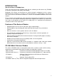
INTRODUCTION Word to the Owner of FURUNO Radar Thank you for purchasing this FURUNO radar. We are confident you will discover why FURUNO has become synonymous with quality and reliability. Dedicated in the design and manufacture of marine electronics equipment for half a century, FURUNO Electric Company has gained an unrivaled reputation as a world leader in the industry. This is the result of our technical excellence as well as our worldwide distribution and service network.
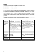
Models This series of radar and ARPA is available in the following models: FR-1505 MARK-3 FR-1510 MARK-3 X-band 6 kW X-band 12 kW FR-1525 MARK-3 X-band 25 kW All come with the EPA (Electronic Plotting Aid) fitted standard. An option is available to provide the full functionality of ATA (Automatic Tracking Aid). A Video Plotter (Chart Plotter), which provides Radar Map functions, and Performance Monitor are also optionally available.
When the gyrocompass or magnetic compass is not connected to IMO type radar, the functions mentioned below are inoperative. In this case, the HDG SNSR on the SET UP 2 menu of the Installation menu should be set to OFF. (See page 5-7 in the installation manual.) 1. Alert and indication for heading sensor do not appear on the screen and also the indication of HDG does not appear on the screen. 2. The PLOT on the main menu is not accessible. Therefore, the menus of EPA and ATA are not accessible. 3.
Specifications of FR-1500 Mark-3 Series shipborne radar ANTENNA RADIATORS 1. Type: Slotted waveguide array 2. Beamwidth: Radiator type: XN12AF XN20AF XN24AF Length: 4 ft 6.5 ft 8 ft Beamwidth(H): 1.8° 1.23° 0.95° Beamwidth(V): 20° 20° 20° Sidelobe ±10°: -28 dB (all radiators) Polarization: Horizontal (all radiators) 3. Rotation: 24 rpm or 42 rpm Note: 42 rpm is not available in 12 VDC system RF TRANSCEIVER 1. Frequency: 9410 MHz ±30 MHz (X-band) 2.
ENVIRONMENTAL CONDITIONS COATING COLOR 1. Ambient temperature (Complies with IEC 60945) Display Unit: Panel: N3.0 (Dark grey) Cover: 2.5GY5/1.5 (Light grey) Antenna Unit: N9.5 (White) Display unit: -15 to +55°C Antenna unit: -25 to +70°C (Storage) 2. Relative humidity: 93% at 40°C EQUIPMENT LIST Standard .1 Display unit RDP-119 (AC or DC) .2 Scanner unit RSB-0074 (24 rpm), -0075 (42 rpm) with RF transceiver unit RTR-067 (6 kW), -062 (12 kW), -063 (25 kW) .
CONFIGURATION OF FR-1500 MARK-3 SERIES RADARS FR-1505 MARK-3 FR-1510 MARK-3 FR-1525 MARK-3 ANTENNA UNIT RADIATOR XN-12AF (120 cm, 4 ft) XN-20AF (200 cm, 6.5 ft) XN-24AF (240 cm, 8 ft) SCANNER UNIT RSB-0074 (24 rpm) RSB-0075 (42 rpm) RW-4873 (25C + 3C2V) TRANSCEIVER module Performance Monitor (option) PM-30 for X-band The antenna unit contains the RF transceiver in its scanner housing.
1 OPERATIONAL OVERVIEW 1.1 Turning on the Power The [POWER] switch is located at the left corner of the display unit. Push it to switch on the radar set. To turn off the radar, push it again. The screen shows the bearing scale and digital timer approximately 15 seconds after power-on. The timer counts down three minutes of warm-up time. During this period the magnetron, that is, the transmitter tube, is warmed for transmission.
1.3 Control Description MENU ACCESS CONTROL PANEL Function keys are also used as numeral keypads for 0-9. 1 MODE Press to select presentation mode - Head-up (RM), Head-up True Bearing (RM), Course-up (RM), North-up (RM), North-up (TM). Ref. 2 TGT TRAIL Target trails over selected time. Ref. 1.26. 3 TGT Sets two target alarm zones. Ref. 1.22. ALARM 4 SHIFT ZOOM Off-centers the radar picture, turns on/off Zoom (R-type) or manual-resets the TM display. Ref. 1.23.
1.4 CRT Brilliance Operate the BRILL control on the control panel of the display unit to adjust the entire screen brightness. Note that the optimum point of adjustment varies with ambient lighting conditions, especially between daytime and nighttime. 1.5 Control Panel Backlighting Operate the [DIMMER] key to adjust control panel backlighting. 1.6 Tuning the Receiver 1.6.1 Automatic tuning The radar is set for automatic tuning at the factory.
1.7 Degaussing the Screen Each time the radar is turned on, the degaussing circuit automatically demagnetizes the CRT screen to eliminate color contamination caused by earth’s magnetism or magnetized ship structure. The screen is also degaussed automatically at certain time intervals, which may be selected on the menu. While being degaussed, the screen may be disturbed momentarily with vertical lines. If you wish to degauss by manual operation, push the EBL rotary control. 1.
1.9 Entering Own Ship’s Speed EPA requires an own ship speed input and compass signal. The speed can be entered from a speed log (automatic) or through the plotting keypad (manual). 1.9.1 Automatic speed input 1. Press the [MENU] key and the [0] key twice to show the OTHERS menu. 1. 2. 3. 4. 5. 6. 7. 8. 9. 0. OTHERS HDG SET SPD MODE MAN LOG LOG (S-BT) LOG (S-WT) MAN SPD SET & DRIFT DISPLAY MARK/LINE TUNE NAV DATA EBL/+/PI ↓ NAV is additionally available in R-type.
1.10 On-screen Legends and Markers Range scale Range ring interval Pulselength HU/HU TB/CU/NU/TM Target Alarm Zone (Radar) or Guard Zone (ATA), 1st zone between 3 and 6 nm, 2nd zone anywhere. Heading line Heading marker Own ship data Heading, Speed value and sensor type Parallel index lines Parallel index line reference AUTO 2nd Echo SART 12 2NM 340 350 000 010 330 PULSE 1 M1 H U RM 320 FUNC1 COAST 310 300 + 290 280 1 270 260 250 240 IR1 ES1 NR 230 EAV0.5 A/C AUTO 220 CONTRAST1 210 EBL 287.
1.11 Presentation Modes This radar has the following presentation modes: Head-up, Head-up/TB, Course-up, North-up, and True Motion. 1.11.1 Selecting presentation mode Press the [MODE] key on the panel at the right side of the display unit. Each time the [MODE] key is pressed, the presentation mode and mode indication at the upper-left corner of the screen change cyclically. Note: When a failure occurs in the gyrocompass, the radar will automatically be switched to unstabilized presentation mode.
Presentation mode, representative display North marker 350 Heading Marker Heading Line 000 010 340 020 330 030 320 040 310 050 300 Description Head-up mode A display without azimuth stabilization in which the line connecting the center with the top of the display indicates own ship’s heading. 060 290 070 280 080 + 270 090 260 The target pips are painted at their measured distances and in their directions relative to own ship’s heading.
Presentation mode, representative display Description North North-up mode In the north-up mode, target pips are painted at their measured distances and in their true (compass) directions from own ship, north bearing maintained up of the screen. The heading line changes its direction according to the ship’s heading. If the gyrocompass fails, the presentation mode changes to head-up and the north marker disappears. Also, the HDG readout shows xxx.x°.
1.12 Selecting the Range Scale The display range scale is changed by pressing the [+] and [-] keys. The selected range scale and range ring interval are shown at the upper left corner on the screen. When a target of interest comes closer, reduce the range scale so that it appears in 50-90% of the display radius. The range scales are 0.125-0.25-0.5-0.75-1.5-3-6-12-24-48-96 nm. Press the [RANGE] key to select range. The range, range ring interval and pulselength appear at the top left corner of the display.
1.14 Adjusting the Sensitivity The GAIN control adjusts the sensitivity of the receiver. It works in precisely the same manner as the volume control of a broadcast receiver, amplifying the signals received. The proper setting is such that the background noise is just visible on the screen. If you set up for too little sensitivity, weak echoes may be missed.
1.16 Suppressing Precipitation Clutter The vertical beamwidth of the scanner is designed to see surface targets even when the ship is rolling. However, by this design the unit will also detect rain clutter (rain, snow, or hail) in the same manner as normal targets. Figure at right shows the appearance of rain clutter on the display. The A/C RAIN control adjusts the receiver sensitivity as the A/C SEA control does but rather in a longer time period (longer range).
1.18 Measuring the Range Use the fixed range rings to obtain a rough estimate of the range to a target. They are the concentric solid circles about own ship, or the sweep origin. The number of rings is automatically determined by the selected range scale and their interval is displayed at the upper-left position of the screen. 1.18.1 Measuring range by the variable range marker (VRM) Use the Variable Range Markers (VRMs) for more accurate measurement of the range to a target. There are two VRMs, No.
1.19 Measuring Bearing Use the Electronic Bearing Lines (EBLs) to find bearing of a target. There are two EBLs, No.1 and No.2, which are toggled by successive presses of the [EBL ON] key. Each EBL is a straight dashed line extending out from the own ship position up to the circumference of the radar picture. The fine dashed line is the No.1 EBL and the coarse dashed one is the No.2 EBL. 1. Press the [EBL ON] key to display either of the EBLs.
If relative motion is selected, it is also possible to read CPA (Closest Point of Approach) by using a VRM as shown below (Figure (a)). If the EBL passes through the sweep origin (own ship) as illustrated (Figure (b)), the target ship is on a collision course. 5. To return the EBL origin to the own ship position, press the [EBL OFFSET] key again.
1.21 Measuring Range and Bearing Between Two Targets 1. Press the [EBL OFFSET] key, and place the origin of the No.1 EBL on a target of interest (target 1 in the illustrated example) by operating the trackball. Note: Only No. 1 EBL can be offset. 2. Turn the EBL rotary control until the EBL passes through another target of interest (target 2). 3. Turn the VRM rotary control until the range marker on the No. 1 EBL aligns with target 2. The NO.
1.22 Setting a Target Alarm Zone CAUTION The target alarm feature should never be relied upon as the sole means for detecting the risk of potential collision. The operator of a ship is not relieved of the responsibility to keep lookout for avoiding collisions, whether or not the radar is in use. 1.22.1 Introduction There are two independent Target Alarm Zones. NO. 1 zone has a default coverage of 3.5-4 nm and is adjustable within 3.0 to 6.0 nm. NO. 2 zone may be adjusted anywhere when the NO.
Note: To create a target alarm zone having a 360-degree coverage around own ship, set point B in almost the same direction (approx. ±3°) as point A and press the [TGT ALARM] key. Two alarm zones can be set as described above. To change the active alarm zones, do steps 1 through 4 in the above procedure. (When both alarms are prepared the active alarm indication is circumscribed.) 1.22.2 Acknowledging alarm A target entering the ALARM zone produces both visual (flashing) and audible (beeping) alarms.
+ + CURSOR CURSOR (a) Select location with cursor (b) Press SHIFT key to offcenter Note: The display is automatically reset to 75% of the range in use whenever the cursor is placed at an edge of the effective display area. Note also that the heading marker (small circle on the bearing scale) leaves the heading line on off-centered display, always indicating the correct direction of the own ship heading. 1.24 Echo Averaging The echo average feature effectively suppresses sea clutter.
(a) Echo average OFF (b) Echo average ON Echo averaging uses scan-to-scan signal correlation technique based on the true motion over the ground of each target. Thus, small stationary targets such as buoys will be shown while suppressing random echoes such as sea clutter. True echo average is not however effective for picking up small targets running at high speeds over the ground. Echo average is inoperable when a compass signal is not available.
1.25 Electronic Plotting Aid (EPA) 10 targets can be plotted electronically to assess their motion trend. Five past positions can be displayed for each target. Working range of EPA is 0-48 nm irrespective of range scale. Note that EPA is disabled when the ATA (ARP-17) is accommodated. 330 340 350 000 010 020 030 320 040 310 1 050 300 TAZ 290 060 3 1 070 280 080 2 270 090 260 100 250 110 240 120 230 130 220 140 210 200 MAN 00:01 3 TRUE VECT 3Min WT RNG 4.7NM BRG 41.
Note: If a target once plotted is not plotted again within 10 minutes, the warning “UPDATE PLOT” and plot number will appear on the lower right margin of the screen and the plot symbol of the target flashes. Plotting of a target will be ceased if the time between consecutive plots exceeds 10 minutes. If you want to continue plotting this target, reacquire it within 5 minutes. Otherwise, the target will be regarded as a “lost target” and its plot symbol and target data will be erased.
1.25.5 Terminating target plotting With EPA you can plot up to 10 targets. You may wish to terminate plotting of less important targets to newly plot other threatening targets. With Trackball: Place the cursor (+) on a target which you do not want to be tracked any longer by operating the trackball and press the [CANCEL/CLEAR] key. All Targets: To terminate plotting of all targets at once: 1. Press the [MENU] key followed by the [7] key. 2. Press the [2] key twice to select OFF from the ERASE field. 3.
1.25.8 Past plot points Past plot points may be marked on the display by dots. Up to nine dots can be displayed as follows: 1. Press the [MENU] key. 2. Press the [7] key twice to reach the PLOT MENU 1. 3. Press the [7] key to select OFF or ON from the TRACK field as appropriate. 4. Press the [ENTER/SELECT] key to register your selection followed by the [MENU] key to close the menu. 1.25.9 Displaying plot No. Plot numbers can be turned on/off as follows. 1.
TGT TRAIL 15sec 30sec 1 3 6 15 30 CONT MODE REL TRUE SHADE MONO MULTI LEVEL 1 2 3 TRAIL COPY OFF ON THIN TRAIL OFF ON THIN MODE 1 2 3 4 1. TIME (min) 2. 3. 4. 5. 6. 7. (7. R-type only) 3. Press the [2] key several times to select REL or TRUE from the MODE field as appropriate. 4. Press the [ENTER/SELECT] key to confirm your selection, then the [MENU] key to close the menu. 1.26.2 Trail gradation Target trails may be shown in monotone or multitone.
1.26.5 Restoring trails Trails are cancelled and restarted whenever the range is changed. However, you can continue trails on the same range, without restarting, when the range is changed to a next larger or smaller range scale. Note however that when the range is changed, only those target trails within the previous range are continued; no trails are generated for targets outside of the previous range. No trail generated for targets not within previous range 1. Press the [MENU] key. 2.
1.27 Parallel Index Lines Parallel index lines are useful for keeping a constant distance between own ship and a coastline or a partner ship when navigating. The orientation of the index lines is controlled with the EBL rotary control and the intervals between the lines is adjustable with the VRM rotary control (provided that No.2 VRM is active). 1.27.1 Displaying/erasing the index lines Press the [INDEX LINE] key to disconnect the VRM. Press the [INDEX LINE] key to display/erase the index lines. 1.
1.28.3 1. 2. 3. 4. Erasing all reference marks Press the [MENU] key. Press the [8] key twice to select MARK. Press the [1] key twice. Press the [MENU] key. 1.29 Zoom (R-type only) The zoom function is available on the R-type radar only, and it enlarges an area of interest as large as twice the normal viewing. 1. Place the cursor (+) close to the point of interest by operating the trackball. 2. Press and hold down the [SHIFT/ZOOM] key for about two seconds.
1.30 Markers Heading line, north marker, stern marker, own ship symbol The heading line indicates the ship’s heading in all presentation modes. It is a line from the own ship position to the outer edge of the radar display area and appears at zero degrees on the bearing scale in head-up mode, it changes the orientation depending on the ship orientation in the north-up and true motion modes.
1.31 Suppressing Second-trace Echoes In certain situations, echoes from very distant targets may appear as false echoes (second-trace echoes) on the screen. This occurs when the return echo is received one transmission cycle later, that is, after a next radar pulse has been transmitted. To activate or deactivate the second-trace echo rejector: 1. Press the [MENU] key followed by the [5] key twice to display the ECHO SIG menu. 1. 2. 3. 4. 5. 6. 7. 8. 9. 0.
1.33 [F2] Key The [F2] key selects the level or setting for one of the parameters as selected at step 3 below on the STBY screen. 1.33.1 Presetting the [F2] key 1. In the STANDBY condition, press the [MENU] key. 2. Press the [6] key twice to display the FUNC menu. 1. 2. 3. 4. 5. 6. 7. 3. FUNC FUNC 1 FUNC 2 FUNC 3 FUNC 1 SET FUNC 2 SET FUNC 3 SET F⋅2 SET OFF ON OFF ON OFF ON F2 SET option not valid in TX mode; valid on STBY only. Press the [7] key twice to select F•2 SET.
1.34 FUNCTION Key The FUNCTION key works similar to the automatic dialing feature on a telephone, playing back control settings just as they were registered. Instead of manually adjusting controls to set up for a particular condition, for example, navigation in a harbor, you can have the [FUNCTION] key to do it for you. 1.34.1 Presetting the FUNCTION key The radar’s internal computer offers several navigation condition setups as outlined in the table below.
1.34.2 Activating/deactivating a function Press the [FUNCTION] key. Each time the key is pressed a preset function the preset functions enabled on the FUNC menu are turned on or off cyclically. You may enable/disable preset functions from the menu as follows: 1. Press the [MENU] key followed by the [6] key twice to display the FUNC menu. 2. Press the [1], [2] or [3] key to enable or disable a preset function as appropriate. 3.
1.35 Adjusting Brilliance of Screen Data You can adjust relative brilliance levels of various marks and alphanumeric readouts displayed on the screen as follows: BRILL 1. TGT TRAIL 1. Press the [MENU] key. 2. CHARACTER 2. Press the [9] key twice to show the BRILL menu. 3. HDG LINE 3. Select a desired menu item by pressing the corresponding numeric key. As an example, press the [1] key if you want to change the brilliance of target trails. 4. EBL/VRM 5. CURSOR 6. MARK 7. PLOT 8. OS SYMB 9.
1.36 Echo Stretch, Contrast, Enhanced Video On long ranges target echoes tend to shrink in the bearing direction, making them difficult to see. On short and medium ranges such as 1.5, 3 and 6 nm scales, the same size targets get smaller on screen as they approach the own ship. These are due to the inherent property of the radiation pattern of the antenna. To enhance target video, use the echo stretch function.
1.36.3 Enhanced video The enhanced video function works similar to the echo stretch function, enlarging target echoes in bearing and range direction on 1.5-6 nm scales. 1. 2. 3. 4. 5. 6. 7. 8. 9. 0. ECHO SIG COLOR YEL GRN * CLTR SWEEP OFF ON (LINK) SWEEP LEVEL 1 2 3 ENHANCE OFF ON 2ND ECHO OFF ON PULSE 1 PULSE 2 A/D CURVE ABCD CNTR ENHANCE OFF ON REALTIME HU OFF ON * Color available on R-type. ON(FIX) 8., 9., 0. R-type only. 1.
1.38 Noise Rejector The noise rejector suppresses white noise, which appears on the screen as many dots scattered randomly over the display. To suppress white noise: 1. Press the [F1] key. 2. Press the [7] key to turn the noise rejector on or off as appropriate. NR appears at lower left-hand position when the noise rejector is on. 1.39 Navigation Data Various navigation data can be displayed (and their format selected) with connection of appropriate external sensors.
1.42 Degaussing Interval The screen is degaussed automatically at certain time intervals, as well as each time the radar is turned on, to eliminate color contamination caused by earth’s magnetism or magnetized ship structure. You can select the degaussing interval and the degaussing degree as follows: 1. Press the [MENU] key followed by the [0] key four times to select OTHERS. 10. Press the [3] key to display the DEGAUSS menu. 11.
3. Press the [2] key to turn on/off the clutter sweep function: OFF: Turns off clutter wiper feature. ON(LINK): Sweep area moves with trackball operation. Sweep cursor shown by dashed lines. ON(FIX): Sweep area is fixed on the screen. Sweep cursor shown by solid lines. 4. Press the [3] key (SWEEP LVL) several times to select level of suppression to use; “3” provides the highest level of noise suppression. 5. Press the [ENTER/SELECT] key to register your selection and the [MENU] key to finish. 6.
1.47 Radar Map (RP-17 board required) A radar map is a combination of map lines and symbols whereby the user can define and input the navigation data, route planning and monitoring data. Map lines (also called nav lines) are navigational facility whereby the observer can define lines to indicate channels or traffic separation schemes. These lines can be ground stabilized to stop them from drifting.
1.47.2 Making a radar map Mark entry 1.Mark Selection Marks can be entered in three different ways. 1. Press the [MENU] key and the [8] key twice to display the MARK menu. 2. Press the [4] key to select the entry mode: Cursor, L/L or OS Position. For L/L, key in position with the numeral keys. Use + or – to specify N/E or S/W. Marks can be entered at OS position only when menu is displayed. 3. Press the [ENTER/SELECT] key. 4. Press the [1] key and key in mark to enter with the ten keys. 5.
1.47.3 Position and bearing correction There may be some instances where the map latitude and longitude are out of radar pictures for several seconds. You can compensate this error as follows: 1. Press the [MENU] key. 2. Press the [8] key twice to display the MARK menu. 3. Press the [5] key to display the Position Correction menu. Position Correction 1. ↑ 2. Position Corr. No Yes 3. Delta L/L Entry 4. Variation Corr. Off Manu. 5. Manual Entry Auto Delta L/L 000. 0’S 000. 0’W Manual ∆θ 000.
Separation zone 340 350 000 010 North marker 020 330 Heading marker 030 320 Target being tracked 040 310 050 300 Navline 060 Own ship safe contour Heading line 290 070 280 080 Planned route 090 270 260 100 250 110 240 Own ship vector Approximate coastline 120 230 130 140 220 Dangerous side of own ship safe contour may be marked like this. 210 150 200 190 180 170 160 Past position ATA: Equally time-spaced positions of any targets being tracked.
1.48 Alarms The table below summarizes alarms which may occur at various warning conditions. Warning HEADING failure Audible alarm 2 beeps Visual alarm To quit alarm status HDG label reads xxx.x° and the message GYRO SIG MISSING appears in red. Display is automatically switched to head-up mode within 1 min. When the heading signal from the gyrocompass restores normal, the indication HDG SET appears in red. Target flashes.
General Warning Beep or may not beep Corresponding labels turn red on the SIGNAL MISSING cell. TRIG: no trigger signal from the scanner unit. AZIMUTH: no azimuth signal (turning signal). See SYSTEM FAILURE column. VIDEO: no video signal from the RF transceiver. GYRO: no gyrocompass signal due to disconnected lines(s). LOG: see LOG FAILURE column. CPU None LEDs light on the processor board 03P9230. -1.45- Call a service representative.
1.49 Enlarging Close-in Targets (R-type only) All targets within the first range ring can be enlarged as follows: 1. Press the [MENU] key to open the menu. 2. Press the [5] key twice to display the ECHO SIG menu. 1. 2. 3. 4. 5. 6. 7. 8. 9. 0. ECHO SIG COLOR YEL GRN * CLTR SWEEP OFF ON (LINK) SWEEP LEVEL 1 2 3 ENHANCE OFF ON ND 2 ECHO OFF ON PULSE 1 PULSE 2 A/D CURVE A B C D CNTR ENHANCE OFF ON REALTIME HU OFF ON *Color available on R-type ON(FIX) 8., 9., 0. R-type only 3.
1.51 Echo Area (R-type only) You may select the size of the area in which echoes are displayed as follows: 1. Press [MENU], [0], [0], [5], [5] to show the DISPLAY menu. DISPLAY 1. ↑ 2. NAV DATA OFF ON 3. ECHO AREA CIRCLE WIDE 2. Press the [3] key to select CIRCLE or WIDE referring to the illustration below. NAV DATA CIRCLE NAV DATA WIDE 3. Press the [ENTER/SELECT] key followed by the [MENU] key. 1.
This page is intentionally left blank.
2 OPERATION OF AUTOMATIC TRACKING AID (ATA) ARP-17 2.1 Introduction The FR-1500 MARK-3 series radar can accommodate an optional ATA (Automatic Tracking Aid) module complying with IMO MSC.64(67) Annex 4 and IEC 60872-2. With the optional ATA circuit board (ARP -17) fitted in the display unit, the radar will automatically acquire 10 targets coming into the acquisition area. Once a target is acquired automatically or manually it is automatically tracked within 0.
2.2 Criteria of Tracking A target measuring 800 m or more in the radial or circumferential direction is regarded as a landmass and not acquired or tracked. Echoes smaller than 800 m are regarded as targets to be tracked. The FURUNO ARPA ATA video processor detects targets in the midst of noise and discriminates radar echoes on the basis of their size.
Continued tracking and subsequent calculation develop the relative course and speed of the target just as a man would do when plotting the relative course and speed of the target on the scope with a grease pencil. The true course and speed of own ship are computed from own ship’s gyro and speed inputs, and the resulting course and speed of each tracked target is easily computed by vector summing of the relative motion with own ship’s course and speed.
2.3 Activating, Deactivating the ATA The ATA is activated/deactivated through the menu. Acquired targets are tracked internally when the ATA is deactivated. 1. Adjust the A/C RAIN, A/C SEA and GAIN controls for proper radar picture. 2. Press [MENU], [7] to show the PLOT MENU 1 1. PLOT MENU 1 MARK DISP OFF ON 2. ERASE 3. VECT REF REL TRUE 4. VECT TIME (min) 30sec 1 3 6 15 30 CPA SET OFF 0.5NM 1NM 1.5NM 2NM 3NM 4NM 5NM 6NM TCPA SET (min) 30sec 1 2 3 4 5 6 12 15 TRACK OFF ON 5. 6. 7. 8. 9.
2.4 Entering Own Ship’s Speed The ATA requires own ship’s speed and heading data. Of these, the speed data can be entered automatically from a speed log, navaid or manually through the menu. Note: It is customary to use a speed relative to water for collision avoidance and a speed over the ground for navigation purpose. 2.4.1 Automatic speed input 1. Press [MENU], [0], [0] to display the OTHERS menu. 1. 2. 3. 4. 5. 6. 7. 8. 9. 0.
2.4.2 Manual speed input Select MAN at step 2 in preceeding procedure, press the [3] key twice, and enter a speed with numeral keypads. Target-based speed input This mode is used when the ship’s SDME (log) is not operating properly or the vessel has no device which detects ship’s leeward movement (Doppler sonar 2-axis speed log, etc.) and leeward movement is not disregarded. If you select target-based speed, the radar calculates own ship's speed relative to fixed reference targets.
The plot symbol changes its shape according to the status as below. A vector appears in about one minute after acquisition, indicating the target’s motion trend. If the target is consistently detected for three minutes, the plot symbol changes to a solid mark. If acquisition fails, the target symbol blinks and disappears shortly.
2.5.3 Changing plot symbol mark The plot symbol for a target may be changed after acquiring the target. This feature is available on the R-type radar. 1. Place the cursor on the plot symbol mark you wish to change. 2. Press the [ENTER/SELECT] key successively while pressing and holding down the [HL OFF] control to select plot symbol mark desired.
2.7 Vectors True or Relative Target vectors are displayed in relative or true mode. Own ship does not have a vector in relative mode. You may select true or relative vector with VECT REF on the PLOT MENU 1. 2.7.1 Vector time From the PLOT MENU 1, VECT TIME (or the length of vectors) can be set to 30 seconds, 1, 3, 6, 15 or 30 minutes and the selected vector time is indicated on the screen. The vector tip shows an estimated position of the target after the selected vector time elapses.
2.9 Past Position Display The ATA displays equally time-spaced dots (maximum 10 dots at intervals of 30 seconds, 1, 2, 3 or 6 minutes) marking the past positions of any targets being tracked. If a target changes its speed, the spacing will be uneven. If it changes the course, its plotted course will not be a straight line in TM mode. In True Motion, the past position display is produced relative to North (True Trails). In Relative Motion, it is relative to North or Heading as selected.
2.11 2.11.1 Alarms CPA/TCPA alarm Visual and audible alarms are generated when the predicted CPA and TCPA of any target become less than their preset limits. The ATA continuously monitors the predicted range at the Closest Point of Approach (CPA) and predicted time to CPA (TCPA) of each tracked target to own ship. When the predicted CPA of any target becomes smaller than a preset CPA alarm range and its predicted TCPA less than a preset TCPA alarm limit, the ATA releases an audible alarm.
2.11.3 Guard zone alarm When a target comes in a guard zone, the audible alarm comes on with the visual indication GUARD ZONE. The intruding target is denoted by an inverted triangle mark. If the target leaves the zone, it changes to a normal tracking symbol (O). You can set the guard zone as follows: 1. Press the [MENU], [7], [7] to display the PLOT menu. 2. Press the [0] key twice. 3. Press the [3] key to select GUARD ZONE. 4. Press the [3] key again to select SET and press the [ENTER/SELECT] key. 5.
2.12 Track Test (Simulation Display) Do this test when the radar is not being used. The simulation display tests the ATA processor for proper operation. The figure below shows the starting picture of the simulation display. Each mark moves as time passes. Check that each target’s data is reasonable. 1. Press [MENU], [7], [7], [0], [0], [4], [4]. 2. Press the [ENTER/SELECT] key to start the test. 3. It takes approximately three minutes for all vectors to be displayed completely on the screen.
2.14 Diagnostic Sequence You can check the ATA Board for proper operation as follows. The self test does not require operator intervention. It runs automatically when the power is placed on at regular intervals or on operator demand. 1. Press [MENU], [0], [0], [0], [0]. 2. Press the [2] key twice to start the diagnosis sequence. The results of the test appear as shown below. FR-1500 M-3 TEST 1. Program No. 03591521** 2. ROM Check OK 3. RAM Check OK 4. Antenna Rotation 24rpm 5.
2.15 Factors Affecting ARPA Functions Sea returns If the radar anti-clutter control is adjusted properly, there is no serious effect because distant wave clutter, not eliminated by this control, is filtered out by more than one bang correlation and scan-to-scan matching of data. Rain and snow Clutter can be acquired and tracked as targets. Adjust the A/C RAIN control. If it is heavy rain, switch to S-band if provided, or switch on the interference rejector on the radar.
Indirect echoes A target at close range is usually picked up directly, but it can also be received as reflection from a large, flat surface. This will result in the radar presenting two or more echoes on the display, each at a different range. The ARPA or ATA can acquire and track the false echo if it is detected by five consecutive scans. Reduction in radar GAIN can eliminate the multiple echoing but care should be taken as range detection also will be reduced.
3 RADAR OBSERVATION 3.1 General Minimum range The minimum range is defined by the shortest distance at which, using a scale of 1.5 or 0.75 nm, a target having an echoing area of 10 m2 is still shown separate from the point representing the scanner position. It is mainly dependent on the pulselength, scanner height, and signal processing such as main bang suppression and digital quantization. It is a good practice to use a shorter range scale as far as it gives favorable definition or clarity of picture.
Bearing resolution Bearing resolution is the ability of the radar to display as separate pips the echoes received from two targets which are at the same range and close together. It is proportional to the scanner length and reciprocally proportional to the wavelength. The length of the scanner radiator should be chosen for a bearing resolution better than 2.5° (IMO Resolution). This condition is normally satisfied with a radiator of 1.2 m (4 ft) or longer in the X-band.
Side lobe echoes Every time the radar pulse is transmitted, some radiation escapes on each side of the beam, called “side lobes.” If a target exists where it can be detected by the side lobes as well as the main lobe, the side echoes may be represented on both sides of the true echo at the same range. Side lobes show usually only on short ranges and from strong targets. They can be reduced through careful reduction of the gain or proper adjustment of the A/C SEA control.
3.3 SART (Search and Rescue Transponder) A Search and Rescue Transponder (SART) is generally carried on the SOLAS Convention ships under the GMDSS scheme. It serves as a homing device for the rescue party to reach the survival craft in distress. It is triggered by any X-Band (3 cm) radar within a range of approximately 5 nm (IMO Resolution A.802 (19)). Each radar pulse received causes it to transmit a response which is swept repetitively across the complete radar frequency band.
General remarks on receiving SART Radar range scale When looking for a SART it is preferable to use either the 6 or 12 nautical mile range scale. This is because the total displayed length of the SART response of 12 (or 24) dots may extend approximately 9.5 nautical miles beyond the position of the SART and it is necessary to see a number of response dots to distinguish the SART from other responses.
A/C RAIN control This should be used normally (i.e. to break up areas of rain) when trying to detect a SART response which, being a series of dots, is not affected by the action of the anti-clutter rain circuitry. Note that RACON responses, which are often in the form of a long flash, will be affected by the use of this control. Some sets have automatic/manual anti-clutter rain control facilities in which case the operator is advised to use manual control initially until the SART has been detected.
4 OPERATION OF VIDEO PLOTTER RP-17 (OPTION) (Needed for Radar Mapping) The Video Plotter RP-17 is an optional circuit board which is accommodated in the display unit of the FR-1500 MARK-3 series radars. It permits use of two memory cards: a memory card(RAM) for storing the operator-created radar maps, and the other is a chart card(ROM) storing FURUNO made digital charts. The memory card enables the operator to create radar maps more precisely than the standard supplied radar map card.
This page is intentionally left blank.
5 MAINTENANCE WARNING Do not open the equipment Hazardous voltage which can cause electrical shock exists inside the equipment. Only qualified personnel should work inside the equipment. Turn off the radar power switch before servicing the antenna unit. Post a warning sign near the switch indicating it should not be turned on while the antenna unit is being serviced. Prevent the potential risk of being struck by the rotating antenna and exposure to RF radiation hazard.
6 months to one year 5.2 Terminal strips and plugs in antenna unit Open antenna cover to check terminal strip and plug connections inside. Also check the rubber gasket of antenna covers for deterioration. When closing antenna covers in position, be careful not to catch loose wires between covers and unit. CRT and surrounding components High voltage at CRT and surrounding components attract dust in environment which will cause poor insulation.
6 TROUBLESHOOTING 6.1 Easy Troubleshooting This paragraph describes how to cure operational problems, which can be made by observing the radar picture and using operator controls and keys without opening the display unit, antenna unit or other equipment units. Problem Remedy Power turned on but radar does not operate at all. Check fuse. If it is blown, replace it. Control panel is not illuminated. Marks, legends and noise appear but no echo. Picture not updated or picture freeze up.
6.2 Advanced-level Troubleshooting This paragraph describes how to cure hardware and software troubles which should be carried out by qualified service personnel. Note: This radar equipment contains complex modules in which fault diagnosis and repair down to component level are not practicable by users.
Problem Probable causes or check Remedy points Antenna not rotating 1 Antenna drive mechanism (note that the message BRG SIG MISSING appears in standby). 1 Make sure that there is no short circuit across #1 and #2 of J482 on HV 9017 board. 2 Defective antenna drive motor relay (thermal relay K2, 200/220/380, 440/100 VAC) 2 Press relay reset button. Data and marks not displayed in Transmit status 1 SPU board 1 Replace SPU board. Adjust GAIN control with A/C SEA control set at minimum.
Problem Probable causes or check Remedy points TUNE control adjusted but poor 1 Deteriorated magnetron sensitivity. 1 With radar transmitting on 48 nm range, check magnetron current. If current is below normal, magnetron may be defective. Replace it. 1 Detuned MIC 2 3 Dirt on radiator face 3 Clean the radiator surface. 4 Water ingress to the waveguide or other feeder line 4 Remove water from the feeder line.
Problem Probable causes or check Remedy points Poor discrimination in range 1 Sea clutter control not functioning properly 1 True motion presentation not working correctly 1 Poor contact of MODE key 1 Try to press MODE key a little harder. 2 Selection not accessed 2 Press MODE key until TM appears. 3 Speed entry incorrect 3 Enter correct own ship speed adequately 4 TM display inaccurate 4 Make sure that speed and compass inputs are accurate.
6.3 Diagnostic Test A diagnostic test program is provided to enable testing of major circuit boards in the radar display unit. Note that the normal radar picture is lost during this test. Proceed as follows to execute the diagnostic test: 1. Press [MENU] [0] [0] to show the OTHERS main. 2. Press the [0] key twice to select the OTHERS sub menu. 3. Press the [2] key twice to select TEST. The diagnostic test is executed and the screen shows test results as shown on the next page.
FR-1500 M-3 SERIES TEST 1. Program No. 0359152107 2. ROM Check OK 3. RAM Check OK 4. Antenna Rotation rpm 5. TX Trigger Frequency 3000Hz 6. Video Level 000 7. Video Signal OK EPA Press MENU key to escape Press ENTER key to check CRT. OK (Color Pallet From left: Red, Green, Yellow, Blue, Pink, Light Blue, White) ARP TEST 1. Program No. 2. ROM Check 3. RAM Check 4. Speed Log 5. Course 6. Trigger 7. Video Signal 8. Bearing Pulse 9. Heading Pulse 10. Minimum Hit 11. Scan Time 12. Manual Acq. 13. Auto Acq.
6.4 Menu Hierarchy [MENU] key [2] [3] [4] [5] Requires Video Plotter RP-17 (option) 1. VIDEO PLOT 2. TGT TRAIL 3. TGT ALARM 4. WATCH TIME 5. ECHO SIG 6. FUNC 7. PLOT 8. MARK 9. BRILL 0. OTHERS [TGT TRAIL MENU] 1. TIME(Min) 15sec 30sec 1 3 6 15 30CONT 2. MODE REL TRUE 3. SHADE MONO MULTI 4. LEVEL 1 2 3 5. TRAIL COPY OFF ON 7: R-type only 6. THIN TRAIL OFF/ON 7. THIN MODE 1 2 3 4 [TGT ALARM MENU] 1. AREA NO1 NO2 2. MODE1 IN OUT 3. MODE2 IN OUT * Target alarm fixed at "IN" on IMO-type radars.
[MENU] key + [6] [FUNC MENU] 1. FUNC1 OFF ON 2. FUNC2 OFF ON 3. FUNC3 OFF ON 4. FUNC1 SET 5. FUNC2 SET 6. FUNC3 SET 7. F.2 SET [F.2 MENU] Select by VRM knob and press ENTER key. [7] [4], [5], [6] 1. ↑ 2. FUNC SEL CST OCEAN R-SEA FLT BY HBR L RAIN 3. ECHO AVG OFF 0.5 1 2 3 4. INT REJ OFF 1 2 3 5. STRETCH OFF 1 2 3 6. N REJ OFF ON 7. ENHANCE OFF ON 8. CONTRAST 1 2 3 9. A/C AUTO OFF ON 0. PULSE 1. TRAIL TIME 2. TRAIL MODE 3. TRAIL SHADE 4. TRAIL LEVEL 5. ALARM AREA 6. ALARM MODE 7. TGT COLOR 8.
[MENU] key + [9] [0] [9] [BRILL MENU] 1. TGT TRAIL 2. CHARACTER 3. HDG LINE 4. EBL/VRM 5. CURSOR 6. MARK 7. PLOT 8. OS SYMB 9. ↓* [PLOTTER BRILL MENU]* 1. ↑ 2. LAND 3. GRID 4. MARK 5. OS TRACK 6. TGT TRACK 7. COLOR * Requires RP-17 Board. [OTHER MENU] 1. HDG SET (0.0-359.9˚) 2. SPD MODE MAN LOG NAV* LOG (S-BT) LOG (S-WT) 3. MAN SPD 4. SET & DRIFT 5. DISPLAY 6. MARK/LINE 7. TUNE 8. NAV DATA 9. EBL/VRM/+# 0. ↓ * NAV shown on R-type only. [4] [5] #9. EBL/+/PI shown on IMO type. [6] OFF ON 000.
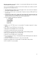
7 OPTIONAL EQUIPMENT 7.1 Performance Monitor (Option) A performance monitor is required for a radar installed on certain type of ship as determined by the Administrations. The FURUNO PM-30 (for X-band radars) covers 9410 ± 50 MHz. It works on the transponder principle. It sends response back to the radar antenna upon receiving the pulse from the radar antenna and determines if transmitter or receiver or both are deteriorated in comparison with the state of the precious calibration.
12 nm 4 arcs starting at 12 nm Transmitter: normal Receiver: normal 9 nm 9 nm Transmitter: 3 dB loss (Transmitter system has lost a half of initial power. Suspect magnetron.) Transmitter: 3 dB loss (Transmitter system has lost a half of initial power. Suspect magnetron.) Receiver: normal Receiver: 3 dB loss (Receiver has lost a half of initial sensitivity. Suspect receiver front end, water ingress in feeder system, etc.) -7.
8 1 DIGITAL INTERFACE (IEC 61162-1 Edition 1 and 2) I/O Sentences for Channel 1 Input BWC, BWR, DBK *, DBS *, DBT, DPT, GDD *, GGA, GLL, GTD *, HDG, HDM *, MDA *, MTW (*), RMA, RMB, RMC, VBW, VHB, VTG(*), ZDA (* ) not recommended in IMO type, * R-Type Only Output RSD (every 4 s), TLL * (When A/C RAIN control is pressed.) 2 * R-Type Only I/O Sentences of Channel 2 Channels 2 sentences have priority over channel 1 signals.
Position data GPS: GPGGA > GPRMC > GPGLL LC: LCRMA > LCGLL Timeout: 30 seconds Time difference (TD) LCRMA > LCGLC > LCGTD * (* R-type only0 Date, time data GPZDA Timeout: 10 seconds Course heading, speed over ground In the case of log **VBW In the case of EPFS GPS: GPVTG > GPRMC LC: LCVTG > LCRMA Speed through water **VBW Water depth data **DPT > **DBT (IMO-type) **DPT >** DBK > **DBS > **DBT (R-type) Water temperature data **MTW (IMO type) **MDA > **MTW (R-type) Waypoint range and bearing data Wi
Description of Sentences Note: Checksum for RMA, RMB and RMC is mandatory. Checksum for other sentences is evaluated if it exists. BWC - Bearing and distance to waypoint BWR - Bearing and distance to waypoint - rhumb line Time (UTC) and distance and bearing to, and location of, a specified waypoint from present position. $--BWR data is calculated along the rhumb line from present position rather than along the great circle path. $--BWC, hhmmss.ss, llll.ll, a yyyyy.yy, a, x.x, T, x.x, M, x.
DBS - Depth below sea surface $--DBS,x,x,f,x,x,M,x,x,F*hh Checksum Depth (fathoms) * Depth (meters) Depth (feet) * * Not used DBK - Depth below keel DBT - Depth below transducer Water depth referenced to the transducer. $--DBT, x.x, f, x.x, M, x.x, F*hh Checksum Water depth, fathoms * Water depth, m Water depth, feet * * Not used DPT - Depth IMO Resolution A.224 (VII). Water depth relative to the transducer and offset of the measuring transducer.
GGA - Global positioning system (GPS) fix data Time, position and fix related data for a GPS receiver. Differential reference station ID, 0000-1023 * Age of differential GPS data (see note 2) * Units of geoidal separation, m * Geoidal separation (see note 3) * Units of antenna altitude, m * Antenna altitude above/below mean sea level (geoid) * Horizontal dilution of precision * Checksum $--GGA, hhmmss.ss. 1111.11, a, yyyyy.yy, a, x, xx, x.x, x.x, M, x.x, M, x.
HDG - Heading, deviation and variation IMO Resolution A.382 (X). Heading (magnetic sensor reading), which if corrected for deviation, will produce magnetic heading, which if offset by variation will provide true heading. $--HDG, x.x, x.x, a, x.
RMA - Recommended minimum specific LORAN-C data Position, course and speed data provided by a LORAN-C receiver. Time differences A and B are those used in computing latitude/longitude. Checksum is mandatory in this sentence. This sentence is transmitted at intervals not exceeding 2 s and is always accompanied by RMB when a destination waypoint is active. RMA and RMB are the recommended minimum data to be provided by a LORAN-C receiver.
RMB - Recommended minimum navigation information Navigation data from present position to a destination waypoint provided by a LORAN-C, TRANSIT, OMEGA, GPS, DECCA, navigation computer or other integrated navigation system. Checksum is mandatory in this sentence. This sentence always accompanies RMA or RMC sentences when a destination is active when provided by a LORAN-C, TRANSIT or GPS receiver, other systems may transmit $--RMB without $--RMA or $--RMC. $--RMB, A, x.x, a, c--c, c--c, llll.ll, a yyyyy.
RMC - Recommended specific GPS/TRANSIT data Time, date, position, course and speed data provided by a GPS or TRANSIT navigation receiver. Checksum is mandatory in this sentence. This sentence is transmitted at intervals not exceeding 2 s and is always accompanied by RMB when a destination waypoint is active. RMC and RMB are the recommended minimum data to be provided by a GPS or TRANSIT receiver. All data fields must be provided, null fields used only when data is temporarily unavailable. $--RMC, hhmmss.
TLL - Target latitude and longitude Target number, name, position and time tag for use in systems tracking targets. $--TLL, xx, 1111.11, a, yyyyy.yy, a, c--c, hhmmss.
VBW - Dual ground/water speed: This sentence to be expanded as shown below: $--VBW, x.x, x.x, A, x.x, x.x, A, x.x, A, x.
ZDA - Time and date UTC, day, month, year and local time zone. $--ZDA. hhmmss.ss, xx, xx, xxxx, xx, xx*hh Checksum Local zone description, minutes * Local zone description, hours * Year Month, 01 to 12 Day, 0 to 31 UTC Not used * LOCAL = UTC + Time difference -8.
9 9.1 PARTS LOCATION and PARTS LIST ANTENNA UNIT, SCANNER OUTLINE and RF MODULE ATA Board ARP-17 (Option) 18P904A Figure A-1 Display unit, right side view Cooling Fan MMS-06C24DS-R01 RP-17 Board (Option) 03P9259C DC-PTU Board 03P9223C/D(DC spec.) AC-PTU Board 03P9228C/D(AC spec.) HV Board 03P9017A(FR-1505/1510MARK-3) 03P9017B(FR-1525MARK-3) Figure A-2 Display unit, left side view -9.
CRT RGB-BUFF Board (Option) 03P9229 SPU Board 03P9230 Figure A-3 Display unit, top view GYRO CONVERTER Board (Option) 64P1106A PM-IN Board (Option) 03P9225 Figure A-4 Display unit, rear view Figure A-5 Scanner unit -9.
IF Board 03P9232 MIC Assy. RU-9099 (For RTR-067) RU-9253 (For RTR-063) RU-9371 (For RTR-062) Diode Limiter RU-9099 RFC Board 03P9243 RT **K R-0 W 6* Figure A-6 RF module -9.
MD Board 03P9244 C Fan Motor Assy. 03-1900 J811 B J812 A Pulse Transformaer RT-9025 (For RTR-062, RTR-067) RT-9023 (For RTR-063) 4 6 Magnetron E3560, MG52389 (For RTR-067) MG5241 (For RTR-062) MG5436 (For RTR-063) Figure A-7 RF module, rear view -9.
9.2 Circuit diagrams FR-1500 Mark-3 SERIES SERIAL INTERFACE I/O CIRCUIT 03P9230 U42 SN751178NS TALKER (60 mA max) LISTENER (2 mA at 2 V) CHANNEL 1 OUTPUT RSD, TLL 4 J202 B5B-XH-A 1 TD1-A 2 TD1-B FL10 13 15 14 FL11 CHANNEL 1 INPUT BWC, BWR, DBS, etc.
FR-1500 MARK-3 series interfacing diagram CHANNEL 2 OUTPUT TTM -9.
-9.
9.3 .1 Parts list FR-1505/1515/1525 MARK-3 FR-2115/2125 ELECTRICAL PARTS LIST 98/5 SYMBOL TYPE DISPLAY UNIT RDP-119 Unit DISPLAY UNIT RDP-119 Ref. Dwg. C3464-K02-A Blk. No. CODE No.
2 Model FR-1505/1515/1525 MARK-3 FR-2115/2125 ELECTRICAL PARTS LIST 98/5 ANTENNA UNIT RSB-0074/0067/0063 Unit SCANNER UNIT Ref. Dwg. Blk. NO. C3466-K02-B SYMBOL TYPE RSB-0074/0075 CODE No.
SYMBOL TYPE CODE No. REMARKS HY801 CIRCULATOR RC-3686 000-106-850 R899 RESISTOR ERF-10HMJ102 000-123-395 TRANSFORMER RT-9025 RT-9023 000-123-823 000-123-394 6, 10, 12 KW F25 KW MAGNETRON M5436 E3566 MG5241 000-140-762 000-141-073 000-100-036 25 KW 10 KW 12 KW E3560 000-139-050 6 KW T801 V801 -9.