Back
Your Local Agent/Dealer 9-52 Ashihara-cho, Nishinomiya, Japan Telephone : 0798-65-2111 Telefax : 0798-65-4200 All rights reserved. Printed in Japan FIRST EDITION : OCT. 1993 N3 PUB.No. OME-55722 ( TENI ) FS-1562-15/25 : JUL.
SAFETY INSTRUCTIONS "DANGER", "WARNING" and "CAUTION" notices appear throughout this manual. It is the responsibility of the operator of the equipment to read, understand and follow these notices. If you have any questions regarding these safety instructions, please contact a FURUNO agent or dealer. The level of risk appearing in the notices is defined as follows: DANGER This notice indicates a potentially hazardous situation which, if not avoided, will result in death or serious injury.
DANGER WARNING Do not work inside the equipment unless totally familiar with electrical circuits. Do not operate the equipment with wet hands. Electrical shock can result. Hazardous voltage which will cause death or serious injury exists at the following locations: Keep heater away from equipment. Heat can alter equipment shape and melt the power cord, which can cause fire or electrical shock.
LIST OF CONTENTS INTRODUCTION .................................................................................................. iv Specifications of MF/HF Radiotelephone model FS-1562 ...................................... v Chapter 1 1.1 1.2 1.3 1.4 1.5 1.6 1.7 1.8 1.9 1.10 1.11 1.12 Chapter 2 OPERATION ................................................................................ 1.1 SYSTEM SET-UP ........................................................................ 1.
INTRODUCTION FURUNO Electric Company thanks you for selecting the FS-1562 MF/HF SSB Radiotelephone. We are confident you will discover why FURUNO has become synonymous with quality and reliability. To get maximum performance from your unit, please carefully read and follow the recommended procedures for operation and maintenance. The FS-1562 is an all-purpose radiotelephone system especially designed for marine mobile communication in the frequency range 1.6 to 27.5 MHz. All ITU channels are preprogrammed.
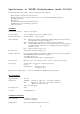
Specifications of MF/HF Radiotelephone model FS-1562 The model FS-1562-15/25 complies with the following rules and regulations: - IMO A.421(XI), A.610(15), A613(15), A.694(17) International Convention on Safety of Life at Sea 1974, as amended 1988 (GMDSS Conference) ITU Radio Regulations ETS 300 373 IEC 1097-9 draft, IEC 945 General Requirements EC EMC Directive for CE marking requirements Other relevant rules GENERAL Communication System Simplex or semi-duplex Frequency Range 1.6 to 27.
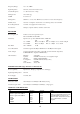
Frequency Range 1.6 to 27.5 MHz Input Impedance 50 ohms (viewed from transceiver) Antenna Required 7 to 30 meters wire or whip Tuning Power 10 to 20 W pep VSWR Less than 1.5 Tuning Time Within 2 to 15 seconds, Within 0.
Chapter 1 OPERATION 1.1 SYSTEM SET-UP The basic 24 VDC FS-1562 consists of a Transceiver Unit, a Power Amp Unit (for 250 W), an Antenna Coupler, and a Handset. Shown below are the system setup for 150 W and 250 W with DSC (Digital Selective Calling) terminal and other ancillaries.
1.
1.3 Power Supply Unit The transceiver unit FS-1562-15 or FS-1562-25 works direct on 24 VDC or through a Power Supply Unit on AC mains supply (115 or 230 VAC). The power supply unit is type PR-300 supplying 24 VDC power (20 A) to the FS-1562-15 (150 W) Transceiver Unit or type PR-850A, supplying 24 VDC (40 A) for the FS-1562-25 (250 W). Both 115/230 VAC and 24 VDC power can be connected simultaneously.
1.4 Starting operation The power switch is combined with the Volume Control. Turn the Volume Control clockwise until you hear a click. Further clockwise rotation of the control raises the loudspeaker volume. To turn off the power, turn the control fully counterclockwise until you hear the click. Adjusting the backlighting: The dimmer [9] key adjusts the backlighting for the operation display and the keyboard.
The frequencies are indicated by: Voice frequencies: Designated by the CARRIER frequency. Assigned frequencies are 1.4 kHz higher than the carrier frequencies.
Direct frequency entry Free selection is possible in Dutch Version (in marine bands only). RX: To set for a receive frequency of 1636.4 kHz, for example; Press [RX], [1], [6], [3], [6], [4], [ENT] in this order. The decimal point is not required to enter. TX: To set for a transmit frequency of 2061.4 kHz, for example; Press [TX], [2], [0], [6], [1], [4], [ENT]. DUP R 0 2 4 6 8 10 S SQ AGC NB J3E • • The [2] Cursor key shifts the cursor among last 4 places.
Custom channels Up to 200 custom channels can be programmed in addition to 412 ITU channels. You can recall them through the keyboard by channel numbers. Once a channel is selected with the keyboard, the channel can be changed with the FREQ/CH rotary selector. NOTE: Custom channel programming should be done by a FURUNO service agent.
• • The [CURS (cursor)] key shifts the cursor to band or channel number. To change the channel number, you can use the rotary control. The [FREQ/CH] control changes the number above the cursor, a band or channel designator. ITU TELEX channels To select the ITU TELEX channel 4012, for example, first select TLX with the [MODE] key. This radiotelephone is furnished with J2B class of emission. The J2B is compatible with F1B which may be used on other parties.
1.6 Transmitting After selecting class of emission and frequency, you can transmit by pressing the PTT (press-to-talk) switch Do not transmit any signal on the handset or microphone. Output power can be other than emergency during the evaluated on the operation display. silence period, 00 to 03 min and 30 to 33 min of every hour. Tuning the antenna: Maximum transmission power is achieved only when the antenna impedance and transmitter impedance match each other.
Reducing transmitter power: To conserve energy and to minimize possible interference to other stations, reduce the transmission power. This should be done when using the transceiver in a harbor, near the shore or close to communication partner (other ship). Each pressing of the [HI/LOW] key selects high or low output power. “LOW” appears on the display when low output power is selected. Low power is 60 Wpep for FS-1562-15 and FS-1562-25, both. The output power on 2182 kHz (Distress and calling) and 2187.
2. Distress calls and Distress message (1) (2) (3) Speak slowly and distinctly, “MAYDAY, MAYDAY, MAYDAY, pronounced as the French expression “m’aider”. This is; The name of your vessel and call sign three times.
1.8 In the Event of Antenna Coupler Failure HIGH TENSION HAZARD DO NOT TRANSMIT WHEN ATU IS OPENED The Antenna Coupler automatically tunes a wire or whip antenna to the transceiver. When the tuning cannot be completed for all frequencies, TUNE OK will not appear on the operation display. In this case, you can take tuning on 2182 kHz by manually operating Coupler as below: 1. Turn off the transceiver unit. Remove the cover of the Antenna Coupler. 2. Set the MANUAL-AUTO switch to the MANUAL position.
1.10 Receiving You can select a receiving frequency by one of the following methods: - Direct frequency entry, or - Channel number entry Adjusting RF gain: In normal use the RF GAIN control should be set for maximum. If the audio on the received channel is unclear or interfered with other signals, adjust (usually reduce) the RF gain to improve clarity. Clarifier adjustment: If reception is unclear, try to clarify the signal as follows.
Squelch control: Squelch is used to mute the receiver audio output when the receiver input is less than a preset value or dominant noise is higher than a preset (1000 Hz) level. To switch the squelch function ON, press the [5] SQUELCH key. Make sure the label “SQ” appears on the display. To pick up a weak signal at high audio frequencies, you should remove the squelch function notwithstanding a possible increase of background noise. To do this, press the [5] SQ switch again.
ITU channels: To select the scan group (band or channel), shift the cursor to either the position of the band or channel number by pressing the [2] CURS key. (Band scan is useful to watch frequencies on the same channel in different bands.) 2. Press the [6] SCAN key, and “SCAN” appears. The receiver starts scanning, stopping at a channel where the signal is stronger than the scan-stop level. The receiver will restart scanning when the traffic goes out of that channel.
Chapter 2 OPERATION of OPTIONAL DEVICES 2.1 Telex Communication Telex communication is performed with a Narrow-band direct-printing (NBDP) Terminal connected with an SSB transceiver. The recommended terminal for the FS-1562 is FURUNO DP-6. Other makes can also be connected with the FS-1562, if they comply with the interfacing requirements. FURUNO NBDP Terminal DP-6 No special operation is required; class of emission and frequencies are automatically set on the DP-6. Other makes of NBDP Terminal: 1.
2.2 Intercom The intercom provides communications between the FS-1562 and the RB-500 Remote Station (option). They must be wire-connected. When intercom mode is in use, there is no radio transmission. Calling RB-500 1. Press the [0] INTERCOM key. “COM” appears on the FS-1562 display panel. 2. Press [1]*, [ENT] keys. Calling beeps on the FS-1562 sound. The buzzer stops when the handset of the RB-500 is picked up. * Designated number of the RB-500 if more than one is installed. 3.
Chapter 3 CHANGING SYSTEM SETTING 3.1 SYSTEM SETUP 1. While pressing and holding down the [RCL] key, turn on the power. Release the [RCL] key when the “MEMO” appears on the display. System code Setting value MEMO 2. 3. 4. 5. Turn the FREQ/CH control to select a desired code number. Press the [RCL] key, enter desired setting by a numeral key, then press the [ENT] key. To change setting for another code, repeat steps 2 and 3. Turn off the power, then turn it on. 3.
9951 Scan/sweep-stop signal level When the receiver detects a signal whose level is stronger than the preset level it stops scanning and receives the signal. The setting on system code 9955 is available only when “0” (SQ working condition) is selected here. Setting range: 0 (Squelch working condition is effective as set on code 9995), 1-10 (S-meter level); Factory setting 3 9952 Scan/sweep-stop time When a signal is detected, the receiver stops scanning/sweeping and dwells on this channel frequency.
9958 Squelch activating frequency Setting range: 500-2000 Hz; Factory setting 1000 Hz. 9959 Sets squelch opening frequency when 2-tone alarm on 2182 kHz is received. 0: No change (frequency set on 9958) 1: 1300 Hz Factory setting 1: 1300 Hz (Loudspeaker reproduces an audio with an input at 1300 Hz as the squelch opens at that frequency.) 9999 This is for frequency programming by service technicians. Needs a password to open.
This page is intentionally left blank.
Chapter 4 MAINTENANCE 4.1 Weekly Checks Check the radiotelephone at appropriate intervals as required by Administration. For instance, Japanese Administration requires check of DSC every day. US 47 CFR 47, PART 80.869-Test of radiotelephone station calls for: Unless the normal use of the required radiotelephone station demonstrates that the equipment is operating, a test communication on a required or working frequency must be made each day the ship is navigated.
R Receiver section tested successfully. T Transmitter Exciter stage is tested successfully. T Transmitter Power Amplifier stage and Antenna Coupler (Coupler and Dummy Board) are tested successfully. If a fault is detected, “no Good” appears instead of “Good” and the associated indication blinks after completion of this test. Turn off the transceiver on completion of tests. Turn on again for normal operation. -4.
4.3 LCD/Keyboard Test & ROM Version No. Confirmation 1. While pressing and holding down the [ENT] key, turn on the power. All LCD segments appear. 2. Release the [ENT] key. 3. Press keys one by one. Check if the indication on the operation display is correct as shown below: Key 1 2 3 TX 4 5 6 RX 7 8 9 RCL 2182 0 ALARM ENT Indication Key Indication Key Indication Key Indication Example: The [2] key is pressed. The following appears.
4.4 Antenna Coupler Test The CPU and the relays which select capacitors and coils for tuning can be checked. For Competent technicians only DANGER HIGH VOLTAGE Still alive at OFF Discharge before servicing DANGER - Electrical Shock Hazard Procedure 1. Open the antenna coupler cover. 2. Open the shield cover inside the coupler. 3. Turn on No. 2 of the DIP switch S2. 4. Press the TUNE switch in the antenna coupler. 5. 24 LEDs (CR1 to CR24) light one by one every second.
4.5 Maintenance This radiotelephone equipment is designed and manufactured to provide years of intended performance. For this, a regular maintenance program should be established and should at least include the items listed in below: Item Whip antenna Check Point Remedy/Remarks Check for physical damage, corrosion and Replace damaged parts. water leakage Wire antenna Check that antenna is properly spanned and separated sufficiently apart from metallic structures. If necessary, re-span the antenna.
Item Power cable Check Point Check for loosened or corroded connection at power terminals. Remedy/Remarks Clean and tighten. Battery Check that the battery is fully charged. If discharged, charge. Feeder (coax Check for physical damage. cable, control cable) PCB connection Check that jumper cables between boards are firmly connected. Reconnect loosened connections of jumper cables. Microphone Fasten if loosened. Check that jumper cables between boards are firmly connected. -4.
Chapter 5 TROUBLESHOOTING 5.1 Troubleshooting List For qualified personnel only The troubleshooting list below gives common symptoms of equipment malfunction and means to restore normal operation. If you cannot restore normal operation, please do not check inside any unit. Any repair is best left to a qualified radiotelephone technician. Improper handling or adjustment may cause more serious damage. Troubleshooting list TROUBLE PROBABLE CAUSE Power can not be turned on The mains switchboard may be off.
TROUBLE Key input is not accepted PROBABLE CAUSE FS-1562 is under control of external equipment REMEDY "REM" appears when controlled by external equipment. Suspend operation of external operation. Antenna coupler can’t tune Antenna may be disconnected or Check antenna connection. antenna shorted to ground Antenna is out of tunable length. Recommended length is 7 to 30 meters. Poor grounding of the coupler. Check coupler ground. Breaker in coupler has tripped. Check mains voltage and polarity.
5.2 Error Indication When the FS-1562 detects a fault in the synthesizer unit (frequency unlocked), the frequency or channel number blinks. 5.3 Replacing Fuses To protect the unit from overcurrent and equipment fault, two 20 A fuses for the transceiver unit (and two 30 A fuses for the PA-2500) are provided in snap-in holders on the power cable and two fuses in the PR-300 Power Supply Unit (for 150 W set).
This page is intentionally left blank.
APPENDIX CUSTOM CHANNELS/FREQUENCIES CH NO Ship Receive (kHz) - To be programmed by Furuno Dealers Ship Transmit (kHz) -AP.
MF band working carrier frequencies - ref. US CFR 47 Part 80.371 Region East Coast West Coast Ship Transmit (kHz) 2031.5 2118.0 2126.0 2142.0 2166.0 2198.0 2366.0 2382.0 2390.0 2400.0 2406.0 2003.0 2009.0 2009.0 2031.5 2126.0 2206.0 2382.0 2430.0 Ship Receive (kHz) 2490.0 2514.0 2522.0 2538.0 2558.0 2590.0 2450.0 2482.0 2566.0 2400.0 2506.0 2450.0 2442.0 2566.0 2566.0 2522.0 2598.0 2466.0 2482.0 Region Gulf Coast Great Lakes 2 Alaska Hawaii Caribbean Guam Ship Transmit (kHz) 2009.0 2134.0 2142.
MF band SSB working carrier frequencies CH NO 241 242 243 244 245 246 247 248 249 250 251 252 253 254 255 256 257 258 259 260 261 262 263 264 265 266 267 268 269 270 Ship Receive (kHz) 1635 1638 1641 1644 1647 1650 1653 1656 1659 1662 1665 1668 1671 1674 1677 1680 1683 1686 1689 1692 1695 1698 1701 1704 1707 1710 1713 1716 1719 1722 Ship Transmit (kHz) 2060 2063 2066 2069 2072 2075 2078 2081 2084 2087 2090 2093 2096 2099 2102 2105 2108 2111 2114 2117 2120 2123 2126 2129 2132 2135 2138 2060 2063 2066 CH N
4/6 MHz ITU SSB carrier frequencies (ITU RR APPENDIX 16) The following frequencies are factory programmed.
8 MHz ITU SSB carrier frequencies (ITU RR APPENDIX 16) The following frequencies are factory programmed.
12/16 MHz ITU SSB carrier frequencies (ITU RR APPENDIX 16) 12 MHz SSB (J3E) CH NO.
18/19, 22, 25/26 MHz ITU SSB carrier frequencies (ITU RR APPENDIX 16) The following frequencies are factory programmed. 18/19 MHz SSB (J3E) CH NO.
TELEX CHANNELS MF BAND Telex FREQUENCY TABLE The following frequencies are factory programmed. 201 202 203 204 205 Ship Transmit (NBDP, DSC) 2142.0 2142.5 2143.0 2143.5 2144.0 Ship Receive (NBDP, DSC) 1607.0 1607.5 1608.0 1608.5 1609.0 206 207 208 209 210 2144.5 2145.0 2145.5 2146.0 2146.5 1609.5 1610.0 1610.5 1611.0 1611.5 211 212 213 214 215 2147.0 2147.5 2148.0 2148.5 2149.0 1612.0 1612.5 1613.0 1613.5 1614.0 216 217 218 219 220 2149.5 2150.0 2150.5 2151.0 2151.5 1614.5 1615.0 1615.5 1616.
4/6 MHz BAND ITU NBDP (Telex) FREQUENCY TABLE (ITU RR APPENDIX 32) CH NO. 4001 4002 4003 4004 4005 4006 4007 4008 4009 4010 4011 4012 4013 4014 4015 4016 4017 4018 4019 4020 4021 4022 4023 4024 4025 4026 4027 4028 4029 4030 4031 4032 4033 4 MHz TELEX SHIP RX SHIP TX 4210.5 4211.0 4211.5 4212.0 4212.5 4213.0 4213.5 4214.0 4214.5 4215.0 4177.5 4215.5 4216.0 4216.5 4217.0 4217.5 4218.0 4218.5 4219.0 4202.5 4203.0 4203.5 4204.0 4204.5 4205.0 4205.5 4206.0 4206.5 4207.0 4207.5 4219.5 4220.0 4220.5 4172.
8 MHz BAND ITU NBDP (Telex) FREQUENCY TABLE (ITU RR APPENDIX 32) 8 MHz TELEX CH NO. SHIP RX SHIP TX 8001 8376.5 8376.5 8002 8417 8377 8003 8417.5 8377.5 8004 8418 8378 8005 8418.5 8378.5 8006 8419 8379 8007 8419.5 8379.5 8008 8420 8380 8009 8420.5 8380.5 8010 8421 8381 8011 8421.5 8381.5 8012 8422 8382 8013 8422.5 8382.5 8014 8423 8383 8015 8423.5 8383.5 8016 8424 8384 8017 8424.5 8384.5 8018 8425 8385 8019 8425.5 8385.5 8020 8426 8386 8021 8426.5 8386.5 8022 8427 8387 8023 8427.5 8387.
12 MHz BAND ITU NBDP (Telex) FREQUENCY TABLE The following frequencies are factory programmed. CH NO. 12001 12002 12003 12004 12005 12006 12007 12008 12009 12010 12011 12012 12013 12014 12015 12016 12017 12018 12019 12020 12021 12022 12023 12024 12025 12026 12027 12028 12029 12030 12031 12032 12033 12034 12035 12036 12037 12038 12039 12040 12041 12042 12043 12044 12045 12046 12047 12048 12049 12050 12051 12052 12053 12054 12055 12 MHz TELEX SHIP RX SHIP TX 12579.5 12477.0 12580.0 12477.5 12580.5 12478.
12/16 MHz BAND ITU NBDP (Telex) FREQUENCY TABLE The following frequencies are factory programmed. 12 MHz TELEX CH NO. 12166 12167 12168 12169 12170 12171 12172 12173 12174 12175 12176 12177 12178 12179 12180 12181 12182 12183 12184 12185 12186 12187 12188 12189 12190 12191 12192 12193 12194 SHIP RX 12564.5 12565.0 12565.5 12566.0 12566.5 12567.0 12567.5 12568.0 12568.5 12569.0 12569.5 12570.0 12570.5 12571.0 12571.5 12572.0 12572.5 12573.0 12573.5 12574.0 12574.5 12575.0 12575.5 12576.0 12576.5 12577.
16 MHz BAND ITU NBDP (Telex) FREQUENCY TABLE The following frequencies are factory programmed. CH NO. 16111 16112 16113 16114 16115 16116 16117 16118 16119 16120 16121 16122 16123 16124 16125 16126 16127 16128 16129 16130 16131 16132 16133 16134 16135 16136 16137 16138 16139 16140 16141 16142 16143 16144 16145 16146 16147 16148 16149 16150 16151 16152 16153 16154 16155 16156 16157 16158 16159 16160 16161 16162 16163 16164 16165 16 MHz TELEX SHIP RX SHIP TX 16861.5 16743.5 16862.0 16744.0 16862.5 16744.
18/19 MHz BAND ITU NBDP (Telex) FREQUENCY TABLE The following frequencies are factory programmed. 18/19 MHz TELEX CH NO. 18001 18002 18003 18004 18005 18006 18007 18008 18009 18010 18011 18012 18013 18014 18015 18016 18017 18018 18019 18020 18021 18022 18023 18024 18025 18026 18027 18028 18029 18030 18031 18032 18033 18034 18035 18036 18037 18038 18039 18040 18041 18042 18043 18044 18045 18046 18047 18048 18049 18050 SHIP RX 19681.0 19681.5 19682.0 19682.5 19683.0 19683.5 19684.0 19684.5 19685.0 19685.
22 MHz BAND ITU NBDP (Telex) FREQUENCY TABLE The following frequencies are factory programmed. CH NO. 22001 22002 22003 22004 22005 22006 22007 22008 22009 22010 22011 22012 22013 22014 22015 22016 22017 22018 22019 22020 22021 22022 22023 22024 22025 22026 22027 22028 22029 22030 22031 22032 22033 22034 22035 22036 22037 22038 22039 22040 22041 22042 22043 22044 22045 22046 22047 22048 22049 22050 22 MHz TELEX SHIP RX SHIP TX 22376.5 22284.5 22377.0 22285.0 22377.5 22285.5 22378.0 22286.0 22378.5 22286.
22, 25/26 MHz BAND ITU NBDP (Telex) FREQUENCY TABLE The following frequencies are factory programmed. CH NO. 22151 22152 22153 22154 22155 22156 22157 22158 22159 22160 22161 22162 22163 22164 22165 22166 22167 22168 22169 22170 22171 22172 22173 22174 22175 22176 22177 22178 22179 22180 22181 22182 22183 22 MHz TELEX SHIP RX SHIP TX 22359.5 22359.5 22360.0 22360.0 22360.5 22360.5 22361.0 22361.0 22361.5 22361.5 22362.0 22362.0 22362.5 22362.5 22363.0 22363.0 22363.5 22363.5 22364.0 22364.0 22364.5 22364.