Installation Manual Color Scanning Sonar Model FSV-35/FSV-35S SAFETY INSTRUCTIONS ................................................................................................ i SYSTEM CONFIGURATION .......................................................................................... iii EQUIPMENT LISTS........................................................................................................ iv 1. HOW TO INSTALL THE SYSTEM ...............................................................
The paper used in this manual is elemental chlorine free. ・FURUNO Authorized Distributor/Dealer 9-52 Ashihara-cho, Nishinomiya, 662-8580, JAPAN All rights reserved. Printed in Japan A : JUL . 2012 B1 : MAY 07, 2013 Pub. No.
SAFETY INSTRUCTIONS The installer must read the safety instructions before attempting to install the equipment. DANGER WARNING CAUTION Indicates a potentially hazardous situation which, if not avoided, will result in death or serious injury. Indicates a potentially hazardous situation which, if not avoided, could result in death or serious injury. Indicates a potentially hazardous situation which, if not avoided, may result in minor or moderate injury.
SAFETY INSTRUCTIONS WARNING If a steel tank is installed on a wooden or FRP vessel, take appropriate measures to prevent electrolytic corrosion. CAUTION Maximum speed while the transducer is projected or being raised or lowered is as below, to prevent damage to the transducer. Projected Electrolytic corrosion can damage the hull. Be sure to power each unit with proper voltage. Raising/ Lowering 1200 mm stroke Max. 18 kn Max. 15 kn 1600 mm stroke Max. 15 kn Max.
SYSTEM CONFIGURATION Monitor Monitor USB device (mouse, etc.) Processor Unit FSV-3503 (FSV-35)/ FSV-3503S (FSV-35S) 12-24 VDC Junction Box FI-5002 NMEA IEC 61162-1 device NMEA IEC 61162-1 device Rectifier RU-1746B-2 Speaker Sub Control Unit FSV-853 100/110/115/ 220/230 VAC, 1 φ, 50/60 Hz Control Unit FSV-8501 Remote Controller FSV-854 IF Unit FSV-8502 Remote Controller FSV-854 220 VAC 3φ, 50/60 Hz Extension Kit FSV-305-5 or FSV-305-15 (Incl.
EQUIPMENT LISTS Standard supply Name Control Unit IF Unit Processor Unit Transceiver Hull Unit Installation Materials Spare Parts Type FSV-8501 FSV-8502 FSV-3503 FSV-3503S FSV-351 FSV-303 FSV-304 CP10-06000 Code No.
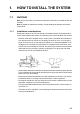
1. HOW TO INSTALL THE SYSTEM 1.1 Hull Unit Note 1: The control box on the hull unit contains a motion sensor. Handle the hull unit carefully. Note 2: Handle the transducer carefully. Rough handling will damage its sensitive components. 1.1.1 Installation considerations Decide the location of the hull unit through consultation with the dockyard and ship owner. When deciding the location, the following points should be taken into account.
1. HOW TO INSTALL THE SYSTEM 600 1000 (24”) (40”) • If the ambient temperature around the unit will be below 0°C, provide the sonar compartment with a heater to keep the temperature above 0°C. 1300 (52”) 650 (26”) Compartment Note: After you mount the hull unit, be sure to install anti-vibration stays, referring to page 1-5.
1. HOW TO INSTALL THE SYSTEM 1.1.2 Guideline for how to shorten the retraction tank Shorten the tank as necessary so that the transducer positions well below the keel when it is fully lowered. The following table provides guidelines for shortening the tank. Refer also to the retraction tank installation drawing at the back of this manual. Installation Method D D Stroke 1200 mm stroke Remove 280 -290 mm from the bottom. 1600 mm stroke Remove loss than 290 mm from the bottom.
1. HOW TO INSTALL THE SYSTEM 1.1.3 How to install the Hull Unit on the retraction tank Weld the retraction tank and allow sufficient time for cooling. Install the hull unit as follows: Prepare the materials and tools as shown below. Name Screw wrench Ethyl alcohol Waste cloths Lithium grease Molytone grease Remarks M20 (opposite side 30 mm) 99.5% For O-ring Common lithium grease (the equivalent of Daphne Eponex Grease #2) For drive shaft Molytone grease #2 (by SUMICO LUBRICANT CO., LTD) 1.
1. HOW TO INSTALL THE SYSTEM Hex. nut Spring washer Flat washer Bow mark HULL UNIT FLANGE O-ring TANK FLANGE Flat washer Hex bolt Bow Hex. nut O-ring Spring washer Flat washer Flat washer Spring washer Hex. nut O-ring Retraction Tank Stern side (7 places) Flat washer Hex. bolt Bow side (17 places) How to install the stays (anti-vibration measure) Install stays from the top of the hull unit to the ship's hull.
1. HOW TO INSTALL THE SYSTEM WRONG INSTALLATION METHOD: Stay fixed to crossbeam on overhead Stay Eye-bolt HULL UNIT CORRECT INSTALLATION METHOD: Stay installed horizontally 90° Note: Reinforce the hull unit against vibration by extending stays to prevent the damage to the transducer from the vibration.
1. HOW TO INSTALL THE SYSTEM 1.2 Processor Unit 1.2.1 Installation considerations Follow the points below to select an installation location. • Mount the unit upright. • Locate the unit out of direct sunlight and away from heat sources because of heat that can build up inside the unit. • Install the unit away from areas subject to water splash or rain.
1. HOW TO INSTALL THE SYSTEM Bulkhead installation 1. Mark locations for four self-tapping screws on the installation location. 2. Insert two self-tapping screws (6x30, supplied) at the top two screw holes, leaving approx. 5 mm of the screws exposed. 3. Hang the processor unit on the two screws inserted at step 2. 4. Insert two self-tapping screws at the bottom of the unit. 5. Tighten all screws. Self-tapping screw (6x30, 4 pcs.
1. HOW TO INSTALL THE SYSTEM 1.3 Control Unit The control unit can be installed in a console (flush mount) or on a desktop (with KB fixture). Select a location considering the following points. • Select a location where the controls can be easily operated. • Locate the unit out of direct sunlight. • Keep the unit away from water and water splash • The length of the cable connected between the control unit and interface unit is 5 or 10 m. Select a location considering the length of the cable.
1. HOW TO INSTALL THE SYSTEM 2. Make holes for four self-tapping screws (M5x20). 3. Peel the tape from the F mount gasket then attach the gasket to the rear of the control unit. 4. Connect a ground wire (1.25sq, local supply) between the ground terminal at the bottom of the unit and ship’s ground. 5. Set the unit to the cutout and fasten it with four self-tapping screws (M5x20) and wave washers. 6. Set cosmetic caps to fixing holes. 1.3.
1. HOW TO INSTALL THE SYSTEM Flush mount (option) Use the optional flush mount kit (Type: FP03-09870, Code No.: 008-535-630) to mount the sub control unit. Name Mounting plate Hex nut Wing screw Pan head screw Type 03-163-7531 M5 M5x40 M4x12 Code No. 100-306-261 000-863-108 000-162-682-10 000-163-192-10 Qty 4 4 4 4 1. Prepare a cutout in the mounting location referring to the outline drawing at the back of this manual. 2. Set the unit to the cutout. 3.
1. HOW TO INSTALL THE SYSTEM 1.5 Transducer Cable Extension Kit The transducer cable extension kit can extend the distance between the hull unit and transceiver unit. The kit is available in two versions: 5 m extension and 15 m extension. Extension Kit (Type: FSV-305-5, Code No.: 000-067-072) Name Type Code No. Junction box FSV-305 000-067-074 Cable assy. 10S2240 000-148-369-03 Cable assy. 10S2144 000-145-360 Qty Remarks 1 1 set 1 5 m, 10 pcs. 12.
1. HOW TO INSTALL THE SYSTEM 1.6 IF Unit Refer to the outline drawing at the back of this manual for mounting dimensions. Fasten the unit with 5x20 self-tapping screws. If the unit is to be installed on a bulkhead, be sure that the location does not allow water to drip into the cable entrance. 1.7 Grounding the Equipment Ground the equipment referring to the table shown below. Unit Hull Unit Processor Unit IF Unit Control Unit Transceiver Unit Junction Box (option) 1.
1. HOW TO INSTALL THE SYSTEM Hex. bolt Flat washer Hull unit flange O-ring Flat washer Spring washer Hex. nut Attachment flange O-ring Retraction tank Flat washer Spring washer Hex. nut Note: Inscribe the bow mark to the attachment flange. 1.9 Attachment Kit (option) The attachment kit permits use of the retraction tank for the CSH-20 series using the 1600 mm stroke transducer and hull unit FSV-243E/244E. Attachment kit (Type: OP10-24. Code No.
1. HOW TO INSTALL THE SYSTEM 6. Coat the threads of the bolts with a slight amount of lithium grease to prevent scorching. Insert the bolts with washers from the retraction tank flange, and then put the flat washers and spring washers in this order from above. Fasten bolts with nuts. Hex. nut Spring washer Flat washer Hull unit flange O-ring O-ring Insulation gasket Insulation gasket Insulation gasket (2) Insulation gasket (2) Flat washer Flat washer Spring washer Hex. nut Hex. bolt Hex.
1. HOW TO INSTALL THE SYSTEM This page is intentionally left blank.
2. WIRING 2.1 How to Use the Crimping Tool, Pin Extractor A special crimping tool is necessary for connection of wires to the contact pins of the 10P connector. The pin extractor removes the contact pin from the connector body. Crimping Tool 06-1001-016 2.1.1 Contact Pin 60-8017-0313-00339F (000-159-417-10) Pin Extractor 06-1877-04 (000-519-595) How to use the crimping tool 1. Remove the vinyl sheath by 3 to 4 mm to expose the core. 2.
2. WIRING 2.2 How to Connect Units PROCESSOR UNIT FSV-3503 (FSV-35)/ FSV-3503S (FSV-35S) DVI-D/D LINK (5m /10 m) MONITOR (local supply) DPYC-6 12-24 VDC 19S1050 (3 m) USB cable IF UNIT FSV-8502 SUB CONTROL UNIT FSV-853 (option) 10S2884 5m/10m FR-FTPC-CY 䋨Max. length 100 m䋩 CONTROL UNIT FSV-8501 10S2380 (Max. length 100 m) TRANSCEIVER UNIT FSV-351 10S2078 (8m) DPYCYS-2.5 100/110/115/ 220/230 VAC 1φ, 50-60Hz *1 *2 *3 10S2223 *2 *3 (effective length: 5 m, 10 pcs.
2. WIRING 2.3 Processor Unit Connect the cables of other equipment at the rear of the processor unit. Transceiver Unit (FSV-351) External Monitor (SXGA) IF Unit (FSV-8502) IF Unit (FSV-8502) FR-FTPC-CY, within 100 m 10S2383, 3 m 10S1050, 3 m DPYC-6 DVI-D/D SINGLELINK, 5 m or 10 m USB cable Ground wire IV-8sq. External speaker for PC (w/amp, less than 5W) Sub control unit FSV-853 (option) 12-24 VDC Ship’s ground Power cable Connect the power cable (DPYC-6, L=5 m, local supply) as follows: 1.
2. WIRING LAN cable Fabricate the supplied LAN cable (FR-FTPC-CY, 10/20/30/50/100 m) as shown below. Cut the vinyl sheath and armor to the lengths shown below and attach the modular connector. 150 Armor Outer vinyl sheath Inner vinyl sheath Wrap vinyl tape 1 3 2 25mm approx. 9mm Remove the outer sheath by approx 25 mm. Be careful not to damage inner shield and cores. Expose inner vinyl sheath. 4 6 5 approx. 11mm approx. 9mm Drain wire Fold back drain wire and cut it, leaving 9 mm.
2. WIRING How to extend length of cable for external monitor If the distance from the control unit to the monitor is more than 10 m, follow the procedure below to lengthen the cable, up to 70 m. The video output is analog so use an analog monitor. Part Coaxial cable Connector assy. BNC connector DVI adapter Gender converter adapter Type 1.5C2V-3C2V-T-20M 1.5C2V-3C2V-T-30M 1.5C2V-3C2V-T-70M BNCX5-DSUB15-L400 Code No., Maker 000-164-049-10 000-164-050-10 000-164-051-10 000-159-595-01 BNC-P-3 BNC-P-1.
2. WIRING 2.4 IF Unit The IF unit installs between the processor unit and the transceiver unit. Connect the cables according to the diagram inscribed on the shield cover of the IF unit. JIS cables and FURUNO cables are available for the connection. To connect the JIS cables, use the larger cable holes as shown below. Select a location that provides the maintenance space prescribed in the outline drawing.
2. WIRING How to fabricate cables Cable for ext. KP, gyro, Transceiver Unit, CIF2 Remove sheath Braided shield Vinyl tape Wrap braided shield around vinyl sheath. Cover braided shield with vinyl tape. Cable for FURUNO CIF1 equipment 45 mm Remove sheath Wrap braided shield around vinyl sheath. Cover braided shield with conductive fabric tape.
2. WIRING How to connect external KP To synchronize transmission with external sonar, make the connections shown below. • Current drive KP output IF UNIT 㪜㪯㪫㪄㪢㪧 KP signal 㪜㪯㪫㪄㪢㪧㪄㪠㪥㪄㪟 㪎 㪜㪯㪫㪄㪢㪧㪄㪠㪥㪄㪚 㪏 Sonar • Voltage drive (12 V) KP output IF UNIT 㪜㪯㪫㪄㪢㪧 KP signal 㪐 㪞㪥㪛 㪜㪯㪫㪄㪈㪉㪭㪢㪧㪄㪠㪥 㪈㪇 Sonar • Make the connections shown below to output KP for external sonar and current indicator.
2. WIRING 2.5 Control Unit and Remote Controller Ground Connect a IV-1.25 sq ground wire (local supply) between the ground terminal on the control unit and the ship’s ground. How to connect the remote controller Connect the optional remote controller (FSV-854) as shown below. 1. Unfasten the six panhead screws at the bottom of the control unit to detach the cover. Panhead screw M4x25, 6 pcs. Rear side of the control unit (cover removed) 2.
2. WIRING 3. Connect the remote controller cable to J2 on the control unit and use the support plate to fix the cable. Panhead screw M4x12, 3 pcs. Fix at copper tape. Support plate J2 Rear side of the control unit (cover removed) 4. Attach the cover. 5. At a distance of 1 cm from the control unit, attach the supplied EMI core (RFC-6) to the remote controller cable. How to connect No.2 control unit (option) Two control units can be connected. On the No.
2. WIRING 2.6 Transceiver Unit 2.6.1 How to fabricate the 10P connector (CN-B102) 400 Shield 45 40 Anticorrosive sheath Insulating tape Core Expose cores then wind shield around armor. Vinyl Sheath Armor How to fabricate 10P connector Guide Pin A Guide Pin B Position No.
2. WIRING How to position guide pins Use the guide pin insertion tool (Code No. 10-910-0179-0) to correctly insert guide pins to connectors.
2. WIRING 2.6.2 Connections inside the transceiver unit 1. Remove the transceiver unit cover. 2. Connect transducer cable (cables from the transducer) referring to cable no. labeled on the chassis and connector no. labeled on each pc board. Connect the XH connector of the cable from the transducer to the TRX board. 3. Arrange the cables in numerical order and fix them with the cable clamp. 4. Remove the metal fixing the transducer cable of the hull unit.
2. WIRING 2.7 Transducer Cable Extension Kit The transducer cable (10S2223, 10 pcs.) connects to the junction box of the kit and the junction box is connected to the transducer with a 5 m or 15 m cable (10S2240, 10 pcs.). The cable (10S2078, 8 m) that connects between the hull unit and transceiver unit is replaced with a 12.9 m cable (10S2078) or 22.9 m cable (10S2145), supplied with the kit. How to connect the junction box Connect the extension cable (10S2240, 10 pcs.
2. WIRING 2.8 Control Box of Hull Unit Connect the 3 phase power cable and the transceiver unit cable (10S2078) as shown below. CN-C101 Connect the transceiver cable (10S2078) here. TB-C101 Connect the power cable to this terminal board. LED (red) For detection of phase reversal on 3 phase power cable Confirm that the LED lights in red after the wiring is completed.
2. WIRING 2.9 Input Voltage and Fuses The transceiver unit is shipped from the factory with its input voltage set for 230 VAC and a 10 A fuse inserted in F601 and F602. For other voltages, change toggle switch positions and fuses shown below. Input voltage and toggle switch Input voltage S603 S604 S605 100 VAC 110 VAC 115 VAC 220 VAC 230 VAC L H H H H L L H L H L L L H H Default setting Default Fuses Change the fuse in F601 and F602 according to input voltage, referring to the table below.
3. ADJUSTMENTS AND CHECKS 3.1 Hull Unit Check Do not transmit when the vessel is in dry dock. How to enable transmission The default transmission state is OFF. Enable transmission as shown in the procedure below. NEVER transmit when the vessel is in dry dock, to prevent damage to the transducer. 1. Turn on the power and press the MENU/ESC key to open the menu. 2. Use the trackball to select [Others] then push the left-click button. Others Quit Edit User Program... ES Setting... 2D Map Disp Setting...
3. ADJUSTMENTS AND CHECKS 5. Select [Test] then push the left-click button. Test Board Test... Panel Test... Test Pattern... RX Test... Noise Test... TX Quit : Execute : Execute : Execute : Execute : Execute : OFF 6. Select [TX] then push the left-click button. 7. Select [On] then push the left-click button. 8. Long-press the MENU/ESC key to quit all menus. How to check the hull unit 1. Press the POWER ( | ) switch on the control unit to turn on the system.
3. ADJUSTMENTS AND CHECKS 5. Release the [DOWN] switch during lowering to confirm that the transducer stops lowering. 6. Press the [DOWN] switch again to re-start lowering. Confirm that the transducer stops at the moment when the lower limit switch is pressed. 7. Confirm that the [UP] switch operates in a similar manner. 8. Check that LEDs on the panel of the control box light as follows: 1) The UP, MD and DN LEDs light when corresponding limit switch is pressed.
3. ADJUSTMENTS AND CHECKS 4. While pressing and holding down the MENU/ESC key, press F1, F3, F5 to show the [System] menu. 5. Select [Others] then push the left-click button. 6. Select [Heading Adjust 1] then push the left-click button. 7. Rotate the scrollwheel to enter the angle measured at step 3. The setting range is -180°to 179°, in one-degree increments. 8. Select [Quit] then push the left-click button. 9. Long-press the MENU/ESC key to close all menus.
3. ADJUSTMENTS AND CHECKS TD Position 1 Ship’s Length TD Position 2 (Negative value for port) Ship's Width 6. Long-press the MENU/ESC key to close all menus. 3.4 Others Menu The [Others] menu sets the equipment according to the external equipment connected. 3.4.1 Interface Setting menu NMEA1/2 Baud Rate: Set the transmission rate for the NMEA 1 and NMEA 2 ports. (4800 bps, 9600 bps, 19200 bps, 38400 bps) CIF1/2 Baud Rate: Set the transmission rate for the CIF 1 and CIF 2 ports.
3. ADJUSTMENTS AND CHECKS 3.4.2 EXT Data Setting menu Date&Time: Select the input format for date and time data. (NONE, CIF, NMEA) Heading: Select the input format for heading data. (NONE, AD10, CIF, NMEA) Speed&Course: Select the input format for ship’s speed and course data. (NONE, CIF, NMEA) Speed Sensor: Select the input format for speed data. (NONE, GPS/DR, DOPPLER/ DR) If response is slow, select GPS. Lat/Lon: Select the input format for position data.
APPENDIX 1 JIS CABLE GUIDE Cables listed in the manual are usually shown as Japanese Industrial Standard (JIS). Use the following guide to locate an equivalent cable locally. JIS cable names may have up to 6 alphabetical characters, followed by a dash and a numerical value (example: DPYC-2.5). For core types D and T, the numerical designation indicates the cross-sectional Area (mm2) of the core wire(s) in the cable.
0 # / ' 1 7 6 . + 0 ' +056#..#6+10 /#6'4+#.5 70+6 %2 %2 %2 (58 , ' 0 # / ' 1 7 6 .
࡙࠾࠶࠻ &1%7/'06 +056#..#6+10 /#6'4+#.5 52#4' 2#465 70+6 % %2 (47&& #((/ . %2 52 (58 5 &'5%4+26+10 %1&' ͳ 0 # / ' 1 7 6 .
࡙࠾࠶࠻ 0 # / ' 1 7 6 . + 0 ' (8 .( / 575 / 575 / 575 / : 575 9'# 41*5 %1 # 8 % 52 (58 &'5%4+26+10 %1&' ͳ 3 6; % < $ % < & 䋨⇛࿑䈱ኸᴺ䈲䇮ෳ⠨୯䈪䈜䇯㩷㩷㪛㪠㪤㪜㪥㪪㪠㪦㪥㪪㩷㪠㪥㩷㪛㪩㪘㪮㪠㪥㪞㩷㪝㪦㪩㩷㪩㪜㪝㪜㪩㪜㪥㪚㪜㩷㪦㪥㪣㪰㪅䋩 .1%#. #55'/$.
࡙࠾࠶࠻ 1 7 6 . + 0 ' %2 /, # 52( % %# / %2 (58 &'5%4+26+10 %1&' ͳ 3 6; % < & % < % 䋨⇛࿑䈱ኸᴺ䈲䇮ෳ⠨୯䈪䈜䇯㩷㩷㪛㪠㪤㪜㪥㪪㪠㪦㪥㪪㩷㪠㪥㩷㪛㪩㪘㪮㪠㪥㪞㩷㪝㪦㪩㩷㪩㪜㪝㪜㪩㪜㪥㪚㪜㩷㪦㪥㪣㪰㪅䋩 +056#..#6+10 /#6'4+#.5 70+6 䋨⇛࿑䈱ኸᴺ䈲䇮ෳ⠨୯䈪䈜䇯㩷㩷㪛㪠㪤㪜㪥㪪㪠㪦㪥㪪㩷㪠㪥㩷㪛㪩㪘㪮㪠㪥㪞㩷㪝㪦㪩㩷㪩㪜㪝㪜㪩㪜㪥㪚㪜㩷㪦㪥㪣㪰㪅䋩 +056#..#6+10 /#6'4+#.5 Ꮏ᧚ᢱ 219'4 %#$.' #55'/$.; 㩃㨺㩖㩨㩣⚵ຠ/, %#$.' #55'/$.; .#0 㩃㨺㩖㩨㩣 㩂㩚㩕㩧 .
ᢙ㊂ 3 6; ↪ㅜ㧛⠨ 4'/#4-5 ㅍฃାⵝ⟎↪ (14 64#05%'+8'4 70+6 ㅍฃାⵝ⟎↪ (14 64#05%'+8'4 70+6 ㅍฃାⵝ⟎↪ (14 64#05%'+8'4 70+6 ㅍฃାⵝ⟎↪ (14 64#05%'+8'4 70+6 ⇟ ภ 01 %10&7%6+8' %.16* 6#2' ዉ㔚ᕈᏓ㩍㨺㩖㩩 %#$.'ޓ6+' 㩄㩧㩗㩨㨹㩂㩇 5'.( 6#22+0) 5%4'9 㩎㩡㩇㩊㨹㩕㩩㩧㩒㩆㩨 ޓ㩆㨷 ฬޓޓ⒓ 0#/' ⇛ޓޓ࿑ 176.
%#$.'ޓ6+' 㩄㩧㩗㩨㨹㩂㩇 5'.( 6#22+0) 5%4'9 㩎㩡㩇㩊㨹㩕㩩㩧㩒㩆㩨 ޓ㩆㨷 ฬޓޓ⒓ 0#/' ⇛ޓޓ࿑ 176.+0' %1&' 01 %8 0 %1&' 01 : 575 ဳฬ㧛ⷙᩰ &'5%4+26+105 /27 (58 (58 5 %2 6;2' ᢙ㊂ 3 6; ↪ㅜ㧛⠨ 4'/#4-5 #; : 㧲㨁㧾㨁㧺㧻ޓ㧱㧸㧱㧯㨀㧾㧵㧯ޓ㧯㧻ޓ㧚㧘㧸㨀㧰 㧔⇛࿑ߩኸᴺߪޔෳ⠨୯ߢߔ&ޓޕ+/'05+105 +0 &4#9+0) (14 4'('4'0%' 10.; 㧕 % / % 691 6;2'5 #0& %1&'5 /#; $' .+56'& (14 #0 +6'/ 6*' .19'4 241&7%6 /#; $' 5*+22'& +0 2.
).#55 67$' (75' 㩕㨷㨺㩇㩨 ).#55 67$' (75' 㩕㨷㨺㩇㩨 ()$1 8 # ()$1 8 # 2$( 2'4 8'5 (75' 㩕㨷㨺㩇㩨 ()/$ # 8 ()/$ 8 # 2$( &9) 01 14 6;2' 01 2'4 8'5 ਅⵝ⟎ ᓮེ↪ (14 *#.. 70+6 5'65 2'4 8'55'. 4'/#4-5 %1&' 01 % 2 $ 52#4' %1 : $1: 01 2 ဳᑼ 㩄㨺㩎㩨⇟ภ߇㧞Ბߩ႐วޔਅᲑࠃࠅᲑߦઍࠊࠆㆊᷰᦼຠߢࠅޔ߅ߥޓޕߔ߹ߡߞ߇߆ࠄߜߤޔຠ⾰ߪᄌ ࠊࠅ߹ߖࠎޕ 691 6;2'5 #0& %1&'5 /#; $' .+56'& (14 #0 +6'/ 6*' .
13/Sep/2011 Y.
13/Sep/2011 Y.
5/Nov/2010 Y.
D-4 Y.
D-5 23/Apr/2013 Y.
D-6 23/Apr/2013 Y.
D-7 13/Sep/2011 Y.
D-8 13/Sep/2011 Y.
13/Sep/2011 Y.
13/Sep/2011 Y.
13/Sep/2011 Y.
D-12 13/Sep/2011 Y.
D-13 Takahashi T. Y.
1 2 *1 DPYCYS-2.5 (10/20m *2) VV-SBCJ-0.3x14P,8m,φ17 ミドリ GRN P (10S2078) アカ RED アオ BLU P クロ BLK ムラサキ PPL P シロ WHT チャ BRN P TT クロ BLK チャ BRN P *1 シロ WHT TB-C101 TPYCY-4 U 1 アオ BLU P V 2 シロ WHT W 3 キ YEL P 4 クロ BLK 5 シロ WHT P 6 クロ BLK 7 ムラサキ PPL P 8 クロ BLK アカ RED P シロ WHT *1 制御器 PE IV-8sq. ミドリ GRN RAISE/LOWER UNIT 保護アース P クロ BLK FSV-2431 アカ RED P クロ BLK 上下装置 ミドリ GRN P HULL UNIT シロ WHT FSV-303/304 キ YEL P シロ WHT *3 距離:5m以下 DISTANCE: MAX.