COLOR DGPS/PLOTTER/SOUNDER COLOR GPS/PLOTTER/SOUNDER GP-1650WDF, GP-1650WF FURUNO/NAVIONICS GP-1650WDF, GP-1650WF FURUNO/C-MAP NT
Your Local Agent/Dealer 9-52 Ashihara-cho, Nishinomiya, Japan Telephone : 0798-65-2111 Telefax : 0798-65-4200 All rights reserved. Printed in Japan FIRST EDITION : AUG. 2002 B PUB.No. OME-44242 ( HIMA ) GP-1650WF/1650WDF : AUG.
SAFETY INSTRUCTIONS WARNING CAUTION Do not use the equipment for other than its intended purpose. Do not open the equipment. Hazardous voltage which can cause electrical shock, burn or serious injury exists inside the equipment. Only qualified personnel should work inside the equipment. No one navigation device should ever be solely replied upon for the navigation of a vessel. Do not disassemble or modify the equipment.
TABLE OF CONTENTS FOREWORD .................................. iv SYSTEM CONFIGURATION ......... v WHAT IS WAAS?........................... vi 1. OPERATIONAL OVERVIEW 1.1 1.2 1.3 1.4 1.5 1.6 1.7 1.8 Display Unit Controls .....................1-1 Inserting Mini Chart Card ...............1-2 Turning the Power On/Off ..............1-2 Adjusting Tone and Brilliance .........1-3 Plotter Displays..............................1-4 Sounder Displays...........................1-4 Menu Operation, Soft Keys ..........
TABLE OF CONTENTS 7. ROUTES 12. USING C-MAP NT MODEL 7.1 7.2 7.3 7.4 7.5 Entering Routes............................. 7-1 Connecting Routes ........................ 7-2 Inserting, Removing Waypoints ..... 7-3 Creating Track-based Routes ........ 7-5 Erasing Routes.............................. 7-6 12.1 12.2 12.3 12.4 8. NAVIGATION 8.1 8.2 8.4 8.5 Navigating to “Quick Points” .......... 8-1 Navigating to Waypoints (waypoint list) ................................
FOREWORD A Word to GP-1650WDF/1650WF Owners Navigation information is displayed on a bright 5.6-inch color TFT LCD. On-screen information shown are position, range and bearing to cursor position, range, bearing, ETA and TTG to waypoint, etc. A high sensitivity receiver tracks up to twelve (WAAS: thirteen) satellites simultaneously. An 8-state Kalman filter ensures optimum accuracy in determination of vessel position, course and speed.
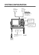
SYSTEM CONFIGURATION GPA-017 (GP-1650WF) GPA-019 (GP-1650WDF) ANTENNA UNIT Receives signal from GPS satellite and beacon reference station. (GP-1650WDF only) DISPLAY UNIT External equipment (Autopilot, etc.
WHAT IS WAAS? WAAS, available in North America, is a provider in the worldwide SBAS (Satellite Based Augmentation System) navigation system. An SBAS provider furnishes GPS signal corrections to SBAS users. Two more SBAS providers are also currently under development, MSAS (Multi-Functional Satellite Augmentation System) for Japan and EGNOS (Euro Geostationary Navigation Overlay Service) for Europe. All providers will be compatible with one another, thus providing “seamless” position fixes to SBAS users.
1. OPERATIONAL OVERVIEW This chapter acquaints you with the basics of your unit - from turning on the power to the soft key menu operation. 1.1 Display Unit Controls • Registers own ship's positions. • Marks man overboard position, event position. Cursor pad • Shifts cursor and display. • Selects items on menus. Registers items on menus. SAVE MOB ENTER Soft key's functions change depending on the display.
1. OPERATIONAL OVERVIEW 1.2 Inserting Mini Chart Card Insert appropriate mini chart card before turning on the power. Note: Static electricity can be passed through your fingers to a memory card and destroy the contents of the card. To prevent this, always touch a metallic object, such as a steel desk, before handling a memory card. 1.3 Turning the Power On/Off Turning the power on Press the [POWER/BRILL] key at bottom left-hand side of the display unit to turn on the power.
1. OPERATIONAL OVERVIEW When the satellite signal is being received normally, the GP-1650WDF/1650WF displays various abbreviations at the bottom left-hand corner of the display which show DGPS/GPS receiver status. The table in below shows these abbreviations and their meanings. 1.4 1. Press the [POWER/BRILL] key with a touch-and-release action. The tone and brilliance setting window appears.
1. OPERATIONAL OVERVIEW 1.5 Plotter Displays 1.6 Press the [PLOT] key. Each time this key is pressed, the display mode changes in the sequence shown below. For display mode, refer to Chapter 3. Sounder Displays Three sounder displays are available: Normal, Dual-frequency display and Plotter/Sounder display. You may select a sounder display with the [SNDR] key.
1. OPERATIONAL OVERVIEW 1.7 Menu Operation, Soft Keys 3. Select item with the cursor pad, and press the EDIT soft key. For example, select TIME DISPLAY. Most operations are carried out through the menu which is opened and closed with the [MENU] key. Menus may be selected with the five soft keys to the right of menus. Options are selected with the cursor pad. 12 HOUR 24 HOUR Time display window 1. Press the [MENU] key to display the main menu.
1. OPERATIONAL OVERVIEW 1.8 Demonstration Display The demonstration display provides simulated operation of this unit. On the plotter display, own ship tracks, at the speed selected, a figure eight course or any course you enter, starting from position entered. All controls are operative; you may set destination, enter waypoints, etc. Simulated sounder operation is also provided. 1. Press the [MENU] key, followed by the CONFIGURATION and SYSTEM MENU soft keys to open the system menu. 2.
2. VIDEO SOUNDER OPERATION 2.1 Principle of Operation The video sounder determines the distance between its transducer and underwater objects such as fish, lake bottom or seabed and displays the results on screen. It does this by utilizing the fact that an ultrasonic wave transmitted through water travels at a nearly constant speed of 4800 feet (1500 meters) per second.
2. VIDEO SOUNDER OPERATION 2.2 2. Press the MODE/FREQ soft key. The display changes as below. Sounder Display Description The figure below shows all indications and markers which may appear on the normal sounder display. MODE/FREQ Nav information window 34° 12.345' N 135° 12.345' E Minite mark Color bar Functions for soft keys F Depth scale CSE 245.8° SPD 16.3kt RANGE 20 60 30 GAIN Temp. scale Water temp. Graph SHIFT 40 0 Water temp.
2. VIDEO SOUNDER OPERATION Selecting sounder display mode Bottom-zoom display There are five display modes from which to choose: normal, marker zoom, bottom zoom, bottom lock and A-scope. To select a display, press the SNDR FUNC soft key on the normal sounder display to show the sounder function window, and press ▲ or ▼ to select the display. Press the RETURN soft key to close the window.
2. VIDEO SOUNDER OPERATION A-scope display 2.4 This display shows echoes at each transmission with amplitudes and tone proportional to their intensities, on the right of the screen. It is useful for estimating the kind of fish school and seabed composition. This display provides the plotter display on the left part of the screen and the normal sounder display on the right part. It is useful for searching fish schools at cruising speed.
2. VIDEO SOUNDER OPERATION 2.5 Automatic Sounder Operation Dual-frequency display: Press the MODE soft key. MODE/FREQ ▲ AUTO CRUISING AUTO FISHING MANUAL ▼ Automatic sounder operation is useful when you are preoccupied with other tasks and do not have time to adjust the display. How the automatic sounder works The automatic sounder function automatically selects the proper gain, range scale and clutter suppression level according to depth.
2. VIDEO SOUNDER OPERATION Selecting display range Press the RANGE soft key to show the range window, and select range by the cursor. Press the RETURN soft key to finish. RANGE ▲ 15 ft 30 ft 60 ft 120 ft 200 ft 400 ft 1000 ft 2500 ft ▼ Range window Adjusting the gain Press the GAIN soft key to show the gain window, and press ▲ or ▼ to set the gain. Current level is shown above the bar. Press the RETURN soft key to finish.
2. VIDEO SOUNDER OPERATION 2.7 Measuring Depth The VRM functions to measure the depth to fish schools, etc., and it is always displayed. 1. Press ▲ or ▼ to shift the VRM. 2. Read the depth just above the VRM. VRM 3. Press ▲ or ▼ to select degree of suppression desired; OFF, NL1, NL2 or NL3. The higher the number the greater the degree of suppression. 4. Press the RETURN soft key and the [SNDR] key to finish. Depth to VRM SOUNDER RANGE 17.
2. VIDEO SOUNDER OPERATION 3. Press ▲ or ▼ to select clutter rejection level desired; 0 (OFF) through 9. The higher the number the greater the degree of suppression. Note that weak echoes may not be displayed when the clutter circuit is on. 4. Press the RETURN soft key and the [SNDR] key to finish. 4. Press the RETURN soft key and the [SNDR] key to finish. Weak echoes Appearance of weak echoes 2.11 White Marker Appearance of clutter 2.
2. VIDEO SOUNDER OPERATION White marker shows ← color currently displayed in white. Color bar when white marker function is active 4. Press the RETURN soft key and the [SNDR] key to finish. To turn the white marker function off, display “0” in the white marker window. 2.12 Selecting Picture Advance Speed The picture advance speed determines how quickly the vertical scan lines run across the screen.
2. VIDEO SOUNDER OPERATION 4. Press the RETURN soft key and the [SNDR] key to finish. ALARM2 BOTTOM ALARM FISH (B/L) ALARM FISH (NORMAL) TEMP. ALARM OFF OFF OFF OFF EDIT 2.14 Alarms Bottom alarm The bottom alarm sounds when the bottom echo is within the alarm range set. To activate the bottom alarm the depth must be displayed.
2. VIDEO SOUNDER OPERATION 2.15 Interpreting the Display Bottom echo Zero line Echoes from the bottom are normally the strongest and are displayed in reddish-brown color but the color and width will vary with bottom composition, water depth, frequency, sensitivity, etc. The zero line (sometimes referred to as the transmission line) represents the transducer’s position, and moves off the screen when a deep phased range is used.
2. VIDEO SOUNDER OPERATION Surface noise/Aeration When the waters are rough or the boat passes over a wake, surface noise may appear near the zero line. As surface turbulence is acoustically equivalent to running into a brick wall, the bottom echo will be displayed intermittently. Similar noise sometimes appears when a water temperature difference (thermocline) exists. Different species of fish tend to prefer different temperature zones, so the thermocline may be useful to help identify target fish.
3. PLOTTER DISPLAYS 3.1 Presentation Modes The plotter display mainly shows chart, ship’s track, waypoints, and navigation data. Three types of display presentations are provided for the normal plotter display: north-up, course-up and auto course-up. To change the mode, use the presentation mode selection soft key, which is the 3rd soft key from the top. screen and points to north. A filled triangle marks own ship’s position.
3. PLOTTER DISPLAYS 3.2 Cursor 3.3 Shifting the Display Turning on the cursor, shifting the cursor The display can be shifted on the plotter display. Press the cursor pad to turn the cursor on, and the cursor appears at the own ship’s position. Operate the cursor pad to shift the cursor. The cursor moves in the direction of the arrow or diagonal pressed on the cursor pad. 1. Press the cursor pad to display the cursor. 2. Locate the cursor at a screen edge.
3. PLOTTER DISPLAYS 3.5 Selecting Chart Scale/Range Chart scale (range) may be selected with the ZOOM IN or ZOOM OUT soft key. ZOOM IN expands the chart; ZOOM OUT shrinks it. 3.6 Mini Chart Cards The mini chart cards contain nautical charts. When you insert a suitable mini chart card in the slot and your boat is near land, a chart appears. When a wrong card is inserted or a wrong chart scale is selected, the land will be hollow. Insert the proper card and select a suitable chart scale.
3. PLOTTER DISPLAYS FURUNO chart symbols Symbol Description Summit Wreck Lighthouse Lighted Buoy Buoy Sample chart (Japan and South Korea) Radio Station showing indices Position of Sounding Remarks on chart display Obstruction A chart will not be displayed in the following conditions: Fishing Reef • When the chart scale is too large or too Platform small. When this happens, select proper chart scale. • When scrolling the chart outside the indices.
3. PLOTTER DISPLAYS Aid to navigation data Selected FURUNO and NAVIONICS mini chart cards can show buoy and lighthouse data. Simply place the cursor on the lighthouse or buoy mark. Place the cursor on a lighthouse or buoy mark. Placing the cursor on the mark Example of data displayed Range and bearing from own ship Period (ex.: 6 seconds) Visibility in nautical mile (ex.: 12 miles) Port service icons (Nav-ChartsTM cards) Selected Nav-ChartsTM mini chart cards show by icons services available at ports.
3. PLOTTER DISPLAYS 3.7 Navigation Data Display The navigation data display provide generic navigation data and DGPS/GPS information. Press the [PLOT] several times to show the navigation data display. Position Date DATE: JUN 30 2002 POSITION Range to waypoint TIME 23:59:59 TRIP:123nm Press the SAT INFO soft key. Your display should look something like the following illustration. LAT LON 12.5 TD 123.25 nm kt DATE: JUN 30 2002 ZOOM 359.9° 299.9° SAT INFO 65.8°F DEP 20.
3. PLOTTER DISPLAYS Beacon information display 3.8 The DGPS beacon receiver-equipped model, can show DGPS reference station information. Press the BEACON INFO soft key to show the DGPS reference station information. The steering display provides steering information such as range, bearing, ETA to destination, course and speed. Press the [PLOT] key several times to show the steering display.
3. PLOTTER DISPLAYS How to read the XTE indication 3.9 The black boat-shaped mark shows own boat’s movement and direction, and the amount to steer to return to course. Using the figure shown on the previous page as an example, you would steer right by 000.02 nautical miles to return to course. When this mark is out of range of the XTE scale, the mark color changes from black to yellow. The range of the XTE scale can be set as shown below.
3. PLOTTER DISPLAYS 3.10 Changing Operation Mode Operation mode can be changed among PLEASURE, FISHING1 and FISHING2. FISHING1 or 2 mode provides mark/line entry at the cursor or own ship’s position. On FISHING 1 or 2 modes, pressing the [HIDE/SHOW] key changes the function of soft keys. Holding track, changing track color, and selecting color and form of mark/line can be performed by the soft keys directly. For detailed information of FISHING 1 and FISHING 2 modes, see Chapter 5. 34° 12.345' N 135° 12.
3. PLOTTER DISPLAYS Selecting fishing 1, fishing 2 mode 3.11 Navigation Trip Distance 1. Press the [MENU] key and the DISPLAY OPTIONS soft key. The display setup1 menu appears. The navigation trip distance is displayed on the navigation data display. Press the [PLOT] key several times to show the navigation data display.
4. TRACK 4.1 Displaying Track 1. Press the [MENU] key to open the main menu. MENU CHART SETUP OPTIONS DISPLAY OPTIONS GPS/DGPS/TD OPTIONS SOUNDER SETUP OPTIONS DGPS 3D CONFIGURATION Main menu 2. Press the CHART SETUP OPTIONS soft key to open the CHART SETUP OPTIONS menu. CHART SETUP CHART OFFSET The default setting is ON, which traces ship’s track in accordance with ship’s movements. Number of track and mark points used appears in the TRACK STATUS window on the TRACK CONTROL menu.
4. TRACK When the fishing 1 or 2 mode is selected, you can stop or restart plotting the track with the soft key only on the plotter display. Press the [HIDE/SHOW] key several times to show the STOP TRACK soft key on the plotter display. Press the STOP TRACK soft key to stop plotting of track. The message of HOLD TRACK PLOTTING appears approx. 2 seconds and then own ship mark changes to hollow circle. To restart plotting the track, press the START TRACK soft key again.
4. TRACK Track plotting interval 1. Press the [MENU] key followed by the CHART SETUP OPTIONS and TRACK CONTROL soft keys. 2. Press ▲ or ▼ to select TIME INTERVAL or DIST INTERVAL. 3. Press the EDIT soft key to display the INTERVAL window. 3. Press the EDIT soft key to display the TRACK MEMORY window. TRACK MEMORY 1000/5000 POINTS Track memory window TIME INTERVAL 01 m 00 s (When selecting TIME INTERVAL.) DIST INTERVAL The track memory window may be erased by pressing the CANCEL soft key to escape. 4.
4. TRACK 4.6 Erasing tracks by color Erasing Tracks Be absolutely sure you want to erase track; erased track cannot be restored. Erasing tracks by area You can erase tracks within an area you set. 1. Press the [MENU] key followed by the CHART SETUP OPTIONS, TRACK CONTROL and ERASE T & M soft keys. ERASE ALL TRACKS ERASE TRACKS BY AREA ERASE TRACKS BY COLOR ERASE ALL MARKS/LINES ERASE MARKS BY AREA ERASE EDIT Tracks can be erased by on color. 1.
5. MARK You can enter marks to denote important locations, such as a good fishing spot. In the default condition, you may enter 3000 marks. Plotter display 34° 12.345' N 135° 12.345' E CSE 245.8° SPD 16.3kt ZOOM QP<01> 5.1 IN ZOOM OUT Entering Marks Select the FISHING 1 or FISHING 2 mode to enable entry of marks on the PLOTTER display. Select the location desired with the cursor, or turn off the cursor to enter the mark at own ship position. Press the MARK ENTRY soft key to enter the mark.
5. MARK Video sounder display 34° 12.345' N 135° 12.345' E CSE 245.8° SPD 16.3kt 5.2 You can select shape, line and color of marks and lines on the plotter display. SOUNDER RANGE 15.0 30 20 20 30 1. Press the [HIDE/SHOW] key to show the MARK EDIT soft key. 2. Press the MARK EDIT soft key to show the MARK/LINE window. GAIN SHIFT 10 0 40 DGPS 3D MODE/ FREQ 50 32.0 Changing Mark Attributes SNDR FUNC 50k MARK EDIT Press the [HIDE/SHOW] key. 34° 12.345' N 135° 12.345' E CSE 245.
5. MARK Mark line 5.3 Press the MARK LINE soft key to display the MARK LINE window. Press ▲ or ▼ to select mark line desired. Mark size can be selected from STD (standard) and SMALL. MARK LINE ▲ Mark does not have a line. ▼ Changing Mark Size 1. Press the [MENU] key to display the main menu. 2. Press the CHART SETUP OPTIONS soft key. 3. Press the CHART DETAILS soft key to open the CHART DETAILS menu. Mark line window Mark color Press the MARK COLOR soft key to display the MARK COLOR window.
5. MARK 5.4 Erasing Marks Erasing individual marks/lines 1. Operate the cursor pad to place the cursor on the mark you want to erase. 2. Press the [CLEAR] key. The mark selected is erased. Note: To erase a line, place the cursor on an edge of the line. The line segment will be erased. Erasing marks/lines in an area You can erase marks and lines within an area you select. 1. Press the [MENU] key followed by the CHART SETUP OPTIONS, TRACK CONTROL and ERASE T & M soft keys. 2.
6. WAYPOINTS 6.1 Entering Waypoints In navigation terminology, a waypoint is a particular location on a voyage whether it be a starting, intermediate or destination point. A waypoint is the simplest piece of information your equipment requires to get you to a destination, in the shortest distance possible. This unit has 835 waypoints (including quick waypoints) into which you can enter position information.
6. WAYPOINTS 2. Press the WAYPOINTS soft key to display the WAYPOINTS menu. ADD/EDIT/MOVE WAYPOINTS WPT LOCAL LIST Changing the shape and color of waypoint mark 1. Press the SELECT MARK soft key. 2. Press the MARK SHAPE soft key to open the mark shape selection window. ALPHA/NUMERIC LIST MARK SHAPE WAYPOINT BY CURSOR WAYPOINT BY RANGE & BEARING RETURN DGPS 3D Waypoints menu 3. Press the WAYPOINT BY CURSOR soft key. The plotter display appears. 4.
6. WAYPOINTS Changing waypoint name, comment, proximity alarm radius Entering waypoints by range and bearing 1. If necessary, you can change the name (up to 6 characters), comment (up to 13 characters), L/L position and the proximity alarm radius (explained in detail in Chapter 8) as follows: a) Select the NAME, COMMENT or This method is useful when you want to enter a waypoint using range and bearing to a target found on a radar. PROXIMITY ALARM RADIUS field.
6. WAYPOINTS Entering waypoints by latitude and longitude position 1. Press the [WPT/RTE] key to open the WAYPOINT & ROUTE menu. 2. Press the WAYPOINTS soft key to open the WAYPOINT menu. 3. Press the LOCAL LIST (lists waypoints in order from nearest to furthest) or ALPHA/NUMERIC LIST (lists waypoints in alphanumeric order) soft key. BRG. WPT LOCAL 23.8° 1.75nm FISH01 RNG. 33°12.345' N ABCDEFGHIJKL 135°23.456' W GO TO WPT001 12:30 29SE97 BRG. 90.0° RNG. 2.51nm 33°23.456' N 135°23.567' W BRG.
6. WAYPOINTS 6.3 Changing Waypoint Data You can change the waypoint data through the waypoint list. 1. Press the [WPT/RTE] key, WAYPOINTS, and LOCAL LIST or ALPHA/NUMERIC LIST soft keys. 2. Press ▲ or ▼ to select the waypoint you want to change. 3. Press the EDIT WPT soft key. 4. Change data as you did in “Entering waypoints by the cursor.” 5. Press the SAVE soft key. 6.4 Changing Waypoint Position on the Plotter Display You may change the position of waypoints on the plotter display as follows: 1.
6. WAYPOINTS 6.5 Waypoint Mark Size You may change the size of all waypoint marks to small or large (default), or turn them off. 1. Press the [MENU] key to open the main menu. 2. Press the CHART SETUP OPTIONS soft key. 3. Press the CHART DETAILS soft key to open the CHART DETAILS menu. 6.6 Searching Waypoints You can search for a waypoint through the alphanumeric list as follows: 1. Press the [WPT/RTE] key, and then press the WAYPOINTS and ALPHA/NUMERIC LIST soft keys to show the alpha/numeric list.
7. ROUTES Often a trip from one place to another involves several course changes, requiring a series of route points (waypoints) which you navigate to, one after another. The sequence of waypoints leading to the ultimate destination is called a route. Your unit can automatically advance to the next waypoint on a route, so you do not have to change the destination waypoint repeatedly. You can store up to 200 routes. A route may consist of 35 points. 7.
7. ROUTES 4. If desired you can change the route name shown and/or add a comment. To change route name, press the [CLEAR] key to clear the route name. Use the cursor pad to position the cursor and then press appropriate alphanumeric key. To enter a comment, place the cursor in the COMMENT window. Use the cursor pad and alphanumeric keys to enter your comment. A route name may consist of six characters; comment, 13 characters. 5. Press the LOCAL LIST or ALPH LIST soft key to open the waypoint list. 6.
7. ROUTES 7.3 Inserting, Removing Waypoints Inserting waypoints through the route list Waypoints can be inserted in routes as follows: 7. Press ▲ or ▼ to select the waypoint you want to insert. You can switch between the local list and alphanumeric list by pressing the LOCAL LIST or ALPH LIST soft key. 8. Press the SELECT WPT soft key. Changing waypoints through the list 1. Press the [WPT/RTE] key followed by the ROUTES soft key to open the ROUTE menu. 2. Select a route by pressing ▲ or ▼. 3.
7. ROUTES Inserting waypoints on the plotter display Inserting waypoints before the first waypoint or after the last waypoint 1. Press the [WPT/RTE] key followed by the ROUTES soft key to open the ROUTE menu. 2. Press ▲ or ▼ to select the route desired. 3. Press the EDIT ROUTE soft key. 4. Press the PLOT soft key to show the plotter screen. 5. Operate the cursor pad to place the cursor on the first or last waypoint of the route which you want to insert. 6. Press the ADD TO START (ADD TO END) soft key. 7.
7. ROUTES 7.4 Creating Track-based Routes You can create routes based on your ship’s track by entering waypoints at own ship’s position. This feature is useful when you wish to retrace a track. 1. Press the [WPT/RTE] key to open the WAYPOINT & ROUTE menu. 2. Press the CREATE VOYAGE BASED ROUTE soft key to show the save route menu. 4. If required, you may change the route name and enter a comment, using the [CLEAR] key, cursor pad and alphanumeric keys. 5.
7. ROUTES 7. Press the [SAVE/MOB] key with a touch-and-release action to enter a waypoint mark at own ship position. A new waypoint is created under the next consecutive waypoint number and that waypoint is added to the route. 8. Repeat step 7 whenever you change course. 35 waypoints can be entered. 9. To stop creating the track-based route, press the [WPT/RTE] key followed by the CREATE VOYAGE BASED ROUTE soft key. 10. Press the FINISH LOG soft key to register the route. The SAVE icon disappears. 7.
8. NAVIGATION 8.1 Navigating to “Quick Points” The “quick point” feature allows you to navigate to point(s) without retaining the data indefinitely in your unit’s memory. Each time a quick point is entered previous quick points have the same numbers as newly entered ones are written over. A light-blue line connects between own ship and destination, marked “QP<01>”, and it shows the shortest course to the destination. Arrows on the line show the direction to follow to get to the quick point.
8. NAVIGATION 8.2 Navigating to Waypoints (waypoint list) 1. Press the [WPT/RTE] key to open the WAYPOINT & ROUTE menu. 2. Press the WAYPOINTS soft key to open the WAYPOINTS menu. 3. Press the LOCAL LIST or ALPHA/NUMERIC LIST soft key to show corresponding waypoint list. 4. Select a waypoint. 5. Press the GO TO soft key. The plotter display appears. A light-blue line runs between destination selected and own ship’s position. Arrows on the line show the direction to follow.
8. NAVIGATION + SELECT PORT SERVICE 40°45.971'N 13°57.462'E FROM OS 0.26 nm 180.2° GO TO PUNTA CORNACCHIA ACCO AMENO ENTER ISCHIA PORTO CASAMICCIOLA I. ISCHIA DGPS 3D CANCEL GO TO Sample filling station locations (southern Italy) ▼ Sample port service list 8. If you selected PORT at step 7, use the cursor pad to select a port and press the [ENTER] key. Make a route using the soft keys and press the [ENTER] key.
8. NAVIGATION 8.4 Navigate along specific leg of route Following a Route 1. Press the [WPT/RTE] key followed by the ROUTE soft key to open the route list. 2. Press ▲ or ▼ to select a route. 3. Press the GO TO soft key to show the plotter display. FISH WPT FROM OS 1.3 nm 208.5° GO TO ROUTE ZOOM IN ZOOM OUT WP-002 GO TO WPT FISH RVSE ROUTE WP-001 DGPS 3D Place the cursor on the leg to display it in a white and red flashing line, and then press the FOLLOW LEG soft key.
8. NAVIGATION Setting speed for ETA calculation Switching waypoints Speed, which may be input manually or automatically, is required to calculate ETA (Estimated Time of Arrival) to a waypoint. When you arrive to a waypoint on a route, you can switch to the next waypoint three ways: AUTO1, AUTO2 and MANUAL. 1. Press the [WPT/RTE] key to display the WAYPOINT & ROUTE menu. 2. Press the LOG soft key. 3. Press the SPEED soft key.
8. NAVIGATION To select waypoint switching method do the following: 1. 2. 3. 4. Press the [MENU] key. Press the DISPLAY OPTIONS soft key. Select WAYPOINTS SW. Press the EDIT soft key to show the waypoint sw window. WAYPOINTS SW AUTO 1 AUTO 2 MANUAL Waypoint sw window 5. Select appropriate waypoint switching method. 6. Press the ENTER soft key to close the window. 8.5 1. 2. 3. 4. 5. 6. Canceling Navigation Press the [WPT/RTE] key. Press the LOG soft key. Press the STOP soft key.
9. PLOTTER ALARMS 9.1 Introduction There are five plotter-related alarms which generate both audible and visual alarms: Arrival alarm, Anchor Watch alarm, XTE (Cross Track Error) alarm, Proximity alarm, and Speed alarm. When an alarm setting is violated the buzzer sounds, and the speaker icon ( ) appears in red. You may silence the alarm by pressing the [CLEAR] key. The icon remains on the screen until the cause of the alarm is removed or the alarm is deactivated. 9.
9. PLOTTER ALARMS 9.3 Arrival Alarm 9.4 The arrival alarm informs you that your boat is approaching a destination waypoint. The area that defines an arrival zone is that of a circle which you approach from the outside of the circle. The alarm will be released if your boat enters the circle. When the arrival alarm is active, a red dashed circle marks the arrival alarm area. Anchor Watch Alarm The anchor watch alarm informs you that your boat is moving when it should be at rest.
9. PLOTTER ALARMS 9.5 XTE (Cross Track Error) Alarm 3. Press the EDIT soft key to display the speed alarm window. The XTE alarm warns you when your boat is off its intended course. When the XTE alarm is active, two red dashed lines mark the XTE alarm area. SPEED ALARM ▲ ▼ Alarm setting Own ship's position Speed alarm window Destination waypoint : Alarm How the XTE alarm works 1. Press the [ALARM] key to open the alarm menu. 2. Press ▲ or ▼ to select XTE ALARM. 3.
9. PLOTTER ALARMS 9.8 Alarm messages Alarm Information When an alarm setting has been violated the buzzer sounds and the speaker icon (shown in red) appears. You can see which alarm has been violated, as well as silence the buzzer, on the alarm menu display. 1. Press the [ALARM] key. AUDIO ALARM ARRIVAL ALARM ANCHOR ALARM PROXMTY ALARM XTE ALARM SPEED ALARM ON ON 0.100nm ON 0.050nm ON ON 0.100nm OVER/UNDER 12.5 ~ 15.0kt ALARM INFORMATION ALARM1 EDIT CLEAR ALARM YOU'VE ARRIVED AT WAYPOINT : SP-001.
10. MEMORY CARD OPERATIONS The following data can be saved to memory cards: 10.1 Formatting Memory Cards • Mark/line Before you can use a memory card it must be formatted. Note that formatting a used card erases all saved data. • Waypoints/routes • Track • Configuration (menu settings) 1. Turn the power off. 2. Insert the memory card you want to format into the slot. 3. Turn the power on. 4. Press the [MENU] key followed by the CONFIGURATION and UPLOAD/DOWNLOAD DATA soft keys.
10. MEMORY CARD OPERATIONS 5. Press the [ENTER] key to format (or press the [CLEAR] key to escape). Now FORMATTING MEMORY CARD appears. Do not remove the card while it is being formatting. When the formatting is completed, FORMAT COMPLETED appears. 6. Press the [ENTER] key to finish. Now you can record data to the memory card. Note: Chart cards cannot be formatted. 10.2 Saving Data to Memory Card The memory card can save four items of data; track, mark/line, waypoint/route and configuration.
10. MEMORY CARD OPERATIONS Error messages Memory card not inserted Press the [ENTER] key to return to the SAVE DATA display. MEMORY CARD NOT INSERTED. INSERT CARD PRESS "ENTER" key TO CONTINUE. Not inserted message Unformatted memory card Press the [ENTER] key to return to the SAVE DATA display. And format it refering to the previous page. MEMORY CARD NOT FORMATTED PRESS "ENTER" key TO CONTINUE. Not formatted message 10.
10. MEMORY CARD OPERATIONS NOW LOADING DATA FROM MEMORY CARD. DO NOT TURN OFF THE POWER UNTIL LOADING COMPLETE. Load data message After loading is completed, the following message appears. COMPLETE LOADING DATA. PRESS "ENTER" KEY TO CONTINUE. Complete message 7. Press the [ENTER] key. Notes on loading data Track Since loaded track data is added to internal track, oldest track in the memory of the unit will be deleted when the track memory capacity is exceeded.
11. CUSTOMIZING YOUR UNIT This section describes the various options which allow you to set up your unit to suit your needs. 11.1 CHART SETUP OPTIONS menu The chart offset options menu provides three menus: chart offset, track control, and chart details. 1. Press the [MENU] key to open the main menu. 2. Press the CHART SETUP OPTIONS soft key. CHART OFFSET menu In some instances position may be off by a few minutes.
11. CUSTOMIZING YOUR UNIT CHART DETAILS menu 1. Press the [MENU] key followed by the CHART SETUP OPTIONS and CHART DETAILS soft keys. LAT/LON GRID TEXT INFO WAYPOINT WAYPOINT NAME INDEX LANDMASS BACKGROUND NAV AIDS SECTOR INFO OTHER SYMBOLS MARK SIZE GREEN ON LARGE ON ON BRT YELLOW BLUE ON OFF WHITE STD CHART DETAIL EDIT DEPTH INFO RETURN DGPS 3D Chart details menu 2. Use the cursor pad to select item and press the EDIT soft key. 3.
11. CUSTOMIZING YOUR UNIT 11.2 DISPLAY OPTIONS menu This menu, consisting of two pages, display setup1 and display setup 2, contains items for setting up the plotter and video sounder displays. 1. Press the [MENU] key. 2. Press the DISPLAY OPTIONS soft key. The display setup1 menu appears.
11. CUSTOMIZING YOUR UNIT MAG VARIATION The magnetic variations for all areas of the earth are preprogrammed into this unit. The preprogrammed variation is accurate for most instances, however you may wish to manually enter a updated variation referring to the latest navigation chart. 1. Select MAG VARIATION, and press the EDIT soft key to show the mag variation window. MAG VARIATION ▲ ▼ AUTO MANUAL 0.7°W Mag variation window 2. Select MANUAL. 3. Key in magnetic deviation value. 4.
11. CUSTOMIZING YOUR UNIT ZOOM MARKER GPS/DGP OPTION The zoom marker appears in the normal, bottom marker and bottom zoom displays and marks the area which is expanded in the bottom marker and bottom zoom pictures. You can turn on/off the marker as desired. GPS SETUP OPTIONS DGPS/WAAS SETUP OPTIONS TD SETUP SPEED ADJ. DGPS 3D If the speed sensor-generated speed indication is wrong, you can correct it here. (NMEA format speed data cannot be adjusted.
11. CUSTOMIZING YOUR UNIT 1. Select GEODETIC DATUM. 2. Press the EDIT soft key to show the geodetic datum window. GEODETIC DATUM ▲ AUSTRALIA ▼ CHART DATUM WGS-84 Geodetic datum window 3. Press ▲ or ▼ to select the chart system you are using. If UNKNOWN appears in the GEODETIC DATUM window, select a different chart system to show the proper chart datum. 4. Press the ENTER soft key or the [ENTER] key to register your selection.
11. CUSTOMIZING YOUR UNIT LATITUDE, LONGITUDE DGPS/WAAS MODE The default latitude and longitude position is San Francisco, USA (38.00.000’N, 123.00.000’W). When the unit is turned on for the first time it begins searching for its actual position. To lessen the time required to find position, you may enter your position manually. To switch from North to South and vice versa, use the N<-->S soft key, and to switch from West to East and vice versa, use the W<-->E soft key.
11. CUSTOMIZING YOUR UNIT CORRECTIONS DATA SET (for WAAS) Determines how to use the WAAS signal, currently in the test mode. Enter appropriate two-digit numeric. Use “02” (default setting) until the WAAS System changes from its current “Testing Status” to “Operational Status”. DGPS/WAAS ALARM This alarm alerts you by aural and visual alarms when the WAAS/DGPS signal is lost. TD SETUP menu DGPS 3D CHAIN STA. PAIR ▲ 20 P-R ▼ SETUP Chain sta.
11. CUSTOMIZING YOUR UNIT 11.4 SOUNDER SETUP OPTIONS menu This menu provides video sounder functions such as noise and interference reduction, range setup and system setup. 1. Press the [MENU] key. 2. Press the SOUNDER SETUP OPTIONS soft key. NOISE LIMITER OFF CLUTTER WHITE MARKER HUE SIGNAL LEVEL PICTURE ADVANCE E/S WINDOW 0 1 SL6 1/1 STD SYSTEM SETUP AUTO EDIT RANGE SETUP SYSTEM SETUP RETURN DGPS 3D 2. Select a range, ZOOM RANGE or B/L RANGE, and press the EDIT soft key.
11. CUSTOMIZING YOUR UNIT SYSTEM SETUP menu description FISH ALM LVL: Sets the fish alarm sensitivity; namely, which echo strength will trigger the alarm. HIGH, only the strong echoes (red and reddish brown) trigger the alarm; NORMAL, echoes from strong to medium strength (greater than yellow) trigger the alarm, LOW, any echo (greater than light-blue) triggers the alarm. TX POWER: Turns TX power on/off.
11. CUSTOMIZING YOUR UNIT 11.5 CONFIGURATION menu FORMAT The CONFIGURATION menu has facilities for setting up data ports, uploading/downloading data, diagnostic test, demonstration mode setup, and memory clearing. Selects NMEA0183 version 1.5 or 2.0. If you are unsure of the version number, try both equipment and choose the one which outputs data correctly. LAT/LON FORMAT (GGA only) 1. Press the [MENU] key. 2. Press the CONFIGURATION soft key to display the configuration menu.
11. CUSTOMIZING YOUR UNIT UPLOAD/DOWNLOAD DATA menu This menu allows you to upload waypoint and route data to a PC or download the same data from a PC, via the DGPS connector at the back of display unit. The menu can be displayed by pressing the [MENU] key followed by the CONFIGURATION and UPLOAD/DOWNLOAD DATA soft keys. For detailed information, see the Installation Manual. For SAVE DATA TO MEMORY CARD and LOAD DATA FROM MEMORY CARD, see chapter 10.
11. CUSTOMIZING YOUR UNIT GP-1650WDF/1650WF DGPS 1 2 3 4 5 6 7 NC NC RD (YELLOW) NC SD (RED) SG (BLUE) SHIELD PC/AT DSUB 25-pin (EIA-232) PC/AT DSUB 9-pin (EIA-574) 3 (TxD) 2 (TxD) 2 5 4 6 7 8 3 (RxD) 7 (GND) 4 (DTR) 5 (DSR) 6 (RTS) 20 (CTS) (RxD) (GND) (DTR) (DSR) (RTS) (CTS) Connection of GP-1650WDF/GP-1650WF to PC Waypoint data format PFEC, GPwpl, llll.lll, a, yyyyy.
11. CUSTOMIZING YOUR UNIT Route data menu $GPRTE, x, x, a, ccc, c----c, c----c, ... , c----c 5 1 2 3 4 6 12 Route data format 1: Number of sentences required for one complete route data (1 to 4). See Note 2. 2: Number of sentences currently used (1 to 4) 3: Message mode (Always set to C) 4: Route No. (001 to 300, 3 digits required) 5 through 12: Waypoint name (Max.
12. USING C-MAP NT MODEL The GP-1650WDF/1650WF C-MAP NT series uses FURUNO mini chart cards and C-MAP NT-FP chart cards. These charts show accurate coastlines, depth contours, place names, aids to navigation such as buoys and lighthouses, and other navigational marks. 12.1 Inserting Chart Card 1. Push down the lid catch to open the chart card slot cover. Card slot Location of chart card slot cover 2. Insert appropriate chart card groove side up. 3. Close the slot cover to protect the chart drive.
12. USING C-MAP NT MODEL 12.2 Cursor and Data Display Besides its fundamental functions of providing position data, the cursor can also show caution area, depth area, source of data, etc. Further, you can display information about an icon by placing the cursor on it. 1. Press the cursor pad to turn the cursor on. 34° 12.345' N 135° 12.345' E FROM 16.45nm OS 276.9° NORTH UP 5. Press the ENTER soft key or the [ENTER] key to display details for object.
12. USING C-MAP NT MODEL 12.3 Tidal Information Objects Navigation mark, fixed Extended navigational aid, ge Light Light Light Light R Depth contour G Land area W R Source of data The C-MAP NT-FP chart card provides for calculation of the tide heights for any date. Additionally it displays the times of sunrise and sunset. 1. Press the cursor pad to place the cursor on a Tide icon. T Object windows 3. Press ▲ or ▼ to select the item desired. 4. Press the [ENTER] key to display detailed information.
12. USING C-MAP NT MODEL 5. Press the DATE soft key to open the DATE window. DATE DD/MM/YYYY 01 / 01 / 2000 DATE window 6. Use ◄ or ► to position the cursor where desired and then press the appropriate numeric keys to enter a date. 7. Press the ENTER soft key or the [ENTER] key to show the tidal graph for entered date. 8. Press ◄ or ► to locate the vertical cursor on the time desired. Time and height are shown to the left of the graph. 9. Press ▲ or ▼ to shift the level cursor.
12. USING C-MAP NT MODEL 7. Press the NEAR SRVICE soft key. The SELECT PORT SERVICE window appears. + 40˚45.971'N 13˚57.462'E FROM QP<01> 0.26 nm 180.2˚ GO TO ZOOM IN ZOOM OUT Currently selected icon PUNTA CORNACCHIA SELECT PORT SERVICE ACCO AMENO ADD QP Health emergency ISCHIA PORTO CASAMICCIOLA DGPS 3D I. ISCHIA USE SOFT KEYS TO MAKE ROUTE THEN PRESS "ENTER" ERASE LST QP CANCEL GO TO Make route window SELECT PORT SERVICE window 8. Use the cursor pad to select service mark desired.
12. USING C-MAP NT MODEL 12.5 Setting Chart Setup Options CHART DETAILS menu 1. Press the [MENU] key followed by the CHART SETUP OPTIONS and CHART DETAILS soft key. LAT/LON GRID TEXT INFO WAYPOINT WAYPOINT NAME INDEX LANDMASS BACKGROUND NAV AIDS SECTOR INFO OTHER SYMBOLS MARK SIZE GREEN ON LARGE ON ON BRT YELLOW BLUE ON ON WHITE STD CHART DETAIL 34° 12.345' N 135° 12.345' E FROM 16.45nm OS 276.9° EDIT IN ZOOM OUT COURSE UP GO TO CURSOR 2. Press ▲ or ▼ to select item and press the EDIT soft key. 3.
12. USING C-MAP NT MODEL 1. With the CHART DETAILS menu displayed, press the DEPTH INFO soft key to show the following display. FOR FURUNO CHART DEPTH DEPTH DEPTH DEPTH < 10 m = 10 m > 10 m INFO RED YELLOW LIGHT BLUE RED DEPTH INFO EDIT 10 m : APPROX. 30 ft or 5 fa 12.
12. USING C-MAP NT MODEL 12.7 Displaying Program Number 1. Press the [MENU] key to open the main menu. 2. Press the CONFIGURATION soft key to show the CONFIGURATION n menu. 3. Press the SYSTEM MENU soft key to open the SYSTEM MENU. 4. Press the SELF TEST soft key to open the TEST menu. 5. Press the MEMORY, I/O TEST soft key to start the test. Test results and program numbers. are shown as below. Program Number TEST PROGRAM: OK No.14518160** SRAM: OK INTERNAL BATTERY: OK GPS RECEIVER: OK No.
13. MAINTENANCE & TROUBLESHOOTING 13.1 Maintenance Regular maintenance is essential for good performance. A maintenance program should be established and should at least include the items listed in below. WARNING Do not open the equipment. Hazardous voltage which can cause electrical shock, burn or serious injury exists inside the equipment. Only qualified personnel should work inside the equipment. Recommended maintenance program Item Antenna Check point Check for loosened and corroded bolts.
13. MAINTENANCE & TROUBLESHOOTING 13.2 Replacement of Fuse, Battery The fuse on the power cable protects the system from reverse polarity of the ship’s mains and equipment fault. If the fuse blows, find the cause before replacing it. Use only a 3 A fuse. Using the wrong fuse will damage the unit and void the warranty. CAUTION Use the correct fuse. Use of a wrong fuse can cause fire or damage the equipment.
13. MAINTENANCE & TROUBLESHOOTING Simple troubleshooting (sounder) If … no picture but markers and characters appear Then … check if picture advance speed is set to “STOP” on the SOUNDER SETUP OPTIONS menu. check for loosened transducer connector. picture appears but no zero line if using manual video sounder operation, range is shifted; set shifting zero to correct. check gain setting, if using manual operation.
13. MAINTENANCE & TROUBLESHOOTING 4. Press the SELF TEST soft key to open the TEST menu. 13.5 Diagnostic Tests Memory, I/O port test TEST This test conducts a general check of the display unit and the antenna unit. The unit displays the results for each device or component checked as OK or NG (No Good). 1. Press the [MENU] key to open the main menu. 2. Press the CONFIGURATION soft key to show the CONFIGURATION menu.
13. MAINTENANCE & TROUBLESHOOTING Keyboard test Display test This test checks all controls for proper operation. 1. Press the [MENU] key followed by the CONFIGURATION, SYSTEM MENU and SELF TEST soft keys to display the TEST menu. 2. Press the TEST PATTERN soft key to open the test pattern display. 3. Press the [ENTER] key to change the test pattern. 1. Press the [MENU] followed by the CONFIGURATION, SYSTEM MENU and SELF TEST soft keys to display the TEST menu. 2.
13. MAINTENANCE & TROUBLESHOOTING 13.6 Clearing Memories The memory, which stores marks, tracks and initial settings, can be cleared to start afresh. When this done all default settings are restored. 1. Press the [MENU] key followed by the CONFIGURATION and SYSTEM MENU soft key. 2. Press the MEMORY/TRIP CLEAR soft key to open the clear memory menu. CLEAR MEMORY CLEAR PLOTTER MEMORY NO CLEAR GPS MEMORY NO CLEAR ALL MEMORY NO TRIP METER RESET NO DGPS 3D EDIT RETURN Clear memory menu 3.
MENU TREE MENU key Default settings shown in bold italic. CHART SETUP OPTIONS Default settings shown in bold italic.
MENU TREE 1 SOUNDER SETUP OPTIONS NOISE LIMITER (OFF, NL1, NL2, NL3) CLUTTER (AUTO, 0-9) WHITE MARKER [0-16 (or 0-8), Default: 0] HUE (1-9, Default: 1) SIGNAL LEVEL [SL1, SL2, SL3, SL4, SL5, SL6 (or SL1, SL2, SL3), Default: OFF] PICTURE ADVANCE (2/1, 1/1, 1/2, 1/4, 1/8, STOP) E/S WINDOW (STD, WIDE) : When 8 is selected in HUE window SYSTEM SETUP Soft key FISH ALM LVL (HIGH, NORMAL, LOW) TX POWER (ON, OFF) TVG 200 kHz (0-9, Default: 5) TVG 50 kHz (0-9, Default: 5) ECHO OFFSET 200 kHz (-20 - +20, Default:
MENU TREE WPT/RTE key WAYPOINTS LOCAL LIST ALPHA/NUMERIC LIST WAYPOINT BY CURSOR WAYPOINT BY RANGE & BEARING ROUTES LOG CREATE VOYAGE BASED ROUTE ALARM key Page 1 AUDIO ALARM (ON, OFF) ARRIVAL ALARM (ON, OFF) ANCHOR ALARM (ON, OFF) PROXIMITY ALARM (ON, OFF) XTE ALARM (ON, OFF) SPEED ALARM (WITHIN, OVER/UNDER, OFF) Page 2 (By soft key NEXT PAGE) BOTTOM ALARM (ON, OFF) FISH (B/L) ALARM (ON, OFF) FISH (NORMAL) (ON, OFF) TEMP.
LORAN C CHAINS A-4 Chain GRI S1 S2 S3 S4 S5 Central Pacific 4990 11 29 – – – Canadian East Coast 5930 11 25 38 – – Commando Lion (Korea) 5970 11 31 42 – – Canadian West Coast 5990 11 27 41 – – South Saudi Arabia 7170 11 26 39 52 – Labrador Sea 7930 11 26 – – – Eastern Russia 7950 11 30 46 61 – Gulf of Alaska 7960 11 26 44 – – Norwegian Sea 7970 11 26 46 60 – Southeast USA 7980 11 23 43 59 – Mediterranean Sea 7990 11 29 47 –
DECCA CHAINS Chain No. Chain Chain code Location Chain no.
WORLD TIME A-6
GEODETIC CHART LIST 001: 002: 003: 004: 005: 006: 007: 008: 009: 010: 011 012: 013: 014: 015: 016: 017: 018: 019: 020: 021: 022: 023: 024: 025: 026: 027: 028: 029: 030: 031: 032: 033: 034: 035: 036: 037: 038: 039: 040: 041: 042: 043: 044: 045: 046: 047: 048: 049: 050: Islands 051: 052 053: 054: 055: 056: 057: 058: 059: 060: 061: 062: 063: 064: 065: 066: 067: 068: 069: 070: 071: 072: 073: 074: 075: 076: 077: 078: 079: 080: 081: 082: 083: 084: 085: 086: 087: 088: 089: 090: 091: 092: WGS84 WGS72 TOKYO NORTH A
This page is intentionally left blank.
SPECIFICATIONS OF COLOR GPS/ PLOTTER/ SOUNDER: GP-1650WF COLOR DGPS/ PLOTTER/ SOUNDER: GP-1650WDF 1 GENERAL 1.1 Display 5.6-inch high resolution color LCD 1.2 Projection Mercator 1.3 Usable Area 85° latitude or below 1.4 Display Mode Plotter, Video pilot, Highway display, Waypoint display 1.5 Alarms Arrival and Anchor watch, Cross track error and proximity alarms, Ship’s speed in and out alarms 2 GPS RECEIVER 2.
4.8 Electronic Chart FURUNO or NAVIONICS chart card available, C-MAP chart card also available for C-MAP NT Model 5 SOUNDER 5.1 Transmit Frequency 50/200 kHz 5.2 Transmission 600 Wrms 5.3 Display range 5/15/30/60/120/200/400/1000/2500 ft, shift; 0-2500 ft 5.4 Extension Mode Marker zoom, Bottom zoom, Bottom Lock, 5.5 Auto Mode Cruising/Fishing selected 5.6 Picture Advance 6 steps 6 INTERFACE 6.1 Input Data IEC61162-1, NMEA 0183 Ver1.5 $**DBT, $**DPT, $**MTW, $**TLL, $GPWPL 6.
INDEX A A-scope display 2-4 Alarm information window 2-10, 9-4 ALARM key 2-10, 9-1 Alarm messages 9-4 Alarms alarm information window 2-10, 9-4 alarm message 9-4 anchor watch alarm 9-2 arrival alarm 9-1-9-2 audio alarm 9-1 bottom alarm 2-10 DGPS alarm 11-7-11-8 fish (B/L) alarm 2-10 fish (normal) alarm 2-10 proximity alarm 9-3 speed alarm 9-3 temperature (water) alarm 2-10 XTE alarm 9-2-9-3 Anchor watch alarm 9-2 Arrival alarm 9-1-9-2 Audio alarm 9-1 Antenna height 11-7 Auto course-up mode 3-1 Automatic sou
INDEX F Fish (B/L) alarm 2-10 Fish (normal) alarm sensitivity 11-10 setting 2-10 Fishing 1, 2 mode 3-8-3-10 Fish school echoes 2-11 Fix mode 11-7 Fuse replacement 13-2 G Gain adjustment 2-6 Geodetic chart list A-7 Geodetic datum 11-5 GPS satellite monitor display 3-6 GPS/DGPS/TD options menu 11-5–11-8 Great circle 11-3 Grid 11-2 H Highway display 3-8 Hue (sounder) 2-9 I Indications enlargement of nav data 3-6 sounder display 2-2 Interference rejection 2-7 K Keyboard test 13-5 L Lat/lon display resolution 1
INDEX removing from plotter display 7-4 removing waypoints through route list 7-3 restarting navigation of 8-4 switching waypoints 8-5 Noise limiter 2-7 North-up mode 3-1 O Object 12-2 Operation mode 3-9 Q Quick points entry method 8-1 multiple points 8-1 single point 8-1 S SAVE/MOB key 6-1 Seabed level 11-10 Sector info (lighthouse viewable angle) 11-2 Setup NMEA port 1 menu 11-11 Setup NMEA port 2 menu 11-11 Signal level (sounder) 2-8 Smoothing position 11-6 speed/course 11-6 Soft keys 1-5 Sounder set
INDEX Trip distance reset 13-6 Troubleshooting 13-2 TVG 11-10 Z Zero line 2-11 Zoom marker on/off 11-5 U Upload/download data menu 11-12 Uploading data 11-12 W Waypoints changing data 6-5 changing position at entry 6-2 changing position on plotter screen 6-5 color 6-2 comments 6-3 entering at MOB position 6-1 entering at own ship's position 6-1 entering by cursor 6-1 entering by latitude and longitude position 6-4 entering by range and bearing 6-3 erasing 6-4 mark size 6-6 name entry 6-3 name on/off 11-2