REVERSING PUMPSET HRP t HRP t HRP17 TABLE OF CONTENTS 1. GENERAL INFORMATION ............................................... p. 01 2. TECHNICAL SPECIFICATIONS and APPLICATION ........ p. 02 3. DESCRIPTION ................................................................. p. 03 3.1 3.2 3.3 3.4 General Motor Pump Valve Block and Valves 4. INSTALLATION ................................................................ p. 05 4.1 Mechanical 4.2 Hydraulic 4.3 Electrical 5. PREPARATION and TESTING .........
1. GENERAL INFORMATION A hydraulic steering system consists of a hydraulic actuator (normally a cylinder) and one or more steering wheel pumps (helm pumps). As the steering wheel (helm pump) is turned in the port direction, hydraulic oil is pumped into the port hydraulic steering line. This oil is directed into the port side of the steering cylinder. As the cylinder moves to port, oil from the starboard side of the cylinder returns to the helm pump through the starboard hydraulic lines.
2. TECHNICAL SPECIFICATIONS and APPLICATION MODEL HRP 05-12 HRP 11-12 HRP 17-12 HRP 05-24 HRP 11-24 HRP 17-24 VOLTAGE 12 VDC 12 VDC 12 VDC 24 VDC 24 VDC 24 VDC OUTPUT/SEC 0.5 cu in 1.0 cu in 1.6 cu in 0.5 cu in 1.0 cu in 1.6 cu in AVERAGE AMP WEIGHT (lbs/kgs) 3-5 4-6 5-8 2-4 3-5 3-5 10/4.5 10/4.5 10/4.5 10/4.5 10/4.5 10/4.5 The output flow rate of an electric pumpset determines the maximum speed of the rudder.
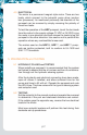
3. DESCRIPTION 3.1 GENERAL The Accu-Steer HRP05, HRP11 and HRP17 are complete pump assemblies each consisting of a reversing gerotor gear pump, hydraulic lock valves, suction make-up check valves, a valve housing manifold and an electric permanent magnet motor. FIGURE 3.1 HYDRAULIC SCHEMATIC 7 8 9 5 6 3 4 “A” “B” 2 DC MOTOR 1 Lines A and B are the output (port and starboard) lines, which are connected to steering lines on the vessel. Line T is the tank suction make-up or return line.
t Opening check valve (6) allows the returning oil from the steering cylinder to flow back to the pump. t If the pressure at the pump suction “B” is less than the pressure in the make-up line, oil from the make up line will pass by the check valve (4). This prevents cavitation due to any air that may be in the steering line. t When the pump stops turning all spring-loaded check valves return to the normally closed position.
t The shaft seal is accomplished using a rubber shaft seal rated at 50 psi. This shaft seal is connected to the tank/return line pump chamber. If this tank port is connected to a steering line or is over pressurized, it may cause this seal to fail. See the installation instructions for more details. 3.4 VALVE BLOCK and VALVES A list of features: t The valve block is an aluminum block, precision machined to house the valves, direct the oil and serve as the endplate for the gear pump.
Most steering manufacturers have recommended hydraulic oils to be used in their systems. The HRP pumpsets are compatible with these oils. Most manufacturers use an ISO #32 or ISO #10 type of oil. Three hydraulic connections are required to the pumpset. Two lines connect the pump (outputs A and B) to the main steering (port and starboard) lines.
4.3 ELECTRICAL The motor is a permanent magnet style motor. There are two leads, which connect to the autopilot pump driver junction box (processor). As mentioned previously the direction of the pumpset can be reversed by simply reversing the polarity of these two leads. To test the operation of the HRP pumpset, touch the two leads from the motor to the supply voltage (12 VDC or 24 VDC) to jog the motor in one direction and then reverse the leads to jog the pumpset in the other direction.
6. NOTES .................................................................................................................... .................................................................................................................... .................................................................................................................... .................................................................................................................... ...................................
7. DRAWINGS 7.1 HRP t HRP t HRP17 ASSEMBLY SCHEMATIC 4” SIDE VIEW 8” A 3.25” T TOP VIEW 4” B 2.
7.
8. CYLINDER-PUMP REFERENCE GUIDE Please read the following: t The Accu-Steer HRP series of pumps are recommended for medium duty applications (<100 hours/month). t The Accu-Steer HPU100 and up are recommended for heavy duty and work boat applications. t The Accu-Steer HM series of hydraulic manifolds require an electric driven or engine driven pump unit. t When 2 cylinders are used double the displacement volumes. STEERING MFR.
STEERING MFR. CYLINDER MODEL BORE/ STROKE CU IN DSPLT ACCU-STEER PUMP “A” HYNAUTIC K-27 1.50” x 10.00” 13.3 HRP11 JASTRAM MAROL ACCU-STEER PUMP “B” COMMENTS K-28 1.50” x 12.00” 16.0 HRP11 HRP17 K-29 1.50” x 12.00” 16.0 HRP11 HRP17 K-31 2.00” x 10.0” 25.5 HRP17 HRP75 K-32 2.00” x 8.00” 20.0 HRP17 HRP75 K-33 2.00” x 9.00” 23.1 HRP17 HRP75 K-51 1.50” x 7.00” 10.2 HRP11 B-125-7 1.25” x 7.00” 6.4 HRP05 INBOARD/OUTBOARD B-125-9 1.25” x 9.00” 8.
STEERING MFR. CYLINDER MODEL BORE/ STROKE CU IN DSPLT ACCU-STEER PUMP “A” MAROL MRB-50 N/A 3.7 HRP05 LEVER RATIO = 0.74 : 1.00 MRB-50 N/A 4.8 HRP05 LEVER RATIO = 1.00 : 1.00 MRB-63 N/A 5.1 HRP05 LEVER RATIO = 1.23 : 1.00 MRB-63 N/A 7.1 HRP05 LEVER RATIO = 1.00 : 1.00 MRB-63 N/A 9.3 HRP05 MRB-75 N/A 10.6 HRP11 LEVER RATIO = 0.74 : 1.00 MRB-75 N/A 14.7 HRP11 LEVER RATIO = 1.00 : 1.00 MRB-75 N/A 19.2 HRP17 LEVER RATIO = 1.23 : 1.00 MRB-80 N/A 18.
STEERING MFR. CYLINDER MODEL TELEFLEX WAGNER BORE/ STROKE CU IN DSPLT ACCU-STEER PUMP “A” ACCU-STEER PUMP “B” COMMENTS 125-8EM 8.4 / 9.8 HRP05 HRP11 UNBALANCED CYLINDER 125-8VEM 8.4 / 9.8 HRP05 HRP11 UNBALANCED CYLINDER 92-VPS 9.8 / 11.6 HRP05 HRP11 UNBALANCED CYLINDER BA125-7 1.25” x 7.00” 7.2 HRP05 BA125-8 1.25” x 8.00” 9.0 HRP05 BA135-7 1.35” x 7.00” 8.2 HRP05 BA135-8 1.35” x 8.00” 9.4 HRP05 BA150-7 1.50” x 7.00” 10.2 HRP11 BA175-7 1.75” x 7.00” 13.
STEERING MFR. CYLINDER MODEL BORE/ STROKE CU IN DSPLT ACCU-STEER PUMP “A” ACCU-STEER PUMP “B” COMMENTS WAGNER N400-1500 4.00” x 15.00” 152.4 HPU300 HM250 HEAVY DUTY APPLIC. N400-2000 4.00” x 20.00” 203.2 HM400 T2 N/A 16.0 HRP75 HPU100 HEAVY DUTY APPLIC. T3 N/A 20.4 HRP75 HPU100 HEAVY DUTY APPLIC. T4 N/A 30.5 HRP75 HPU100 HEAVY DUTY APPLIC. T5 N/A 41.6 HPU100 T10 N/A 54.2 HPU100 HPU200 HEAVY DUTY APPLIC. T11 N/A 54.2 HPU100 HPU200 HEAVY DUTY APPLIC.