
Operation Manual


3. DESCRIPTION
3.1 GENERAL
The Accu-Steer HRP05, HRP11 and HRP17 are complete
pump assemblies each consisting of a reversing gerotor gear
pump, hydraulic lock valves, suction make-up check valves,
a valve housing manifold and an electric permanent magnet
motor.
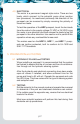
FIGURE 3.1 HYDRAULIC SCHEMATIC
Lines A and B are the output (port and starboard) lines, which
are connected to steering lines on the vessel. Line T is the tank
suction make-up or return line. These lines are clearly marked
on the valve housing. Do not connect the output lines to the
tank (T) port.
The HRP (Hydraulic Reversing Pumpset) operates as follows:
t As the motor (1) rotates CCW, oil from the gear pump (2) is
pumped towards output “A”.
t This oil passes through the check valve (5) and goes to the
line output (7).
t The pressure at output “A” ensures the check valve (3)
stays closed and manually opens check valve (6).
“A”
2
1
43
8
5
79
6
DC
MOTOR
“B”
p03