
Operator's Manual

31
Installation Procedures
Installation
IND100078-34
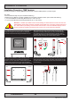
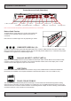
▼ 5: Ensure that both Key Hole Plugs slide into the Key Holes and goes to the bottom position (FIG1 and FIG2). If they appear
too tight, you may loose the Key Hole Plug screw a few turns and re-try (see previous step 2). FIG3 shows Key Hole Plug
correctly into Key Hole and both brackets in place.
FIG1
FIG2
FIG3
FIG3
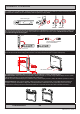
▼ 6: Tighten Key Hole Screw rmly on each side and
make sure the brackets are properly mounted and
aligned to the main chassis of unit. Verify with your
hands that both brackets are rmly attached.
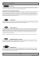
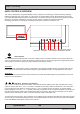
▼ 7: While unit is lying at on table, check the Tilting Lock Pin
position. These can be pulled out by hand, turned 90° (FIG1) and
turned back 90° until the Lock Pin automatically clicks into place by a
spring (FIG2).
FIG1
FIG2
Locked Unlocked
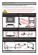
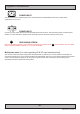
▼ 8: You may now mount the unit onto your desired location. It is advised that you unlock the Lock Pin (as shown in step 7), tilt
the unit 90 degrees backwards (FIG1) and properly fasten the bracket base into location (FIG2). NB! Be careful not to break
or scratch the edge of the front glass! Then repeat step 7 again until your desired tilting position has been achieved and you
have veried that the Lock Pin are in locking position and the unit is rmly attached and does not appear loose (FIG3).
Unlock, tilt and lock
FIG1
FIG2
Top View
Use appropriate fasteners
6 pcs x M6 needed
FIG3
Re-check Lock Pins!
Single Key hole units does not support ceiling mount.