
Operator's Manual

35
IND100133-48
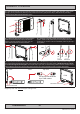
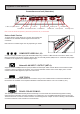
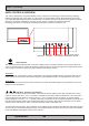
Connection area of unit (illustration)
Physical Connections
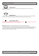
Reduce Cable Tension
To reduce tension of the cables you connect, secure them with
a cable tie to the available chassis hinges located near the
connectors.
Note: Amount of chassis hinges can vary depending on model.
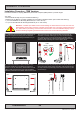
Grounding Screw
3 x BNC, Composite Video IN
Power Input DC
USB Touch
RJ45 Network 2 x VGA/RGB InRS-422/RS-485 COM
RS-232 COM
Potmeter Port
2 x DVI-D In
COMPOSITE VIDEO IN 1,2,3:
Connect a Composite Video signal (PAL/NTSC/SECAM) to any of these 3 x BNC female connectors to allow video
feed to be used as Full Screen, Picture-In-Picture (PIP) or Picture-By-Picture (PBP) from i.e. cameras & DVD players
in addition to the regular DVI or RGB/VGA signal input.
Network/LAN INPUT / OUTPUT (NET A):
Supports 10/100/1000Mbps Ethernet (LAN). Suitable for twisted pair cables CAT.5E. Make sure the network cable
connector ”clicks” into the RJ-45 connector. This connector will allow remote control of the display unit to control
common functions like brightness, input source and more.
USB TOUCH:
Connect a TYPE A USB Cable between this connector and your PC. Suitable drivers to install and calibrate the
touchscreen are available on the separate installation media delivered with the unit. Port is USB2.0 (<5m).
RS-422 / RS-485 COM I/O:
The COM (non-isolated RS-422/485) allows functionality to communicate with serial based equipment including
external buzzer functionality. Connect and fasten your cables from your compatible external equipment to the 5-pin
Terminal Block 3.81 connector. Please review the “Pinout Assignments” chapter as well as “Housing / Terminal Block
Connector Overview” in this manual for more information.
Note: 19 inch unit used as example above, please review specications for your actual model.
VGA/RGB Out
Power Input AC