
Operator's Manual

32
Installation Procedures
Installation
IND100078-34
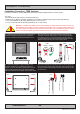
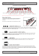
Installation Procedure - TMB Versions
Procedure suitable for: Display (MMD/STD) and Panel Computer (MMC) Series X product ranges.
You need:
- M4 Unbrako® Hex Key tool (not included with delivery).
- Fasteners (6 pcs M6) for mounting complete unit onto table or desktop location (not included with delivery).
- 1 pcs of HD TMB SX1-A1 Mounting Bracket Kit (for 12 and 15 inch)
- or 1 pcs of HD TMB SX1-B1 Mounting Bracket Kit (for 17 and 19 inch)
Attention: A suitable pre-drilled location and knowledge of measurements for both main unit and
brackets/tilting functionality should be prepared and checked prior to mounting. Please disconnect
ALL cables before proceeding. Please review User Manual or visit www.hatteland-display.com for
Technical Drawings regarding measurements for both main unit and Mounting Brackets.
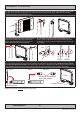
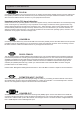
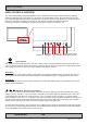
▼ 1: Place the unit on a dry, at, clean, soft surface (i.e.
table) with the glass front facing down as illustrated.
Connector area should be facing downwards from you.
▼ 2: Inspect the inner side of both brackets and especially the
orientation of the Key Hole Plug (4 pcs). They should be shaped
as an standing “egg” to ensure proper tting in the Key Hole of
unit (FIG1). Note: You may have to loose the fastening screw (M5)
(FIG2) if the Key Hole Plug can not be turned by hand.
Seen from
above
Connector Area
Wrong Correct
Adjust
FIG2
FIG1
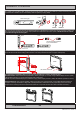
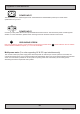
▼ 3: Notice the indication of LEFT and RIGHT. The
mounting bracket (2 pcs) is marked with respective
stickers “L” and “R” from factory. Please make sure that
LEFT bracket is positioned on LEFT side and RIGHT
bracket is positioned on the RIGHT side as shown below.
▼ 4: Ensure that both Key Hole Plugs slide into the Key Holes and
goes to the upper position (FIG1 and FIG2). If they appear too tight,
you may loose the Key Hole Plug screw a few turns and re-try (see
previous step 2).
LEFT RIGHT
FIG1
FIG2