
Operator's Manual

33
Installation Procedures
Installation
IND100078-34
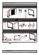
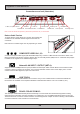
▼ 5: While unit is lying at on table, check the Tilting Lock Pin position. These can be pulled out by hand, turned 90° (FIG1) and
turned back 90° until the Lock Pin automatically clicks into place by a spring (FIG2).
FIG1
FIG2
Locked Unlocked
Glass Facing Up
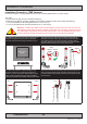
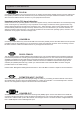
▼ 6: You may now mount the unit onto your desired location. It is advised that you unlock the Lock Pin (as shown in step 5), tilt
the unit 90 degrees backwards (FIG1) and properly fasten the bracket base into location (FIG2). NB! Be careful not to break
or scratch the edge of the front glass!
Unlock, tilt and lock
FIG1
FIG2
Top View
Use appropriate fasteners
6 pcs x M6 needed
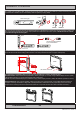
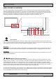
▼ 7: Max Forward and Backward angle shown below (FIG1). When your desired tilting position has been achieved, you need to
verify that the Lock Pin are in locking position and the unit is rmly attached and does not appear loose (FIG2).
FIG2
Re-check Lock Pins!
FIG1
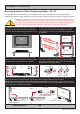
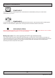
▼ 8: Depending on installation needs, you may mount the complete unit in ceiling in two different ways.
Normal Position: User Controls will be upside down, cables go straight up. You may congure Glass Display Control™ (GDC)
LED symbols to show or not, since symbols will be seen upside down.
Review http://www.hatteland-display.com/inb100018-4.php (“Glass Display Control™ (GDC) LED & Button operations” section).
Swapped Position: User Controls readable, cables has to bend up or go straight down, Left and Right Bracket needs to be
swapped, indicating Left Bracket on Right Side, and RIght Bracket on Left Side to ensure proper tting and to avoid wrong
footprint of the mounting holes of the bracket base (reference to “Important to know about LEFT and RIGHT brackets”).
Normal Position Swapped Position