
Operator's Manual
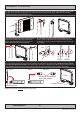
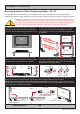
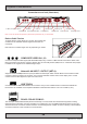

Physical Connections
36
IND100133-48
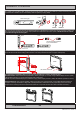
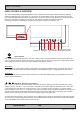
DVI-D IN:
Connect your DVI cable to any of the two DVI-D 18+1P, Single Link Connector (female). Secure your DVI cable to the
hex spacers provided on the unit and make sure you do not bend any of the pins inside the connector. Connect the
other end of the cable to the DVI connector on your equipment and secure it.
Important note for DVI signal detection:
Please note that for the operating system to detect DVI signals correctly, the DVI cable MUST be connected physically
to the unit during boot up otherwise you may experience a black image. Furthermore certain graphics drivers may
need to refresh their device list (often done manually by user - detect devices), while in some cases the Plug-n-Play
will automatically detect the DVI signal correctly. Please consult your local technician if you have this behaviour of
detection problems when using DVI. In all cases the problem can be solved in the operating system, and this is not a
malfunction in the graphic controller for display units.
VGA/RGB IN:
Connect your VGA cable to any of the two D-SUB 15P Connectors (female). Secure the VGA cable to the hex spacers
provided on the unit and make sure you do not bend any of the pins inside the connector when connecting. Connect
the other end of the cable to the VGA connector on your equipment and secure it.
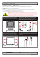
RS-232 COM I/O:
This 9P COM connector provides additional functionality for the unit. The Serial Remote Control features a RS-232
(non-isolanted) interface for controlling internal parameters like brightness. You can access most of the parameters
available in the OSD menu and with special commands control the unit externally. This COM can also be used to
upgrade the rmware for the graphic controller inside the unit which is available on request and through service
channels (for qualied personnell only). Fasten your external cable to the D-SUB 9P Male connector using the
provided screws on the cable housing.
Please review “Management Settings/Communication” in the “OSD Menu Functions” chapter for more information.
POTMETER INPUT / OUTPUT:
Allows for controlling Brightness of the displayed image on screen by connecting an external remote control to the
9P D-SUB (male) connector which has Potentiometer IN, +5VDC OUT and BRT +/- IN functionality built in. Review
also the “Pin Assignments” chapter in this manual for more information.
VGA/RGB OUT:
VGA/RGB OUT enables a direct clone of the incoming VGA (RGB1) signal. Connect the cable to the D-SUB 15P
Connector (female) and secure it to the hex spacers provided on the unit. Connect the other end to your equipment
and secure it. Note that DVI inputs is NOT cloned, even though if the DVI-I connector has been configured with the
DVI-I > RGB adapter to use a RGB signal as input.