
Operator's Manual


94
IND100241-13
Appendix
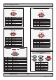
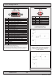
Pinout Assignments
2-pin DC Power Input,
1 2 3 A B
Pin 2: Negative - Pin 1: Positive +
ID’s (1,2,3,A,B,C) denotes where connector is (by factory default) or may be available (through factory customization).
Note that some combinations may not be possible due to space restrictions. List also valid for customized models.
All pin out assignments are seen from users Point of View (POV) while looking straight at the connector. Please review
the dedicated datasheet or technical drawings for your actual unit to identify and determine the presence of desired
connector. Detailed information about Housing Connectors (terminal blocks) can be found earlier in this manual.
1 Available for MMD (Maritime Multi Displays) units.
2 Available for STD (Industrial Standard Displays) units.
3 Available for MMC (Maritime Multi Computers / Panel Computers) units and/or Maritime Stand-Alone Computers (Compact, Fanless, Rack).
A For 8 / 13 inch sizes only
B For 12 / 15 / 17 / 19 / 24 / 26 inch sizes only
C Factory Option: For Maritime Stand-Alone Computers units only.
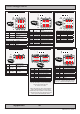
1-pin RCA/BNC COMP. VIDEO Female
1 B
Ground Shield
Pin 1: Video Signal
5-pin PS/2 KEYBOARD Female
3 B
Pin 1: Keyboard Data
Pin 3: Ground
Pin 5: Keyboard Clock
Pin 2: Not Connected
Pin 4: Vcc +5V
Pin 6: Not Connected
5-pin PS/2 MOUSE Female
3 B
Pin 1: Mouse Data
Pin 3: Ground
Pin 5: Mouse Clock
Pin 2: Not Connected
Pin 4: Vcc +5V
Pin 6: Not Connected
4-pin USB TYPE B
2 A B
Pin 2: Negative Data
Pin 3: Positive Data
Pin 4: Ground
Pin 1: VCC +5V
4-pin USB TYPE A
1 3 A B
Pin 2: Negative Data
Pin 1: VCC +5V
Pin 3: Positive Data
Pin 4: Ground
8-pin RJ45 10/100/1000mbps LAN/Ethernet
1 3 A B
1 2 3 4 5 6 7 8
PIN 01 D0P+ Differential Pair 0 (Positive)
PIN 02 D0N- Differential Pair 0 (Negative)
PIN 03 D1P+ Differential Pair 1 (Positive)
PIN 04 D2P+ Differential Pair 2 (Positive)
PIN 05 D2N- Differential Pair 2 (Negative)
PIN 06 D1N- Differential Pair 1 (Negative)
PIN 07 D3P+ Differential Pair 3 (Positive)
PIN 08 D3N- Differential Pair 3 (Negative)
9-pin Amplied Mono/Stereo Audio Out, DSUB Female
Type Number “HT 00235 OPT-A1”
3 B
5 4 3 2 1
9 8 7 6
PIN 01 LAUDR Left Audio Return*
PIN 02 LAUD Left Audio*
PIN 03 RAUDR Right Audio Return
PIN 04 RAUD Right Audio
PIN 05 N/C No internal connection
PIN 06 N/C No internal connection
PIN 07 N/C No internal connection
PIN 08 N/C No internal connection
PIN 09 N/C No internal connection
*For Mono: connect pin 01 and 02 only