Back Installation Manual MARINE RADAR MODEL1724C/1734C COLOR VIDEO PLOTTER GD-1720C SAFETY INSTRUCTIONS ................................................................................................ i EQUIPMENT LISTS......................................................................................................... ii SYSTEM CONFIGURATIONS ........................................................................................ iv 1. MOUNTING ..........................................................
The paper used in this manual is elemental chlorine free. ・FURUNO Authorized Distributor/Dealer 9-52 Ashihara-cho, Nishinomiya, 662-8580, JAPAN Telephone : +81-(0)798-65-2111 Fax : +81-(0)798-65-4200 All rights reserved. Printed in Japan A : APR . 2005 E : JUL . 16, 2009 Pub. No.
SAFETY INSTRUCTIONS WARNING WARNING Radio Frequency Radiation Hazard Do not open the equipment unless totally familiar with electrical circuits and service manual. The radar antenna emits electromagnetic radio frequency (RF) energy which can be harmful, particularly to your eyes. Never look directly into the antenna aperture from a close distance while the radar is in operation or expose yourself to the transmitting antenna at a close distance. Only qualified personnel should work inside the equipment.
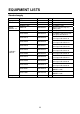
EQUIPMENT LISTS Standard supply Name Display unit Antenna unit Remote controller set Installation materials Type RDP-148 RSB-110-070-A RSB-0071-058 Code No.
Optional supply Name Rectifier PR-62 External buzzer OP03-136 Code No.
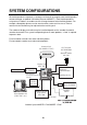
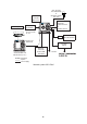
SYSTEM CONFIGURATIONS All NavNet products incorporate a “network circuit board” to integrate each NavNet product on board through an optional LAN cable (Ethernet 10BASE-T). Each NavNet product is assigned an IP address to enable transfer of images between other NavNet products. For example, video plotter pictures can be transferred to a radar and vice versa. Pictures received via the NavNet may be adjusted at the receiving end.
GPS receiver GP-320B/330B or Weather station WS-200 Remote Controller RMC-100 AIS transponder Echo sounder* Navigator* External buzzer PC Heading sensor AIS Interface IF-1500AIS* * Not required for AIS Transponder FA-150. * NMEA sentence only HUB FA-30 AIS RECEIVER Display unit RDP-148 Rectifier PR-62 Other NavNet Unit (Model 1724C, etc.
GP-320B/330B, WS-200 Antenna Unit Radar data Plotter data HUB Sounder data Network Sounder ETR-6/10N ETR-30N (option) Note: The picture disappears 10 seconds after the NavNet cable is disconnected from a "sub" NavNet display unit.
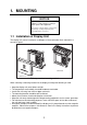
1. MOUNTING NOTICE Do not apply paint, anti-corrosive sealant or contact spray to coating or plastic parts of the equipment. Those items contain organic solvents that can damage coating and plastic parts, especially plastic connectors. 1.1 Installation of Display Unit The display unit can be installed on a tabletop, on the overhead or flush mounted in a console or panel.
1.1.1 Mounting procedure Tabletop, overhead mounting Follow the procedure below to mount the display unit on a tabletop or the overhead. 1. Fix the hanger by four tapping screw. 2. Screw knob bolts in display unit, set it to hanger, and tighten knob bolts. 3. Attach hard cover to protect LCD. Display unit Tapping screws (4 pcs.) Knob bolts (2 pcs.
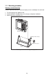
Flush mounting Note: Use supplied pan head screws when the thickness of the bulkhead is from 11 to 14 mm. For bulkhead which exceeds 14 mm in thickness the length of the pan head screws should be bulkhead thickness (A) plus 7.3±1.5 mm. Also the length of B should be max. 7 mm. B A Fixing screw, side view 1. Prepare a cutout in the mounting location whose dimensions are as shown in below. 2. Attach the flush mount sponge to the display unit. 3. Fix the display unit by six washer head screws M4x20.
1.2 Mounting of Antenna Units 1.2.1 Mounting considerations When selecting a mounting location for the antenna unit keep in mind the following points. • Install the antenna unit on the hardtop, radar arch or on a mast on an appropriate platform. (For sailboats, a mounting bracket is optionally available.) It should be placed where there is a good all-round view with, as far as possible, no part of the ship's superstructure or rigging intercepting the scanning beam.
1.2.2 Mounting antenna unit of MODEL 1724C 1. Remove mounting hardware at the bottom of the antenna unit; four each of hex bolts (M10X20), spring washers and flat washers. Save the spring washers and flat washers to use them to fix the radome base to the platform, at step 3. If the thickness of the mounting platform is 5 mm or less also save the bolts.
4. Unfasten four screws to remove the cover. Discard the packing material in the radome. Snap holder Remove and discard the packing material. Antenna unit, inside view The mounting base is fitted with a snap holder, which may be used to hang the cover after removal. Use the hole next to screw hole inside the cover to hang it. a) Unfasten the snap assy. with the string attached at the holder in the mounting base. b) Unwind the string. c) Attach the snap to a screw hole on the inside of the cover.
5. Unfasten the cable of the rotation detector from the cable clamps. 6. Unfasten 11 screws to dismount the shield plate. Discard screw marked with figure shown below. in the Cable clamp Shield plate Rotation detector Caution Antenna unit, inside view Caution: Be careful not to pinch the rotation detector cable when remounting the shield plate. 7. Pass the antenna cable with connector through the gasket and cable clamp, and then tighten cable gland.
Rubber gasket Gasket Cable Gland Sectional view Rubber gasket Mounting base Antenna unit, inside view 8. Referring to the figure shown below, fasten the shield cable with screw (M4x10) on the chassis to ground the unit. Connect 10 pin connector here (J811). Connect shield cable here. Connect 9 pin connector here (J801).
9. Attach EMI core (supplied) to antenna cable between cable ties. Set the fixing band to the EMI core. Fixing band This bend should be facing cable entry. Fixing band 10. Referring to the figure of "How to connect the antenna cable to the antenna Unit" on the previous page connect the 9-pin (J801) and 10-pin (J811) connectors of the antenna cable to the INT Board. 11. Refasten the shield plate with 10 screws. Be sure not to pinch cable from the rotation detector with the shield plate.
1.2.3 Mounting antenna unit of MODEL 1734C 1. Open the antenna unit packing box carefully. 2. Unbolt the four bolts at the base of the radome to remove the radome cover. Radome cover Antenna unit The mounting surface must be parallel with the waterline and provided with five holes (four fixing holes and one cable entry) whose dimensions are shown in the outline drawing attached at the end of this manual.
Antenna base plate Effective thread length Gasket Radome 25 mm 5 - 10 mm Flat washer Spring washer Apply silicone sealant. Platform M10 x 25 Hex bolt How to fasten the radome base to the mounting platform Wiring and final preparation 4. Drill a hole of at least 20 millimeters diameter through the deck or bulkhead to run the signal cable between the antenna unit and the display unit.
to one of the screws of the cable clamping plate 9-pin connector: to J801 on MD-9208 4-pin connector: to J802 on MD-9208 13-pin connector: to J611 on IF-9215 Signal cable, antenna unit side J802 J801 J611 RF unit 12
10. Attach the EMC core supplied as shown below. J801 J802 J805 MD9208 J804 J806 J803 Cable entrance Cable clamping plate Motor EMC core E04SS251512 (Above cable clamping plate) J1 J613 PTU-9335 J611 IF9215 How to attach EMC core 11. Fix the shield cover. Do not pinch the cable. 12. Attach the radome cover, aligning triangle mark on radome cover with that on radome base. Radome cover Radome base How to position the radome cover 13. Loosely fasten the radome fixing bolts.
1.2.4 Mounting the optional mounting bracket A mounting bracket for fastening the antenna unit to a mast on a sailboat is optionally available. Mounting bracket 1 (for MODEL 1734C) Type: OP03-92 Code No.: 008-445-070 Part Type Code No. Qty Hex. bolt M4X12 000-804-725 4 Hex.
Support plate (A) Assembling the mounting bracket (B) Fastening antenna to mounting bracket How to assemble and mount the optional mounting bracket 15
2. WIRING 2.1 Standard Wiring All wirings are terminated at the rear of the display unit. CAUTION The power cable is shipped with a 10A fuse (5A on GD-1720C) inserted in its fuse holder. This fuse is for use with a 12 VDC power supply. If you are using a 24 VDC power supply, replace the fuse with a 5A fuse (3A fuse on GD-1720C). Also, attach the "5A label" ("3A label" on GD-1720C) to the fuse holder on the power cable. Use of an improper fuse can result in damage to the equipment.
Signal cable connection 1. Remove the waterproofing cover from the DJ-1 at the back of the display unit. 2. Connect the signal cable to DJ-1 on the rear panel of the display unit. Rubber cover DJ Connector Cable Boot-band DJ-1 Display unit 3. Cover the connector with the rubber cover. 4. Put the boot-band as shown above, and fasten four screws to fix. Note: When the display unit is used without signal cable connection, do not remove the waterproofing cover.
DATA1 to DATA3 ports These ports connect to the equipment shown in the table below. DATA1 (7P) DATA2 (6P) DATA3 (7P) GPS receiver GP-310B/320B, Heading sensor RS-232C OUT, NMEA 0183 IN, NMEA equipment (ex. SC-60/120) External buzzer OUT Note: No sensor can be directly connected to the DATA3 port. This equipment can receive the following NMEA 0183 format sentences from other equipment.
2.2 External Buzzer (OP03-136, option) Connection The optional external buzzer provides a louder alert when the guard alarm is violated. External buzzer Type: OP03-136 Code no.: 000-086-443 Further, you need the optional cable assy MJ-A7SPF0007-050C (w/7P connector, 5 m, code no. 000-154-028-10). 1. Attach the MJ-A7SPF0007-050C cable assy (option) to the DATA 3 port at the rear of the display unit. 2. Cut the XH connector at the end of external buzzer cable with appropriate length. 3.
2.3 How to Connect with a PC When connecting with the personal computer, prepare the optional cable assy MJ-A7SPF0007-050C and D-sub 9 pins plug (local supply), and connected them as follows. This function is not available with the GD-1720C.
3. SETTING UP THE EQUIPMENT 3.1 Setting up with the Installation Wizard After you have installed the equipment, set up the equipment with the installation wizard. The wizard allows you to easily set up the NavNet network (choose source of radar, sounder and auxiliary), GPS, ports, etc. 1. Press the POWER/BRILL key to turn on the power, and the following screen appears.
CAUTION: Ensure that the settings to be loaded are compatible with this NavNet unit. Improper settings will damage the equipment. 7. The screen for set up of units of measurement appears. RANGE UNIT nm, kt DEPTH UNIT ft TEMPERATURE UNIT °F WIND UNIT kt LOCAL TIME OFFSET +00:00 AIR PRESSURE UNIT hpa Installation wizard, units of measurement 8. Choose an item and then press the EDIT soft key. One of the following windows appears.
11. Choose DEVICE NUMBER, RADAR SOURCE or SOUNDER SOURCE as appropriate and then press the EDIT soft key. One of the following displays appears depending on your selection. RADAR SOURCE DEVICE NUMBER ▲ ▲ { { 1 (IP:172.031.003.001) ~ 2 (IP:172.031.003.002) { 3 (IP:172.031.003.003) { 4 (IP:172.031.003.004) ▼ SOUNDER SOURCE ▲ { ~ { { { { { { { { { 1 (IP:172.031.003.001) ~ 2 (IP:172.031.003.002) { 3 (IP:172.031.003.003) { 4 (IP:172.031.003.004) { NO CONNECT ▼ ▼ ETR0 (IP:172.031.092.001) ETR1 (IP:172.
13. After choosing ALL sources, press the NEXT soft key, and the RADAR SETUP menu appears. If you do not have a radar installed, press the NEXT soft key to show the NAV SETUP menu and go to step 25. ANTENNA TYPE A HEADING DATA MAGNETIC ANTENNA ROTATION ROTATE TUNING OFF TIMING ADJUST OFF HEADING ADJUST OFF Installation wizard, radar setup 14. Choose ANTENNA TYPE and then press the EDIT soft key. ANTENNA TYPE ▲ { ~ ▼ A (MODEL 1724C) B (MODEL 1734C) 15.
20. Choose TUNING and then press the EDIT soft key. TUNING ▲ { ~ ON OFF ▼ 21. Choose ON and then press the ENTER soft key. Then, the radar’s video and tuning are automatically adjusted. 22. After tuning has been completed, choose TIMING ADJUST and then press the EDIT soft key. TIMING ADJUST ▲ { ~ ON OFF ▼ This adjustment ensures proper radar performance, especially on short ranges. The radar measures the time required for a transmitted echo to travel to the target and return to the source.
23. Choose HEADING ADJUST and then press the EDIT soft key. HEADING ADJUST ▲ { ~ ON OFF ▼ 24. Choose ON and then press the ENTER soft key. You have mounted the antenna unit facing straight ahead in the direction of the bow. Therefore, a small but conspicuous target dead ahead visually should appear on the heading line (zero degrees). In practice, you will probably observe some small error on the display because of the difficulty in achieving accurate initial positioning of the antenna unit.
NAV SETUP menu description Item Position Source Description Chooses source of position data. Speed (STW) Source Temperature Source Chooses source of speed data Depth Source Chooses source of depth data. STW Calibration Temp Calibration Depth Calibration Wind Averaging Calibrates NMEA speed data. Enter amount in percentage. Calibrates NMEA temperature data. Enter offset to correct NMEA temperature data. Calibrates NMEA depth data. Enter offset to correct NMEA depth data.
28. After setting up navigation equipment, press the NEXT soft key, and the GPS SETUP menu appears. This menu sets ups the FURUNO GPS receiver GP-320B/330B. If you do not have this equipment, press the NEXT soft key and go to step 31. GEODETIC DATUM WGS-84 POSITION SMOOTHING 000 second (s) SPD/CSE SMOOTHING 005 second (s) LATITUDE OFFSET 0.000'N LONGITUDE OFFSET 0.000'E DISABLE SATELLITE -- -- -LATITUDE 45°35.000'N LONGITUDE 125°00.
GPS SETUP menu description (con’t from previous page) Item Description Settings Default Setting During position fixing, ship’s velocity (speed and course) is directly measured by receiving GPS satellite signals. The raw velocity data may change randomly depending on receiving conditions and other factors. You can reduce this random variation by increasing the smoothing. Like with latitude and longitude smoothing, the higher the speed and course smoothing the more smoothed the raw data.
GPS SETUP menu description (con’t from previous page) Item Fix Mode Cold Start Description Choose position fixing method: 2D (three satellites in view), 2D/3D (three or four satellites in view whichever is greater). Clears the Almanac to receive the latest Almanac. Settings 2D, 2D/3D Default Setting 2D/3D No, Yes No WAAS setup Press the WAAS SETUP soft key at the GPS SETUP menu to show the WAAS SETUP display.
32. Choose item and press the EDIT soft key. Choose appropriate setting and then press the ENTER soft key. Refer to the table and sentence description on the next page for details. 33. Press the NEXT key, and the DATA3 (PC/NMEA/EXT BUZZ) port setup menu appears. Set up this port similar to how you set up the DATA1 port. NMEA OUTPUT FORMAT NMEA Ver 2.
$GPGLL,3415.2345,N,13520.5301,E,152500.00 ,A*E7$GPGLL,3415.2345,N,135 20.5301,E,152500.00,A*E7$GPGLL ,3415.2345,N,13520.5301,E,152500.00,A* E7$GPGLL,3415.2345,N,13520.530 1,E,152500.00,A*E7$GPGLL,3415. 2345,N,13520.5301,E,152500.00,A*E7 $GPGLL,3415.2345,N,13520.5301,E,15 2500.00,A*E7
3.2 Checking Magnetron Heater Voltage Magnetron heater voltage is formed on the PTU or MD Board of the antenna unit, and preadjusted at the factory. Therefore, no adjustment is required. However, check magnetron heater voltage for confirmation as follows. This procedure should only be performed by a qualified technician. NOTICE For MODEL1724C, lift the radome cover slowly. Screw holes (4 places) The antenna radiator may be caught by the screw holes in the radome cover.
3.3 Remote Controller Setting A remote controller can be set exclusively for use with a specific display unit, in the case of multiple NavNet display units. Set the remote controller ID mode desired on the menu and attach appropriate label (supplied with accessories) to the remote controller and display unit. 1. Press the MENU key followed by the SYSTEM CONFIGURATION and GENERAL SETUP soft key to show the GENERAL SETUP menu.
0#/' +056#..#6+10 /#6'4+#.
0 # / ' 1 7 6 . + 0 ' 0 # / ' 1 7 6 . + 0 ' / 575 ޓ / 575 / 575 / 575 / : 575 ' 55 %2 45$ &'5%4+26+10 %1&' ͳ 3 6; #2 : #- : 䋨⇛࿑䈱ኸᴺ䈲䇮ෳ⠨୯䈪䈜䇯㩷㩷㪛㪠㪤㪜㪥㪪㪠㪦㪥㪪㩷㪠㪥㩷㪛㪩㪘㪮㪠㪥㪞㩷㪝㪦㪩㩷㪩㪜㪝㪜㪩㪜㪥㪚㪜㩷㪦㪥㪣㪰㪅䋩 #06'00# 70+6 +056#..#6+10 /#6'4+#.
A-4 5+)0#. %#$.' #55; ାภ㩃㨺㩖㩨㩣⚵ຠ 5+)0#. %#$.' #55; ାภ㩃㨺㩖㩨㩣⚵ຠ 5+)0#. %#$.' #55; ାภ㩃㨺㩖㩨㩣⚵ຠ 5+)0#. %#$.' #55; ାภ㩃㨺㩖㩨㩣⚵ຠ ฬޓޓ⒓ 0#/' ⇛ޓޓ࿑ 176.+0' /1&'. % % %1&' 01 5 %1&' 01 5 %1&' 01 5 %1&' 01 5 ဳฬ㧛ⷙᩰ &'5%4+26+105 ᢙ㊂ 3 6; ㆬᛯ 61 $' 5'.'%6'& ㆬᛯ 61 $' 5'.'%6'& ㆬᛯ 61 $' 5'.'%6'& ㆬᛯ 61 $' 5'.
9#5*'4 *'#& 5%4'9 $ 㩏㩗㩨㩈㩛㩇$ 9#5*'4 *'#& 5%4'9 㩏㩗㩨㩈㩛㩇$ 5'.( 6#22+0) 5%4'9 㩎㩡㩇㩊㨹㩕㩩㩧㩒㩆㩨 ޓ㩆㨷 (.75* /1706+0) 5210)' (㩙㨽㩧㩎㩠㨽㩇㩘㩩㩧㩆㩨 (75' .#$'. 㩕㨷㨺㩇㩨㩔㩢㩙㨺㩂 ฬޓޓ⒓ 0#/' ⇛ޓޓ࿑ 176.
Y.
Y.
Y.
D-4 Y.
% $ # 6& * 6& % )0& 4& 5& O ࠕࠞ 4'& ࠢࡠ $.- /, # 52( O Ǿ ࠪࡠ ࠕࠝ ࠠ 㩚㩎㩨㩢 ࠕࠞ ࠢࡠ /, # 52( O Ǿ /, # 52( Ǿ ᄖㇱⵝ⟎ ':6 '37+2/'06 /#: O )& % '64 0 /, # 54/& 6/ #2 /, # 52( *7$ 5 O ᄖㇱࡉࠩ 12 ':6 $7<<'4 㝼⟲ត⍮ᯏ 0/'# '%*1 5170&'4 ࡄ࠰ࠦࡦ 2% 45 % ࡋ࠺ࠖࡦࠣࡦࠨ *'#&+0) 5'0514 2) /, # 52( O Ǿ ࠪࡠ 9*6 ࠢࡠ $.ࠠ ;'. 㩚㩎㩨㩢 )40 #+5 (# +( #+5 ߹ߚߪ 14 O 016' 5*+2;#4& 5722.; 126+10 %100'%614 2.7) (+66'& #6 (#%614; 5*+'.& 5*17.
% $ # 6& * 6& % )0& 4& 5& O ࠕࠞ 4'& ࠢࡠ $.- /, # 52( O Ǿ ࠪࡠ ࠕࠝ ࠠ 㩚㩎㩨㩢 ࠕࠞ ࠢࡠ /, # 52( O Ǿ /, # 52( O Ǿ ࠪࡠ 9*6 ࠢࡠ $.ࠠ ;'. 㩚㩎㩨㩢 )40 /, # 52( Ǿ ᄖㇱⵝ⟎ ':6 '37+2/'06 /#: O )& % '64 0 /, # 54/& 6/ #2 /, # 52( *7$ 5 O ᄖㇱࡉࠩ 12 ':6 $7<<'4 㝼⟲ត⍮ᯏ 0/'# '%*1 5170&'4 ࡄ࠰ࠦࡦ 2% 45 % ࡋ࠺ࠖࡦࠣࡦࠨ *'#&+0) 5'0514 2) 016' 5*+2;#4& 5722.; 126+10 %100'%614 2.7) (+66'& #6 (#%614; 5*+'.& 5*17.& $' '(('%6+8'.
S-3 /, # 52( % O &2;% ᢛᵹེ 8#% 4'%6+(+'4 24 Ǿ *\ (75' # 8 /, # 52( # 8 ࠪࡠ 9*6 ࠢࡠ $. 8&% # )25ฃାᯏ )25 4'%'+8'4 )2 $ $ )0& +8 US ߹ߚߪ 14 #+5 (# +( #+5 ㆬᛯ 5'.'%6 $ #&ࠦࡦࡃ࠲ 0* 2 # & �# * %108'46'4 �# % #& 5*+(6 * 5*+(6 % 5) /, # 52( O Ǿ ࠪࡠ 9*6 ࠢࡠ $.ࠠ ;'. 㩚㩎㩨㩢 )40 ࡋ࠺ࠖࡦࠣࡦࠨ *'#&+0) 5'0514 2) /, # 52( O Ǿ )0& 4& 5& ࡄ࠰ࠦࡦ 2% 45 % ㆬᛯ 5'.