Installation Manual AUTOPILOT Model NAVpilot-700/711/720/711C SYSTEM CONFIGURATION ......................... ii EQUIPMENT LISTS...................................... iii 1. HOW TO INSTALL THE UNITS ............ 1-1 1.1 Control Unit FAP-7001/FAP-7011 ...... 1-1 1.1.1 Surface mount .......................... 1-2 1.1.2 Desktop mount ......................... 1-4 1.2 Processor Unit FAP-7002 ................... 1-5 1.3 Rudder Reference Unit FAP-6112...... 1-7 1.4 Remote Controllers (option)................
The paper used in this manual is elemental chlorine free. ・FURUNO Authorized Distributor/Dealer 9-52 Ashihara-cho, Nishinomiya, 662-8580, JAPAN All rights reserved. Printed in Japan A : JAN . 2010 J : OCT . 24, 2013 Pub. No.
SAFETY INSTRUCTIONS Please read these safety instructions before you install the equipment. WARNING CAUTION Indicates a condition that can cause death or serious injury if not avoided. Indicates a condition that can cause minor or moderate injury if not avoided. Warning, Caution Mandatory Action Prohibitive Action WARNING CAUTION Turn off the power at the switchboard before beginning the installation. Confirm that the power supply voltage is compatible with the voltage rating of the equipment.
SYSTEM CONFIGURATION CONTROL UNIT FAP-7001 CONTROL UNIT CONTROL UNIT FAP-7011C FAP-7011 JUNCTION BOX FAP-7822 CONTROL UNIT QTY FAP-7001/7011: MAX. 6*1 FAP-7021: MAX.
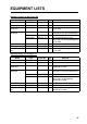
EQUIPMENT LISTS Standard supply for NAVpilot-700 Name Control Unit Processor Unit Rudder Reference Unit Installation Materials Spare Parts Accessories VOLVO Interfece Kit Type Code No. Qty FAP-7001 FAP-7002 FAP-6112-200 - 1 1 1 CP64-02900 000-016-414 1 CP64-03101 CP64-02601 001-082-720 009-001-170 1 1 SP64-01501 FP64-01401 FAP-6300 001-082-710 001-082-700 000-022-971 1 1 1 Type Code No.
Standard supply for NAVpilot-720 Name Control Unit Processor Unit Rudder Reference Unit Installation Materials Spare Parts Accessories Type FAP-7021 FAP-7002 FAP-6112-200 CP64-03101 CP64-02601 SP64-01501 FP64-01411 Code No. Qty Remarks - 1 1 1 w/20 m cable 001-082-720 009-001-170 001-082-710 001-082-770 1 1 1 1 For Processor Unit For Rudder Reference Unit For Processor Unit, fuse For Control Unit Code No.
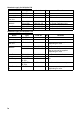
Optional supply Name Type Control Unit FAP-7001 FAP-7011 FAP-7021 FAP-7011C Remote FAP-5551 Controller FAP-5552 FAP-6211 FAP-6212 FAP-6221 - FAP-6222 - FAP-6231 FAP-6232 FAP-6300 000-022-971 VOLVO Interface Kit IPS InterIF-700IPS face unit VOLVO IPS AUTOPILOT-GATEWAY Gateway Distributor FAP-6800 Terminator BD-07AFFM-LR7001 Cable Assy MJ-A10SPF0001-060+ MJ-A10SPF0001-120+ BD-07AFFM-LR-100 T-type Connector Code No. Remarks Max. 5 optional units Max. 5 optional units Max. 2 optional units Max.
Name Type Termination LTWMC-05BMMT-SL8001 Resistor LTWMN-05AMMT-SL8001 LTWMC-05BFFT-SL8001 LTWMN-05AFFT-SL8001 Cable FAP-7822 Extension Kit Cradle FP64-01411 Flush FAP-7001-FLUSH-KIT Mount Kit FAP-7011-FLUSH-KIT Bracket FAP-7001-BRACKET FAP-7011-BRACKET Rudder Reference Unit Junction Box Bracket Assembly Flush Mount Kit Code No.
1. HOW TO INSTALL THE UNITS Note: For how to install the Control Unit FAP-7011C, see the operator’s manual (OME72780). 1.1 Control Unit FAP-7001/FAP-7011 • The Control Unit can be installed three ways: • Surface mount (fixed from front panel or fixed from rear panel (FAP-7011 only)) • Desktop mount, and • Flush mount (Optional kit required, instructions, supplied separately). Control Unit-FAP-7001 Control Unit FAP-7011 Select a mounting location for the Control Unit, keeping the following in mind.
1. INSTALLATION 1.1.1 Surface mount There are two types of surface mounts: Fasten from front panel and fasten from rear panel (FAP-7011 only). How to fasten Control Unit from front panel (FAP-7001/FAP-7011) 1. Using the surface mount template at the back of this manual, open a mounting hole in the installation site. 2. Detach the front panel together with the keypad assy. Attach the sponge (supplied) to the rear of display unit. 3.
1. INSTALLATION How to fasten Control Unit from rear panel (FAP-7011 only) 1. Using the surface mount template at the back of this manual, open a mounting hole in the installation site. 2. Set studs (M3x40, 2 pcs, supplied) in the holes marked in the illustration below. (Use only the studs supplied.) Insert stud here. 3. Set the unit to the mounting hole. Fasten the unit with the flat washers, spring washers and wing nuts (supplied).
1. INSTALLATION 1.1.2 Desktop mount Use the optional bracket installation kit to install the Control Unit on a desktop or the overhead. Bracket installation kit for FAP-7001 Type: FAP-7001-BRACKET, Code No.: 001-082-750 Name Bracket Connecting plate Knob Self-tapping screw Pan head screw Liner Type 64-028-1201-1 64-028-1201-1 64-028-1203-0 4x16 M3x12 64-026-1033 Code No.
1. INSTALLATION 6. Attach the hard cover to protect the LCD. Connecting plate Pan head screw (M3x12, supplied) Self-tapping screw (4x16, supplied) Liner Knob Bracket 1.2 Processor Unit FAP-7002 This unit can be installed on a desktop or on a bulkhead. Select a mounting location considering the following points: • Install the unit away from direct sunlight and water splash. • Select a location where temperature and humidity are moderate and stable.
1. INSTALLATION • Make sure there are no objects near the vent. • Leave enough space around the unit for maintenance and servicing. The recommended maintenance space appears in the outline drawing at the back of this manual. • Observe the compass safe distances shown in the safety instructions on page i to prevent interference to a magnetic compass. Install the unit as follows: Tabletop: Fasten with four self-tapping screws. Bulkhead: Screw in two self-tapping screws for the upper side.
1. INSTALLATION 1.3 Rudder Reference Unit FAP-6112 Note 1: This unit is not required for Fantum FeedbackTM. For details of Fantum FeedbackTM, see “Fantum FeedbackTM“ (page 1-8). • Leave sufficient space around all moving parts. • The unit must be fastened to the rudder as shown below, where the following conditions are met: 350 mm(13.8”)
1. INSTALLATION Relationship between reversing pump flow rate and steering cylinder capacity The table below shows a rough guideline to determine the proper reversing pump flow rate to match with the hydraulic steering cylinder capacity. Your experience with specific boat designs may cause you to select a pump/cylinder relationship outside of the range of these guidelines. Pump spec. 1.0 cu. in./sec. pump 1.6 cu. in./sec. pump Hardover to Hardover is 70° 5.85 to 17.5 cu. in. 9.36 to 28.0 cu. in.
1. INSTALLATION 1.4 Remote Controllers (option) Two remote controllers may be connected to the Processor Unit. To connect three NFU(Non-Follow Up) type remote controllers (button and lever) to the Processor Unit, connect them via the optional Distributor FAP-6800. Keep the remote controllers away from areas subject to rain and water splash. Note: For Fantum FeedbackTM, the remote controller can not be connected. Dial-type remote controller FAP-5551/FAP-5552 Fasten these remote controllers to a bulkhead.
1. INSTALLATION Button-type remote controller FAP-6211/6222 48 (1.9”) 135 (5.3”) 62 (2.44”) Lever-type remote controller FAP-6221/6222 Allow sufficient space around the unit for maintenance. 82.5-87.5 (3.24”-3.44”) 16 (0.63”) 140 (5.51”) 115 (4.52”) 100 (3.94”) 132 (5.2”) 100 (3.94”) 132 (5.2”) 16 (0.63”) 140 (5.51”) To mount the FAP-6221/6212 in a panel, the optional flush mount kit OP64-4 or OP64-5 is required. Flush mount kit OP64-4 (Code no. 009-005-790) Name Panel frame Rubber ring Hex.
1. INSTALLATION Flush mount kit OP64-5 (Code no. 009-005-800) Name Fixing plate Rubber ring Hex. nut Spring washer Hex. bolt Type OP64-5 64-015-4524 M4 M4 M4x35 Code No. 009-006-200 100-145-111-10 000-167-488-10 000-167-405-10 000-162-861-10 Qty 1 1 4 4 4 6.5 0.26” 150 (5.9”) 137 (5.4”) MAX.25(0.98”) 147 (5.8”) 150 (5.9”) Hex. nut Spring washer 1.5 Flat washer (0.06”) Panel frame Rubber ring 140 (5.
1. INSTALLATION Hex. nut Spring washer Hex. bolt Rubber ring Pan head screw M3x20 (local supply) Fixing plate 135 (5.3”) MAX.25(0.98”) 135 (5.3”) How to flush mount the FAP-6221 with flush mount kit OP64-5 1.5 Distributor FAP-6800 (option) Use the Distributor to connect three Non-Follow Up-type remote controllers to the Processor Unit. Fix the unit to the mounting location with wood screws. For added support, use nuts, bolts and washers (all local supply) instead of the wood screws. 60(2.36”) 37(1.
1. INSTALLATION 1.6 Control Unit FAP-7021 The Handheld Control Unit FAP-7021 can be mounted on the bulkhead or desktop using the cradle. When selecting a location for the Control Unit, keep the following in mind. • Mount the unit where shock and vibration are minimal. • Do not install the display unit under "Plexiglas" or other type of shielding material. Plexiglas can trap heat and moisture or magnify sunlight energy onto the surface of the display.
1. INSTALLATION This page is intentionally left blank.
2. WIRING 2.1 General Wiring All units are connected to the Processor Unit. Separate the cables as far as possible from the cables that transmit radio frequency or pulsed signals. At least one meter separation is recommended.
2. WIRING 2.2 Processor Unit All cables are connected in the Processor Unit. To connect the FAP-7021 and FAP-6112 to the Processor Unit directly, remove the connector at the end of their cables. 2.2.1 Connections inside the processor unit Pins are “numbered” from left to right, in ascending order. See the inset in the figure below for details.
2. WIRING 2.2.2 How to fasten cables to the cable clamps Fasten the cables to the processor unit as shown below. There is no specified order to fasten the cables. 1. Remove the outside cover: 1) Hold the right and left sides of the cover. 2) Pull the cover outward and lift to remove. 2. Remove the four screws marked with circles in the figure shown below. Shield cover Cable clamp/fan assy. 3. Separate the cable clamp/fan assy from the shield cover as shown in the figure below.
2. WIRING 7. Fasten a cable tie (supplied) to a cable and the “clamp leg”. Connector block Drain wire Vinyl tape Braided shield (If your cable doesn't have a braided shield, wind the copper tape around aluminum foil.) Cable tie Clamp leg Cable 8. Connect the fan connector. 9. After you have connected all equipment, fasten the cable clamp/fan assy. 2.2.3 How to put wires into the connector blocks The cables are connected to their connector blocks inside the Processor Unit.
2. WIRING 2.2.4 How to terminate of NMEA2000 connection When the termination of NMEA2000 connection is needed in the NAVpilot, attach the resistor assembly (supplied as installation materials) to the NMEA2000 cable in the processor unit. Twist the lead wire of the resistor assembly to the NMEA2000 cable, and solder them as below. Resistor assembly (Type: 120 OHM-1007#24-L50) White Twisting and soldering Blue NMEA2000 cable 2.2.
2.
2. WIRING How to connect the Accu-Steer FPS 12V/24V helm sensor MOTOR A+ MOTOR BSOL B SOL A TB5 TB1 TB2 GND Brown Black Blue Brown Black Blue POWER + POWER - Accu-Steer FPS 12V/24V 2.2.6 Teleflex linear sensor To connect a Teleflex linear sensor AR4502 (instead of the FAP-6112), do the following modification. 1. Make the cable connection as shown below. Refer to the installation manual of the linear sensor for recommended cable.
2. WIRING 2.2.7 CAN bus power The maximum current that can be supplied to the CAN bus network is 1A. Use a “floating power supply” and make sure it meets with CAN bus (NMEA 2000) regulations. For complete information about CAN bus wiring, see the “Furuno CAN bus Network Design Guide (TIE-00170-*)” on Tech-Net. 2.2.8 Connection to TB4 TB4 is for contact relay output. The No.1 line is Normal Open, and the No.3 line is Normal Close. For Active Close, use Normal Open; for Active Open use Normal Close.
2. WIRING • FAP-7021 can be connected at the end of FAP-7001/FAP-7011 Control Unit. FAP-7001/7011 FAP-7021 PROCESSOR UNIT PROCESSOR UNIT TB8 BD-07AFFM-LR-150 BD-07AF-07AF-LR-100 BD-07AF-07AF-LR-100 Max. cable length 35 m BD-07AFFM-LR-150 BD-07AF-07AF-LR-100 BD-07AF-07AF-LR-100 Terminator 2.4 Remote Controllers (option) The Processor Unit has two ports for connection of two remote controllers.
2. WIRING 2.4.1 Example remote controller connections No distributor Connect any two remote controllers. FAP-5552, FAP-6212, or FAP-6222 PROCESSOR UNIT FAP-5552, FAP-6212, or FAP-6222 Dial-type remote controller The distributor cannot be used with the dial-type remote controller. FAP-5552 (dial) PROCESSOR UNIT FAP-5552 (dial) Button- or lever-type remote controller with distributor Connect a maximum of six button- or lever-type remote controllers.
2. WIRING 2.4.2 Prohibited remote controller connections The remote controller combinations shown in this section are not allowed. Wrong connection no.1 You cannot connect different types of remote controllers. FAP-6211 (button) FAP-6221 (lever) FAP-6231 (dodge) PROCESSOR UNIT FAP-6211 (button) FAP-6221 (lever) FAP-6231 (dodge) Wrong connection no.2 Connect only one dial-type remote controller. FAP-5551 (dial) FAP-5551 (dial) PROCESSOR UNIT FAP-5551 (dial) FAP-5551 (dial) Wrong connection no.
2. WIRING 2.5 Input/Output Sentences NMEA0183 Port1, NMEA0183 Port 2, Input Data Heading(True) Sentences(Priority) THS>HDT>(Heading(Mag)+Mag Var.) Heading(Mag) HDG>HDM>(Heading(True)-Mag Var.
2.
2.
3. INITIAL SETTINGS Note: For initial settings of the NAVpilot-711C, see the operator’s manual (OME-72780). 3.1 About Initial Settings, Menu Operation This chapter shows you how to enter initial settings, on the [INSTALLATION] menu. The menu contains some items that may not apply to your system. To return to the [INSTALLATION] menu, push the MENU key.
3. INITIAL SETTINGS 3.2 How to Select Language and Units, Open the Installation Menu 1. Press the POWER/BRILL key (NAVpilot-700) or the POWER/STBY key (NAVpilot711/720) to turn on the power. The splash screen appears followed by the startup test and the language selection menu, shown below. The default language is English(USA). If you don’t need to change the language, push the knob and go to step 2. To change the language, rotate the knob to select a language then push the knob.
3. INITIAL SETTINGS 5. [INSTALLATION] is selected. Push the knob to show the [INSTALLATION] menu. Page 2 Page 1 INSTALLATION MENU LANGUAGE: ENGLISH UNITS SETUP DISPLAY SETUP SHIP’S CHARACTERISTICS DOCKSIDE SETUP CAN BUS SETUP NMEA0183 SETUP SENSOR SELECTION UNIVERSAL PORT SEA TRIAL RUDDER LIMIT SETUP: NO*1,*3 RUDDER TEST: NO*1 SET CENTER RUDDER POS.
3. INITIAL SETTINGS 3.3 Display Setup The [DISPLAY SETUP] menu lets you set display indications according to your needs, like how to show the date and time. DISPLAY SETUP HEADING FORMAT: HHH° XTE FORMAT: *.** POSITION FORMAT: DD°MM.MM’ HEADING DISPLAY: TRUE DATE DISPLAY: MM DD, YYYY TIME DISPLAY: 24HOUR DATA BOX FORMAT: 2BOXES TEMP GRAPH: 5min Items of the DISPLAY SETUP menu Item, description [HEADING FORMAT] Select how to show the heading indication, in three or four figures.
3. INITIAL SETTINGS 3.4 Ship’s Characteristics Menu The [SHIP’S CHARACTERISITICS] menu sets up the NAVpilot according to boat type, length, cruising speed and rate of turn. SHIP’S CHARACTERISTICS BOAT TYPE: SEMI-DISPLACE RUDDER SENSOR*: INSTALLED BOAT LENGTH: 40ft(12.2m) CRUISING SPD: 30kn RATE OF TURN: 5°/s *: When the [BOAT TYPE] is set to [PLANING] or [SEMI-DISPLACE], [RUDDER SENSOR] is displayed. 1. The cursor is selecting the setting for [BOAT TYPE]; push the knob.
3. INITIAL SETTINGS 3.5 Dockside Setup Menu The dockside setup menu for RRU and Fantum FeedbackTM is different. 3.5.1 Dockside setup for RRU DOCKSIDE SETUP SELECT RRU TYPE ROTARY(INBOARD) RRU SENSOR ALIGNMENT AIR BLEEDING: NO RUDDER LIMIT SETUP AUTO RUDDER LIMIT: MANUAL RUDDER LIMIT: RUDDER TEST: NO HELM SENSOR TEST* SAFE HELM/P.ASSIST SETUP* * Displayed if Accu-Steer drive unit is selected. RRU type 1. The cursor is selecting [SELECT RRU TYPE]; push the knob. ROTARY(INBOARD) LINEAR(OUTBOARD) 2.
3. INITIAL SETTINGS 5. With the rudder physically centered, confirm that the displayed rudder angle indication is less than or equal to ±5°. If not, you must adjust the rudder sensor body or magnet position (for Teleflex linear sensor AR4502) so that the indicator is within ±5° before continuing. Alignment Tone: There is an alignment tone that you can use to help you make this adjustment remotely. A beep sounds continuously when the indicator is within ±5°.
3. INITIAL SETTINGS 10.Press the W (or X) key until the indicator is completely filled (in black). 11.Remove the appropriate rubber cap of the cylinder to bleed air. 12.Press the W (or X) key until the indicator is completely filled (in black). 13.Remove the appropriate rubber cap of the cylinder to bleed air. 14.Repeat steps 10-13 to bleed air completely. Rudder limit setup 15.Go back to the [DOCKSIDE SETUP] menu. Select [RUDDER LIMIT SPEED] and push the knob.
3. INITIAL SETTINGS Note 2: If the setup failed, one of the following messages appears. Re-do the rudder limit setup. If the message appears again, re-adjust the RRU. See page 1-7 for the rotary sensor. For the linear sensor, see its manual.
3. INITIAL SETTINGS Rudder test For power steering vessels with an engine driven power steering pump, the engines must be running and slightly above idle before this test is done. BEFORE doing this test, check that [RUDDER DEADBAND] in the [SEA TRIAL] menu is set to [AUTO]. 26.Go back to the [DOCKSIDE SETUP] menu, select [RUDDER TEST] then push the knob. The cursor is selecting [NO]; push the knob. Select [YES] then push the knob to start the test.
3. INITIAL SETTINGS When the following messages appear, rudder test is completed successfully. • RUDDER TEST COMPLETED. • RUDDER SPEED IS TOO FAST TO CONTROL THE VESSEL. THE VESSEL MAY NOT BE CONTROLLED PROPERLY. • RUDDER SPEED IS TOO SLOW TO CONTROL THE VESSEL. THE VESSEL MAY NOT BE CONTROLLED PROPERLY. Note 1: If rudder deadband is higher than 1.3°, the boat cannot be controlled correctly. Check for air in the steering system and if the rudder speed is greater than 10°/s.
3. INITIAL SETTINGS 3. The cursor is selecting [NO]; push the knob. Rotate the knob to select [YES] then push the knob to show the following message. AIR BLEEDING PUSH ARROW KEYS TO ENABLE PUMPSET PUSH MENU KEY WHEN DONE 4. Press the W (or X) key. 5. Remove the appropriate rubber cap of the cylinder to bleed air. 6. Press the W (or X) key. 7. Remove the appropriate rubber cap of the cylinder to bleed air. 8. Repeat steps 4-7 to bleed air completely.
3. INITIAL SETTINGS • RUDDER SPEED IS TOO FAST TOO CONTROL THE VESSEL. THE VESSEL MAY NOT BE CONTROLLED PROPERLY. • RUDDER SPEED IS TOO SLOW TO CONTROL THE VESSEL. THE VESSEL MAY NOT BE CONTROLLED PROPERLY. If the steering speed needs to be adjusted the following message appears. To adjust the steering speed, press the knob and go to step 8. If adjustment is not required, press the MENU key to escape. RUDDER SPEED IS NOT APPROPRIATE. RETRY TEST AND ADJUST RUDDER SPEED? ENTER ADJUST MENU ABORT 12.
3. INITIAL SETTINGS sensor is Accu-Drive FPS 12V/24V. Also, check that the helm sensor is correctly connected to TB5. 6. Push the knob to show the result of the helm sensor test. HELM SENSOR TEST UNIVERSAL INPUT1: STBD* UNIVERSAL INPUT2: PORT* PUSH ANY KEY TO CONTINUE *: “--” is shown when the helm sensor test is failed. Safe helm/p.assist setup (for Accu-Steer FPS 12V (or 24V) drive) The safe helm and power assist features are available with the Accu-Steer FPS 12V (or 24V) drive unit.
3. INITIAL SETTINGS 4. Rotate the knob to set the return delay. The setting range is 1-20 seconds. NAV mode: When the data from the helm sensor is not input for the set time, NAV mode is restored. AUTO, WIND mode, etc. (except NAV mode): When cruising straight ahead and the data from the helm sensor is not input for the set time, the previous steering mode is restored. 5. Use the knob to select [SAFE HELM RESPONSE] then push the knob.
3. INITIAL SETTINGS 4. Rotate the knob to set the highest speed at which power assist activates. The setting range is 1.0 to 9.9 knots. 5. If you want power assist in the STBY mode, use the knob to set [POWER ASSIST STBY] to [ON]. 6. Use the knob to select [POWER ASSIST RUDDER SPEED] then push the knob. 1. POWER ASSIST RUDDER SPEED RUDDER SPEED: 10 TURN HELM PORT/STBD TO SET RUDDER SPEED.
3. INITIAL SETTINGS • Confirmation of the AUTO mode at sea. 1) Select the safe area and cruise at low speed. 2) Select the AUTO mode and confirm that NAVpilot controls the vessel properly. • Helm sensor test 1) Select [HELM SENSOR TEST] on the [DIAGNOSTIC] menu. 2) Select [YES] to start the helm sensor test. 3) Center the rudder then push the knob to show the pop-up message.
3. INITIAL SETTINGS For Fantum FeedbackTM • Confirmation of the rudder steering 1) Select the AUTO mode at the dockside. 2) Rotate the knob clockwise to set the course. 3) Confirm visually that the rudder turns to starboard. 4) Rotate the knob counterclockwise to set the course. 5) Confirm visually that the rudder turns to port. • Confirmation of the AUTO mode at sea. 1) Select the safe area and cruise at low speed. 2) Select the AUTO mode and confirm that NAVpilot controls the vessel properly.
3. INITIAL SETTINGS 6) Set the ship’s speed to the value set at [FOR SPEEDS UNDER]. 7) Turn the helm, and then confirm that the safe helm and power assist feature activate correctly. Note: Do not turn the helm rapidly. If the power assist feature works strongly, the rudder can be turned more greatly than the turn as intended. [POWER ASSIST RUDDER SPEED]. 8) Turn the helm and adjust the response at [SAFEHELM RESPONSE].
3. INITIAL SETTINGS 6. Rotate the knob to select [SELECT OUTPUT PGN LIST], and the display looks something like the one shown below. Example for NAVpilot-700 CAN BUS 126992: OFF 127237: ON 127245: OFF 127250: OFF 127251: OFF 127258: OFF 128259: OFF 128267: OFF 129025: OFF 129026: OFF 129029: OFF 129033: OFF 129283: OFF 129284: OFF 129285: OFF 130306: OFF 130310: OFF 130311: OFF 130312: OFF SYSTEM TIME* *: The PGN title of the selected PGN is displayed.
3. INITIAL SETTINGS 1) Push the knob. 2) Rotate the knob to select character then push the knob. 3) The cursor moves to the next character. Repeat step 2 to change the character. You can select the input location with the W and X keys. 3. Rotate the knob to select [OUTPUT FMT] then push the knob. 4. Rotate the knob to select the output format of the equipment then push the knob. NMEA0183 V1.5 NMEA0183 V2.0 NMEA0183 V3.0 5. Rotate the knob to select [BAUDRATE] then push the knob. 6.
3. INITIAL SETTINGS 3.8 Sensor Setup Before doing this procedure, turn on all CAN bus equipment connected to the CAN bus network of the NAVpilot. SENSOR SELECTION SENSOR SYNC: ON HEADING SENSOR SPEED (STW) SPEED (SOG) POSITION SENSOR WIND SENSOR DEPTH SENSOR TEMP SENSOR SENSOR SYNC 1. The cursor is selecting [SENSOR SYNC]; push the knob. 2. Select [ON] or [OFF] to push the knob. When [SENSOR SYNC] is set to [ON], the sensors connected to NavNet 3 or NavNet TZtouch devices are available for NAVpilot.
3. INITIAL SETTINGS 3.9 Universal Port Setup UNIVERSAL PORT IN PORT1: DISABLE IN PORT2: DISABLE OUT PORT1: DISABLE OUT PORT2: DISABLE The [UNIVERSAL PORT] menu sets up the GENERAL IN and GENERAL OUT ports. GENERAL IN: A switch box is connected to this port to control the NAVpilot from a remote location. GENERAL OUT: A buzzer sounds or a lamp lights at a remote location when the specified function is done on the NAVpilot. If you have equipment connected to only the GENERAL OUT port, go to step 5. 1.
3. INITIAL SETTINGS 3. If you selected [FUNCTION KEY], do the following to select a function. If not go to step 4. 1) Rotate the knob to select [FUNC KEY] then push the knob. TURN OF 180° CIRCLE ORBIT SPIRAL SQUARE FIG 8 ZIGZAG Note: For Fantum FeedbackTM, when the [INPORT 1] or [INPORT 2] is selected to [FUNC KEY], only the [TURN 180°] is selective. 2) Rotate the knob to select an option then push the knob.
3. INITIAL SETTINGS 3.10 Sea Trial Other than Fantum FeedbackTM SEA TRIAL MAG. VAR.: AUTO --.-° COMPASS SETUP SET CENTER RUD. POS. RUDDER DEADBAND*: AUTO COG - - -° HDG: T178° For Fantum FeedbackTM SEA TRIAL MAG. VAR.: AUTO --.-° COMPASS SETUP COG - - -° HDG: T178° * Set to AUTO to do rudder test. Set to MANUAL to adjust rudder deadband. See page 3-10. With a magnetic heading sensor (PG-500/700 etc.), magnetic variation information is necessary to display true heading data.
3. INITIAL SETTINGS 1) Rotate the knob to select [COMPASS CALIB.] then push the knob. NO AUTO* MANUAL *: Not shown in case of Fantum FeedbackTM. 2) Rotate the knob to select [AUTO] or [MANUAL] then push the knob. AUTO: The boat turns to starboard about three or four full circles for calibration. Note that the boat will turn to starboard with the degree set at [MANUAL RUDDER LIMIT] on the [DOCKSIDE SETUP] menu.
3. INITIAL SETTINGS 6. Press the MENU key to return to the [COMPASS SETUP] menu. 7. Rotate the knob to select [SET CENTER RUDDER POS] then push the knob. You must set the rudder position at zero degrees on the [SEA TRIAL] menu. If this setting is not completely, the boat may wander. For dual-engine boats, be sure that the engines are synchronized and maintain a normal cruising speed. FOLLOW STRAIGHT COURSE AND PUSH ENTER TO SET ARE YOU SURE? YES ENTER NO MENU 8.
3. INITIAL SETTINGS 3.12 PARAMETER SETUP Menu PARAMETER SETUP SEA STATE: FULL-AUTO DEVIATION LEVEL: AUTO MANUAL PARAMETER TRIM GAIN*1: AUTO SPEED CALCULATION: AUTO*2 *1: Not shown in case of Fantum FeedbackTM. *2: Appears on page 2 of menu for NAVpilot-711/720. NAVpilot-700 Sea state Your NAVpilot has an automatic adjustment feature which sets up the equipment according to ship's characteristics and sea state, for optimum performance in the AUTO, NAV and WIND modes.
3. INITIAL SETTINGS may be turned more often. With a higher number, the rudder turns slowly, but the course may not be kept as precisely. 3) Push the knob to confirm setting. How to manually set NAVpilot steering parameters When [MANUAL-CALM], [MANUAL-MODERATE] or [MANUAL-ROUGH] is selected as the sea state, set [MANUAL PARAMETERS] as below. You can set three parameters for the MANUAL function: Weather, Rudder gain and Counter rudder. 1.
3. INITIAL SETTINGS The following illustrations show how many degrees the NAVpilot steers the rudder in order to nullify 4 degrees of course deviation with various settings of the rudder gain. Rudder gain = 1° Rudder gain = 2° Rudder gain = 3° 4° 4° Rudder angle = 4° x 1=4° 4° Rudder angle = 4° x 2=8° Rudder angle = 4° x 3=12° Set rudder gain so that the boat does not make frequent yaw. The figure shown below provides general guidelines for setting rudder gain.
3. INITIAL SETTINGS Trim gain Note: [TRIM GAIN] is not shown in case of Fantum FeedbackTM. The NAVpilot continually monitors the boat's trim in order to keep the trim sensitivity optimum. A lower setting is common because boat's trim usually does not change quickly. A large number changes the trim compensation value more frequently. Too high of a setting may result in the following problems.
3. INITIAL SETTINGS 3.13 AUTO OPTION Menu Other than Fantum FeedbackTM AUTO OPTION ADVANCED AUTO: ON NET TOWING AUTO*: OFF CSE AFTER REMOTE: PRESENT COURSE For Fantum FeedbackTM AUTO OPTION ADVANCED AUTO: ON *: Not shown when BOAT TYPE is set for “sailboat”. . Item Description [ADVANCED The AUTO mode will maintain a set course, but AUTO] your vessel's course may be shifted by the effects of tide and wind. To compensate for the effects of tide and wind, set [ADVANCED AUTO] to [ON].
3. INITIAL SETTINGS 3.14 NAV OPTION Menu NAV OPTION NAV MODE: XTE (ECONOMY) NAV DATA SOURCE WAYPOINT SWITCHING: AUTO AFTER ARRIVAL: GO STRAIGHT NAVNET2: ON Item [NAV MODE] Description Your vessel may go off course when navigating between waypoints in the NAV mode. This can happen when, for example, a command is received from a remote controller. To get you back on course, three methods are available: [COURSE] and [XTE (PRECISION)], [XTE (ECONOMY)].
3. INITIAL SETTINGS How to select the source for nav data 1. At the [NAV OPTION] menu, rotate the knob to select [NAV DATA SOURCE] then push the knob. NAV DATA SOURCE DATA SOURCE: SOURCE1 SOURCE1: - - - - - - - - - - - - - SOURCE2: - - - - - - - - - - - - - - 2. Rotate the knob to select [DATA SOURCE] and push the knob. SOURCE1 SOURCE2 BOTH 3. Rotate the knob to select source then push the knob. If you have more than one source of nav data, you can select [BOTH].
3. INITIAL SETTINGS 3.15 FISH HUNTER OPTION Menu or WIND OPTION Menu Depending on the setting for [SHIP’S CHARACTERISTICS], the [FISH HUNTER OPTION] menu or the [WIND OPTION] menu follows the [NAV OPTION] menu. 3.15.1 FISH HUNTER OPTION menu The [FISH HUNTER OPTION] menu lets you preset the parameters for the various turns, which you access with the TURN key (NAVpilot-700) or TURN/MENU key (NAVpilot-711/ 720). Note: The [FISH HUNTER OPTION] menu is not shown in case of Fantum FeedbackTM.
3. INITIAL SETTINGS 3.15.2 WIND OPTION menu Note: The [WIND OPTION] menu is not shown in case of Fantum FeedbackTM. WIND OPTION MODE TYPE: AWA WIND TACK RUD ANGLE: 35° WIND DAMPING: ON 5.0SEC FIXED TACK ANGLE: 100° RATE OF SLOW TACK: 3°/s RATE OF FAST TACK: 20°/s TACK TIMER: OFF Item [MODE TYPE] Description There are three wind angle modes: AWA (Apparent Wind Angle), TWA (True Wind Angle), and AUTO.
3. INITIAL SETTINGS 3.
3. INITIAL SETTINGS 3.17 RC (Remote Controller) SETUP Menu RC SETUP REMOTE CONTROLLER1: DISABLE REMOTE CONTROLLER2: DISABLE Note: The [RC SETUP] menu is not shown in case of Fantum FeedbackTM. Set the type of remote controller you have as follows 1. The setting for [REMOTE CONTROLLER 1] is selected; push the knob. 2. Rotate the knob to select the type of remote controller connected. [NFU]: Select for button- or lever-type remote controller. [FU]: Select for dial-type remote controller.
JIS CABLE GUIDE Cables listed in the manual are usually shown as Japanese Industrial Standard (JIS). Use the following guide to locate an equivalent cable locally. JIS cable names may have up to 6 alphabetical characters, followed by a dash and a numerical value (example: DPYC-2.5). For core types D and T, the numerical designation indicates the cross-sectional Area (mm2) of the core wire(s) in the cable. For core types M and TT, the numerical designation indicates the number of core wires in the cable. 1.
PACKING LIST 64BB-X-9854 -1 FAP-7001 A-1 N A M E ユニット 1/1 O U T L I N E DESCRIPTION/CODE № Q'TY UNIT 操作部2D 1 FAP-7001 CONTROL UNIT 2D 000-016-411-00 付属品 ACCESSORIES FP64-01401 ターミナルコネクタ BD-07AFFM-LR7001 TERMINATOR 1 001-081-140-10 工事材料 INSTALLATION MATERIALS CP64-02900 +ナベタッピンネジ 1シュ 3X20 SUS304 SELF-TAPPING SCREW 4 000-163-884-10 Sマウントスポンジ-2D 64-028-1013-0 FLUSH MOUNTING SPONGE 2D 1 100-352-540-10 パネルリムーバー 19-028-3124-1 PANEL REMOVER 1 100-340-471-10 ケーブル組品 BD-07A
NAME OUTLINE INSTALLATION MATERIALS ACCESSORIES UNIT 000-167-453-10 M3 SUS304 000-167-404-10 M3 SUS304 100-340-471-10 19-028-3124-1 100-352-270-10 26-001-1012-0 000-163-884-10 3X20 SUS304 CP64-03000 001-081-140-10 BD-07AFFM-LR7001 FP64-01401 000-016-412-00 FAP-7011 DESCRIPTION/CODE № FAP-7011 (略図の寸法は、参考値です。 DIMENSIONS IN DRAWING FOR REFERENCE ONLY.
PACKING LIST 64BB-X-9875 -0 FAP-7011C A-3 N A M E ユニット 1/1 O U T L I N E DESCRIPTION/CODE № Q'TY UNIT 操作部1D FAP-7011C CONTROL UNIT 1D 1 000-023-878-00 付属品 ACCESSORIES ターミナルコネクタ BD-07AFFM-LR7001 TERMINATOR 1 001-081-140-10 工事材料 INSTALLATION MATERIALS Sマウントスポンジ TZ8103008A* SPONGE 1 999-999-206-00 ケーブル組品 BD-07AFFM-LR-150 CABLE ASSEMBLY 1 001-081-180-10 図書 DOCUMENT 取扱説明書 OPERATOR'S MANUAL OM*-72780-* 1 000-178-290-1* 操作要領書(多言語) OPERATOR'S GUIDE (MLG) MLG-72780-* 1 000-17
PACKING LIST 64BB-X-9856 -2 FAP-7021 A-4 N A M E ユニット 1/1 O U T L I N E DESCRIPTION/CODE № Q'TY UNIT 操作部HANDY 1 FAP-7021 CONTROL UNIT HANDY 000-016-413-00 付属品 ACCESSORIES FP64-01411 +トラスタッピンネジ 1シュ 4X20 SUS304 SELF-TAPPING SCREW 4 000-158-850-10 クレードル(N2.5) 64-028-4004-1 CRADLE(N2.
PACKING LIST 64BB-X-9857 -5 FAP-7002 ,FAP-7002-11 ,FAP-7002-20 ,FAP-7002-11C N A M E ユニット O U T L I N E 1/1 A-5 DESCRIPTION/CODE № Q'TY UNIT 制御部 000-016-419-00 予備品 1 FAP-7002/-11/-20 PROCESSOR UNIT SPARE PARTS ** SP64-01501 ヒューズ FGMB 125V 4A PBF GLASS TUBE FUSE 4 000-157-482-10 工事材料 INSTALLATION MATERIALS CP64-03101 +トラスタッピンネジ 1シュ 4X20 SUS304 SELF-TAPPING SCREW 4 000-158-850-10 コンベックス CV-80N CABLE TIE 20 000-162-192-10 テイコウ(組品) 120 OHM-1007#24-L50 RESISTOR ASSEMBLY 1 0
D-1
D-2
D-3
D-4
D-5
D-6
D-7
D-8
D-9
D-10
D-11 Y.
D-12 1/Nov/2011 Y.
D-13
D-14
D-15
D-16
D-17
# 81.81 +25ࠥ࠻࠙ࠚࠗ O 81.81 +25 )#6'9#; #7612+.16 )#6'9#; '8% 5;56'/ +25ធ⛯࡙࠾࠶࠻ +25 +06'4(#%' 70+6 +( +25 ߹ߚߪ 14 ⥶ᴺⵝ⟎ 0#8 '37+2/'06 㔚⏛ᑯ 51.'01+& 8#.8' +8 US ࠕࠞ ࠢࡠ ࠠ 㩚㩎㩨㩢 ࠪࡠ ࠕࠝ 4'& $.;'. )40 9*6 $.7 2 2 62; 51. # 51. $ 51. %1/ &2; ࡃࠪࡉ࡞ࡐࡦࡊ /1614 # 4'8'45+$.' 27/2 /1614 $ &2; /#: # ࡄࡢࠕࠪࠬ࠻ࠪࠬ࠹ࡓ #%%7 56''4 (25 ࠴ࡖ ࠢࡠ ࠕࠝ ࠴ࡖ ࠢࡠ ࠕࠝ *'./ 5'0514 *'./ 5'0514 A5+) *'./ 5'0514 *'./ 5'0514 *'./ 5'0514 A5+) *'./ 5'0514 $40 $.$.7 $40 $.$.
# 81.81 +25ࠥ࠻࠙ࠚࠗ O 81.81 +25 )#6'9#; #7612+.16 )#6'9#; '8% 5;56'/ +25ធ⛯࡙࠾࠶࠻ +25 +06'4(#%' 70+6 +( +25 ߹ߚߪ 14 ⥶ᴺⵝ⟎ 0#8 '37+2/'06 㔚⏛ᑯ 51.'01+& 8#.8' +8 US ࠕࠞ ࠢࡠ ࠠ 㩚㩎㩨㩢 ࠪࡠ ࠕࠝ 4'& $.;'. )40 9*6 $.7 2 2 51. # 51. $ 51. %1/ &2; ᓮㇱ 241%'5514 70+6 (#2 &2; ࠢ࠶࠴ /1614 *;&4#7.+% .+0'4 /1614 &4+8' $;2#55 %.76%* $;2#55 %.76%* &2; /#: # ࡄࡢࠕࠪࠬ࠻ࠪࠬ࠹ࡓ (25 8#.8' $.1%*'./ 5'0514 *'./ 5'0514 A5+) *'./ 5'0514 *'./ 5'0514 *'.
206 ±0.5 mm(8.11” ±0.02”) 85 ±0.5 mm(3.35” ±0.02”) 48 ±0.5 mm(1.89” ±0.02”) φ9 0(3 Pilot hole for 3×20mm self-tapping screw. .
228 ±0.5 mm(8.98” ±0.02”) 218 ±1 mm(8.58” ±0.04”) 208 mm(8.19”) Pilot hole for 3×20mm self-tapping screw. Control Unit FAP-7001 Flush Mount Template 113 ±1 mm(4.45” ±0.04”) 60 ±0.5 mm(2.36” ±0.02”) Drill hole of 10mm(0.39”) in dia. 103 mm(4.
80 ±0.5 mm(3.15” ±0.02”) 51.5 mm(2.03”) 94 ±0.5 mm(3.70” ±0.02”) φ9 0( 3.5 4”) +2 -0 mm Cut out shaded area only Drill hole of 3.5 mm(0.14”) in dia. 96 ±0.5 mm(3.78” ±0.02”) 44.6 ±0.5 mm(1.76” ±0.02”) 45 ±0.5 mm(1.77” ±0.02”) 60 ±0.5 mm(2.36”±0.02”) Pilot hole for 3×20 mm self-tapping screw.
118 ±0.5 mm(4.65” ±0.02”) 108 ±1 mm(4.25” ±0.04”) 60 ±0.5 mm(2.36” ±0.02”) Drill hole of 10 mm (0.39”) in dia. 101 mm(3.97”) 113 ±1 mm(4.45” ±0.04”) Cut out shaded area only Pilot hole for 3×20 mm self-tapping screw. 96 mm(3.