Model RD-33 True www.furuno.
(Elemental Chlorine Free) The paper used in this manual is elemental chlorine free. FURUNO Authorized Distributor/Dealer 9-52, Ashihara-cho, N i s h i n o m i y a , 6 6 2 - 8 5 8 0 , J A PA N All rights reserved. Printed in Japan Pub. No. OME-44590-E (YOTA) RD-33 A E : JAN. 2010 : O C T.
IMPORTANT NOTICES General • This manual has been authored with simplified grammar, to meet the needs of international users. • The operator of this equipment must read and follow the descriptions in this manual. Wrong operation or maintenance can cancel the warranty or cause injury. • Do not copy any part of this manual without written permission from FURUNO. • If this manual is lost or worn, contact your dealer about replacement.
SAFETY INSTRUCTIONS WARNING Indicates a condition that can cause death or serious injury if not avoided. CAUTION Indicates a condition that can cause minor or moderate injury if not avoided. Safety Instructions for the Operator Safety Instructions for the Installer WARNING Do not open the equipment. Only qualified persons can work inside the equipment. WARNING Turn off the power at the switchboard before you install the equipment. Do not disassemble or modify the equipment.
TABLE OF CONTENTS FOREWORD.................................................................................................................... v SYSTEM CONFIGURATION .......................................................................................... vi 1. BASIC OPERATION ..............................................................................................1-1 1.1 1.2 1.3 1.4 2. Controls ........................................................................................................
TABLE OF CONTENTS 7. SYSTEM MENU .....................................................................................................7-1 7.1 7.2 7.3 7.4 7.5 7.6 8. MAINTENANCE, TROUBLESHOOTING...............................................................8-1 8.1 8.2 8.3 8.4 8.5 9. Units of Measurement ................................................................................................ 7-1 How to Set the Offset ...............................................................................
FOREWORD A Word to the Owner of the RD-33 Remote Display Congratulations on your choice of the FURUNO RD-33 Remote Display. We are confident you will see why the FURUNO name has become synonymous with quality and reliability. Since 1948, FURUNO Electric Company has enjoyed an enviable reputation for innovative and dependable marine electronics equipment. This dedication to excellence is furthered by our extensive global network of agents and dealers.
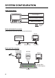
SYSTEM CONFIGURATION Single remote display CAN bus-compliant Device (Power supply) CAN bus-compliant Device DISP BRILL APP TRUE MENU START CLEAR ENT NMEA 0183 Device : Standard : Option RD-33 and NavNet 3D connection Up to three RD-33s can be connected on the CAN bus line.
SYSTEM CONFIGURATION Daisy chain connection FI-50 series Instruments RD-33 RD-33 DISP BRILL APP TRUE MENU START CLEAR ENT DISP BRILL APP TRUE MENU START CLEAR ENT Junction Box FI-5002 12 VDC NMEA 0183, RD-33 and CAN bus device connection FI-50 series Instruments RD-33 NMEA 0183 DISP BRILL 12 VDC APP TRUE MENU START CLEAR ENT NMEA 0183 Device (NavNet VX2 etc.
SYSTEM CONFIGURATION Environmental category RD-33 FI-5002 viii Protected from weather
1. BASIC OPERATION 1.1 Controls 1 DISP 2 BRILL APP TRUE MENU START CLEAR ENT 3 4 5 6 No. 1 Control DISP 7 Main description Short press: Step through the seven data screens in the sequence of Display1 → Display2 → Display3 → Display4 → Display5 → Display6 → Display7 → Display1 → ... Long press: Step through the screens in reverse order. 2 /BRILL Short press: Turn on the power. Adjust the screen brilliance. Long press: Turn off the power.
1. BASIC OPERATION How to remove the hard cover Press here with thumb and pull cover forward. 1.2 How to Turn On/Off the Power Turn on the power Press the key to turn on the power. The start-up screen appears followed by the last-used data screen. RD-33 Booter(1) ver.XX.XX (build:YYYY/MM/DD) Program No: 2651011-XX.XX Initializing... Waiting for update request from SIO... Waiting for update request from CAN... Expanding program... Starting program. RD-33 ver.XX.
1. BASIC OPERATION Turn off the power Press and hold down the key until the screen turns off. The following countdown window appears until the power goes off. Turn Off in 3s. 1.3 How to Adjust the Screen Brilliance/Key Dimmer You can adjust the screen brilliance and key dimmer as follows: 1. Press the key momentarily to show the [Brill] window. 2. For the LCD brilliance, press the key or use the Cursorpad (W or X) to adjust. For the key brilliance, use the Cursorpad (S or T) to adjust. 3.
1. BASIC OPERATION 1.4 How to Step through the Data Screen You can step through the seven data screens with the DISP key. When you press the DISP key momentarily, the screen changes in the sequence of Display1 → Display2 → Display3 → Display4 → Display5 → Display6 → Display7 → Display1 → ... The default screens are as shown below. For details, see sections 2.2 and 2.3. Display1 The screen changes in reverse order with DISP key (long press).
2. PROGRAMMED SCREEN The RD-33 displays the data in three types; digital, analog and graph formats. Also, this equipment provides six programmed screen patterns which meets the purposes; [Fishing], [Sailing], [Ship], [Navigation], [Environment] and [Engine]. Availability of data depends on the sensors connected. 2.1 How to Set the Analog Screen Appearance You can select the analog screen appearance from [A] and [B].
2. PROGRAMMED SCREEN 2. Use the Cursorpad (S or T) to select [Display] and press the ENT key. 3. Use the Cursorpad (S or T) to select [Font Type] and press the ENT key. 4. Use the Cursorpad (S or T) to select [A] or [B] then press the ENT key. 5. Press the DISP key to close the menu and display the data screen. 2.2 How to Set the Programmed Screen The RD-33 provides six programmed screens and each screen has four preset screens. You can select one of them as the data screen. 1.
2. PROGRAMMED SCREEN E.g. [Fishing] screen Note: For [Custom Layout], see the next chapter. 5. Use the Cursorpad to select the screen desired and press the ENT key. 6. Select the screen for [Display2] to [Display7] in the same method. Display options for [Display2] to [Display7] Note: If you selected [Off] on the [Display2] to [Display7], the data screen is skipped by pressing the DISP key. 7. Press the DISP key to close the menu and display the data screen.
2. PROGRAMMED SCREEN Programmed screen patterns Note: For explanation of abbreviations shown on the screen, see APPENDIX 2. Menu item Fishing Description Screen The screen for fishing.
2. PROGRAMMED SCREEN Menu item Sailing Description Screen The screen for sailing.
2. PROGRAMMED SCREEN Menu item Ship Description Screen The screen for ship data.
2. PROGRAMMED SCREEN Menu item Navigation Description Screen The screen for navigation.
2. PROGRAMMED SCREEN Menu item Environment Description Screen The screen for environment.
2. PROGRAMMED SCREEN Menu item Engine Description Screen The screen for engine.
2. PROGRAMMED SCREEN 2.3 How to Customize the Factory-preset Screen You can change the settings of the factory-preset data screen. How to change the display item 1. With the data screen displayed, press the ENT key. The screen changes as below. ENT key E.g. [Fishing] screen pattern 1 2. Use the Cursorpad to select the data box you want to change. The selected data box remains undarkened and the unselected data boxes darken. , , , 3. Press the ENT key.
2. PROGRAMMED SCREEN 4. Use the Cursorpad (S or T) to select the category and press the ENT key. The category options screen, which differs depending on the selected category, appears. Category options (e.g. [Speed] category) Note 1: If you selected [None] in the category list, the data screen is blank. Note 2: For details of each category, see section 3.2. Note 3: The available category and category options depend on the selected screen division.
2. PROGRAMMED SCREEN E.g. SOG properties window 4. Use the Cursorpad (S or T) to select an option and press the ENT key. Options window Setting window Window examples 5. Use the Cursorpad (S or T) to select an option or numeric value then press the ENT key. 6. Repeat steps 4 and 5 to set the other options if necessary. 7. Press the DISP key or the MENU key to close the menu and display the data screen. How to change the custom layout 1. With the data screen displayed, press the ENT key long. 2.
3. CUSTOM SCREEN You can arrange the data to display and show the data in the order desired. Availability of data depends on the sensors connected. 3.1 How to Customize the Screen 1. Press the MENU key to open the menu. 2. Use the Cursorpad (S or T) to select [Display] and press the ENT key. 3. Use the Cursorpad (S or T) to select [Display1 (2, 3, 4, 5, 6 or 7)] and press the ENT key. 4. Use the Cursorpad (S or T) to select [Custom Layout] and press the ENT key.
3. CUSTOM SCREEN 5. Use the Cursorpad to select the screen division and press the ENT key. The option screen depends on the selected screen division. No-spilit Horizontal two-way spilit Four-way spilit Examples of option screen 6. Press the ENT key again with the cursor on [A]. Scroll bar 7. Use the Cursorpad (S or T) to select the category desired and press the ENT key. The scroll bar indicates additional categories. You can scroll through the categories by using the Cursorpad (S or T).
3. CUSTOM SCREEN 8. Use the Cursorpad (S or T) to select an option desired and press the ENT key. Style options (e.g. [Speed] category) Note: The menu items in gray are not available. 9. Use the Cursorpad (S or T) to select [Digital], [Analog] or [Graph] then press the ENT key. If you selected the no-split screen at step 5, go to step 12. For the other types, go to step 10. Note: The available style options depend on the selected screen division, category and category option.
3. CUSTOM SCREEN Category Timer (See section 3.6.) Wind Option Stopwatch Timer1 (2) Wind Speed MAX TWS Wind Angle Low AWA High AWA Beaufort Wind Ground Wind Heading Heading Heading AVG Locked HDG (See section 3.7.) Next Tack COG CMG DMG ROT 3-4 Description Count up timer Count down timer Apparent Wind Speed (AWS): Wind speed measured by wind transducer. True Wind Speed (TWS): Wind speed calculated as if the ship is stationary.
3. CUSTOM SCREEN Category Navigation Option BRG Locked BRG (See section 3.7.) RNG XTE (See section 3.8.) Waypoint No. Waypoint Name Position COG SOG Satellites Roll/Pitch* Roll Pitch Destination ETA Time ETA Date TD Laylines* Description Bearing from your ship to the destination waypoint Use for navigating with bearing for the destination waypoint locked. Analog screen: The pointer indicates variation from the locked bearing. The digital shows the locked bearing or current bearing.
3. CUSTOM SCREEN Category Environment Option Voltage Time (See section 7.5.) Date (See section 7.5.
3. CUSTOM SCREEN 3.3 Data Screen The following are the examples of data screens.
3. CUSTOM SCREEN Four-way split Speed - SOG - Digital Wind - Wind Speed - Digital Heading - Heading - Digital Navigation - Position - Digital Six-way split Speed - Trip - Digital Speed - Odometer - Digital Wind - Wind Angle - Digital Navigation - XTE - Digital Navigation -Roll -Digital Engine - Engine Temp - Digital 3.4 How to Set the Graph Display 3.4.1 How to enable auto range shift The auto range shift feature automatically shifts the display range of a graph to display data on the graph.
3. CUSTOM SCREEN 3. Use the Cursorpad (S or T) to select [Auto Range Shift] and press the ENT key. 4. Use the Cursorpad (T) to select [On] and press the ENT key. To disable the auto range shift, select [Off]. 5. Use the Cursorpad (X) to move the cursor to the right and press the ENT key. 6. Use the Cursorpad (S or T) to set the value and press the ENT key. 7. Press the DISP key to close the menu and display the data screen. 3.4.
3. CUSTOM SCREEN 3.5 How to Switch the Wind Mode and the Direction Mode You can switch the wind mode and the direction mode as follows. Wind mode :Indication To switch the mode, press the APP/TRUE key. [APP]: Apparent or relative wind. The wind direction relative to the ship's bow and the wind speed relative to the moving ship. [True]: True or calculated wind. The wind direction relative to the ship’s bow and the wind speed as if the ship is stationary. [AWS]: Apparent Wind Speed.
3. CUSTOM SCREEN 1. With the data screen displayed, press the ENT key. 2. Press the ENT key long. The properties screen, which depends on the selected data screen, appears. 3. Use the Cursorpad (S or T) to select [Reference] and press the ENT key. 4. Use the Cursorpad (S or T) to select [True] or [Mag] then press the ENT key. [True]: The bearing measured using true North as the reference direction. [Mag]: Magnetic; The bearing measured with magnetic north as the reference direction. 5.
3. CUSTOM SCREEN Stopwatch To start the timer, press the START/CLEAR key. To lap or stop the timer, press the START/CLEAR key. Though the time indication stops, the count is continued internally. To start the timer again, press the START/CLEAR key again. START/CLEAR key [Stopwatch]: Count up timer Timer1 (2) Set the time with the Cursorpad (T) (default is 15:00.0 (maximum)). To start the timer, press the START/CLEAR key. To lap or stop the timer, press the START/CLEAR key.
3. CUSTOM SCREEN 3.7 Locked HDG/BRG Analog screen Lock the heading or bearing at desired angle and display the variation from the locked heading or bearing in the analog meter. This function is available for no-split screen and horizontal/vertical three-way split 3 ( ) screen. To display the locked heading or locked bearing screen, select [Locked HDG] or [Locked BRG] on the [Heading] or [Navigation] category (see sections 3.1 and 3.2). Press the START/CLEAR key to lock the heading or bearing.
3. CUSTOM SCREEN 3. Use the Cursorpad (S or T) to select [Style] and use the Cursorpad (X) to move the cursor to the right. 4. Press the ENT key. E.g. [Locked HDG] 5. Use the Cursorpad (S or T) to select [Current Heading] or [Current Bearing] then press the ENT key. 6. Press the DISP key to close the menu and display the data screen. Note 1: See section 3.5 for instructions on changing the direction mode. Note 2: You can perform this operation in the [System] menu (see section 7.6).
3. CUSTOM SCREEN 3.8 Cross-Track Error The cross-track error is displayed in the highway screen in analog format. The highway screen provides a graphic presentation of ship’s progress toward a destination waypoint, with range and bearing to the destination waypoint, ship’s course and speed, and the ship’s position. Select [XTE] on the [Navigation] category (see sections 3.1 and 3.2).
3. CUSTOM SCREEN How to change the unit You can select the XTE unit from nm, km or sm as follows: 1. With the data screen for XTE displayed, press the ENT key. 2. Press the ENT key long. 3. Use the Cursorpad (S or T) to select [Unit] and press the ENT key. 4. Use the Cursorpad (S or T) to select [nm], [km] or [sm] then press the ENT key. 5. Press the DISP key to close the menu and display the data screen. How to change the scale range You can change the scale range for analog XTE.
3. CUSTOM SCREEN 3.9 How to Switch the Digital Data for Heading and Wind Angle You can switch the digital data on the analog screen as follows. , Heading (Available for , , ) Use the Cursorpad (X) to switch the digital data for heading. The digital data changes as follows. The data changes in reverse order with the Cursorpad (W). E.g. Magnetic heading Wind Angle (Available for ) Use the Cursorpad (X) to switch the digital data for wind angle. The digital data changes as follows.
3. CUSTOM SCREEN 3.10 How to Reset the Value You can reset the value for the following options by pressing the START/CLEAR key long. Category Speed Timer Wind Heading Option STW MAX, STW AVG, SOG MAX, SOG AVG, Trip*1 Stopwatch, Timer1, Timer2 MAX TWS, Low AWA, High AWA Heading AVG, CMG*2, DMG*2 *1: When [Trip . ODO] in the [System] menu is set to [External], trip for the sensor is reset. The sensor must output PGN 126208 (Acknowledge Group Function) in order to reset trip.
4. ALARMS 4.1 Overview The RD-33 has 17 types of alarms as follows: • • • • • • Arrival/Anchor STW Depth Time Out Odometer Low Battery High APP Wind Angle • • • • • • XTE Water Temperature Time Roll Max True Wind Speed Low APP Wind Angle • • • • • SOG Depth Trip Pitch Low True Wind Speed When the alarm activates, the audio alarm sounds and the alarm message appears. The alarm icon flashes at the upper-right corner of the screen.
4. ALARMS 2. Use the Cursorpad (S or T) to select [Messages] and press the ENT key. All alarms currently violated are displayed. 3. Press the DISP key to close the menu and display the data screen.
4. ALARMS Alarm category TIME ALARM! TRIP ALARM! ODOMETER ALARM! ROLL ALARM! PITCH ALARM! BATTERY ALARM! MAX TRUE WIND SPEED ALARM! LOW TRUE WIND SPEED ALARM! HIGH APPARENT WIND ANGLE ALARM! LOW APPARENT WIND ANGLE ALARM! RAM ERROR! ROM ERROR! Meaning The preset time arrives. Your ship has traveled the trip distance setting or above. Your ship has traveled the odometer distance setting or above. The right and left sway of your ship is equal to or exceeds the roll setting.
4. ALARMS 4.2 Audio Alarm Type You can select the audio alarm type as follows: 1. Open the [Alarms] menu. 2. Use the Cursorpad (S or T) to select [Buzzer] and press the ENT key. 3. Use the Cursorpad (S or T) to select [Short], [Long] or [Continuous] then press the ENT key. [Short]: One short beep [Long]: Three long beeps [Continuous]: Continuous long beeps until you press any key to acknowledge the alarm 4. Press the DISP key to close the menu and display the data screen. 4.3 How to Set the Alarms 4.
4. ALARMS 4. Use the Cursorpad (X) to move the cursor to the right and press the ENT key. 5. Use the Cursorpad to set the value and press the ENT key. The circle with radius setting value is alarm zone. S, T: Change the figure. W, X: Move the cursor for digit. 6. Press the DISP key to close the menu and display the data screen. Note: The anchor alarm cannot be activated when there is no position data. If the position data is lost when the anchor alarm is on, an alarm occurs. 4.3.
4. ALARMS 2. Use the Cursorpad (S or T) to select [SOG] or [STW] then press the ENT key. 3. Use the Cursorpad (S or T) to select [Low], [High], [Within] or [Outside] then press the ENT key. When you do not set the SOG/STW alarm, select [Off] and go to step 6. [Low]: Alarm occurs when your ship’s speed is equal to or lower than the speed setting. [High]: Alarm occurs when your ship’s speed is equal to or higher than the speed setting.
4. ALARMS 2. Use the Cursorpad (S or T) to select [Water Temperature] and press the ENT key. 3. Use the Cursorpad (S or T) to select [Low], [High], [Within], [Outside] or [Shear] then press the ENT key. When you do not set the water temperature alarm, select [Off] and go to step 6. [Low]: Alarm occurs when the water temperature is equal to or lower than the temperature setting. [High]: Alarm occurs when the water temperature is equal to or higher than the temperature setting.
4. ALARMS 4.3.5 Depth alarm The depth alarm alerts you when the depth is lower or higher than the depth setting, is inside or outside of the depth range setting, or is equal to the depth setting. 1. Open the [Alarms] menu. 2. Use the Cursorpad (S or T) to select [Depth] and press the ENT key. 3. Use the Cursorpad (S or T) to select [Low], [High], [Within] or [Outside] then press the ENT key. When you do not set the depth alarm, select [Off] and go to step 6.
4. ALARMS 2. Use the Cursorpad (S or T) to select [Depth Time Out] and press the ENT key. 3. Use the Cursorpad (S or T) to select [On] and press the ENT key. When you do not set the depth time out alarm, select [Off] and go to step 6. 4. Use the Cursorpad (X) to move the cursor to the right and press the ENT key. 5. Use the Cursorpad (S or T) to select the time and press the ENT key. 6. Press the DISP key to close the menu and display the data screen. 4.3.
4. ALARMS 3. Use the Cursorpad (S or T) to select [On] and press the ENT key. When you do not set the roll/pitch alarm, select [Off] and go to step 6. 4. Use the Cursorpad (X) to move the cursor to the right and press the ENT key. 5. Use the Cursorpad (S or T) to set the value and press the ENT key. 6. Press the DISP key to close the menu and display the data screen. 4.3.9 Other alarms The following are the other alarms. Menu item 4-10 Description Remarks Time data required.
5. INPUT/OUTPUT SETUP The RD-33 inputs and outputs the signal in NMEA 0183 and CAN bus format. CAN bus is the network system based on NMEA 2000. 5.1 Received Data Status You can display all data input from the sensor. See the following table about the data. Depth Depth Speed STW, SOG, Trip, Odometer Wind APP Wind Speed, True Wind Speed, APP Wind Angle, True Wind Angle Heading Heading, Variation, Deviation, COG, ROT Navigation BRG, RNG, XTE, Waypoint No.
5. INPUT/OUTPUT SETUP 5.2 CAN bus Devices Status You can display the status for up to 30 CAN bus devices connected. You can nickname each device and these nicknames are used on the [Data Source] screen (see section 5.3). Note: The status for NMEA0183 devices is not displayed. 1. Press the MENU key to open the menu. 2. Use the Cursorpad (S or T) to select [I/O Setup] and press the ENT key. 3. Use the Cursorpad (S or T) to select [CAN bus Devices] and press the ENT key.
5. INPUT/OUTPUT SETUP 5.3 Data Source Set the data source and output the input data, in PGN format. How to select the data source You can select the data source to display on the screen when data of the same type is input from multiple sources. For example, you can select the position data from GPS navigation equipment or the position data from satellite compass when these two position data are input.
5. INPUT/OUTPUT SETUP 5. Use the Cursorpad (S or T) to select [On] and press the ENT key. 6. Press the DISP key to close the menu and display the data screen. Note: PGN transmission by the RD-33 is turned off when an external device connected to the CAN bus network also has PGN transmission turned off. 5.4 NMEA0183 Output Mode The [Mix] feature in the [NMEA0183 Output Mode] outputs inputted NMEA0183 format data to external equipment, in NMEA0183 format. The [NMEA2000 TRANS.
6. POSITION/TD SETUP, LAYLINES You can display the position of your ship in latitude and longitude or Loran C TDs. Also, you can display the laylines which is the indication of navigation at yacht sailing. 6.1 Display Format for the Position of Your Ship Set the display format for the position of your ship. 1. Press the MENU key to open the menu. 2. Use the Cursorpad (S or T) to select [Pos/TD Setup] and press the ENT key. 3. Use the Cursorpad (S or T) to select [Display] and press the ENT key. 4.
6. POSITION/TD SETUP, LAYLINES 5. If you selected [LC TD], do the following steps. 1) Use the Cursorpad (S or T) to select [Loran C] and press the ENT key. Slave station pair GRI code 2) Use the Cursorpad (S or T) to select the GRI (Group Repetition Interval) code desired and press the ENT key. 3) Use the Cursorpad (X) to move the cursor to the slave station pair field then press the ENT key. 4) Use the Cursorpad (S or T) to select a slave station pair then press the ENT key.
6. POSITION/TD SETUP, LAYLINES 1. Press the MENU key to open the menu. 2. Use the Cursorpad (S or T) to select [Laylines] and press the ENT key. 3. Use the Cursorpad (S or T) to select [Upwind Angle Display] and press the ENT key. Setting window for upwind 4. Use the Cursorpad (S or T) to set the angle and press the ENT key. WP0001 45° 45° a° Ground wind a° = Ground wind - BRG 5. Repeat steps 3 and 4 to set the angle for [Downwind Angle Display]. 6.
6. POSITION/TD SETUP, LAYLINES 8. Use the Cursorpad (X) to move the cursor to the right and press the ENT key. 9. Use the Cursorpad (S or T) to set the time interval and press the ENT key. You can display the five past laylines per setting time interval. 10. Press the DISP key to close the menu and display the data screen. The past laylines are displayed in light blue.
7. SYSTEM MENU This chapter describes the [System] menu. For [Demo Mode], [Self Test] and [Factory Reset], see chapter 8. 7.1 Units of Measurement You can set the units of measurement for depth, ship speed, distance, wind speed, water temperature, fuel and engine pressure. 1. Press the MENU key to open the menu. 2. Use the Cursorpad (S or T) to select [System] and press the ENT key. 3. Use the Cursorpad (S or T) to select [Units] and press the ENT key.
7. SYSTEM MENU 4. Use the Cursorpad (S or T) to select [Depth], [Speed], [Distance], [Wind Speed], [Temperature], [Fuel] or [Engine Pressure] then press the ENT key. Depth Speed Temperature Fuel Distance Wind Speed Engine Pressure 5. Use the Cursorpad (S or T) to select an option and press the ENT key. 6. Press the DISP key to close the menu and display the data screen. 7.
7. SYSTEM MENU 6. Use the Cursorpad (S or T) to set the value and use the Cursorpad (X) to move the cursor to the next digit. Repeat this step to set the value for other digits if necessary. When the displayed data is smaller than the actual value, set the plus value. When the displayed data is larger than the actual value, set the minus value. 7. Press the ENT key to save the setting and close the setting window. To close the window without saving, press the MENU key (instead of the ENT key). 8.
7. SYSTEM MENU 7.3 Response Time You can set the response time for each data as follows. The input raw data is averaged by the response time. 1. Press the MENU key to open the menu. 2. Use the Cursorpad (S or T) to select [System] and press the ENT key. 3. Use the Cursorpad (S or T) to select [Response Time] and press the ENT key. 4. Use the Cursorpad (S or T) to select the menu item desired and press the ENT key. 5. Use the Cursorpad (S or T) to set the value and press the ENT key to save the setting.
7. SYSTEM MENU 3. Use the Cursorpad (S or T) to select [Scale Ranges] and press the ENT key. 4. Use the Cursorpad (S or T) to select the menu item desired and press the ENT key. 5. Use the Cursorpad (S or T) to select an option and press the ENT key.
7. SYSTEM MENU 3. Use the Cursorpad (S or T) to select [Time Display] or [Date Display] then press the ENT key. Time Display Date Display 4. Use the Cursorpad (S or T) to select an option and press the ENT key. 5. Press the DISP key to close the menu and display the data screen.
7. SYSTEM MENU 7.6 Other Menu Items This section describes the menu items not previously described. [Key Beep]: When a key is pressed, a beep sounds. You can turn on or off this beep. [Language]: English and other languages are available. [HDG/COG Ref]: You can display the bearing in true or magnetic. [True] is the bearing measured using true North as the reference direction. "T" is displayed on the screen. [Mag] is the bearing measured with magnetic north as the reference direction.
7. SYSTEM MENU This page is intentionally left blank.
8. MAINTENANCE, TROUBLESHOOTING NOTICE Do not apply paint, anti-corrosive sealant or contact spray to plastic parts or equipment coating. Those items contain products that can damage plastic parts and equipment coating. 8.1 Maintenance Check the following points regularly to maintain performance: • Check that connections on the rear panel are firmly tightened and free of dust. • Check that the grounding point is free of rust and the ground wire is tightly fastened.
8. MAINTENANCE, TROUBLESHOOTING 8.2 Troubleshooting This section provides simple troubleshooting procedures which the user can follow to restore normal operation. If you cannot restore normal operation, do not check inside the unit. Have a qualified technician check the equipment. Symptom Remedy You cannot turn on the power. No picture appears. 8.3 • Check that the power cable is firmly fastened. • Check for damaged power cable and connector. Press the brilliance.
8. MAINTENANCE, TROUBLESHOOTING System Test items No. Items Description 1 ROM, RAM The results of the ROM/RAM test are displayed as "OK" or "NG" (No Good). If any NG is displayed, contact your dealer. 2 0183 The result of the port NMEA 0183 is displayed as "OK" or "--". Port NMEA 0183 requires a special connector to test it. When a special connector is not connected, "--" is shown. 3 Program version (CPU Main, CPU Boot, CPU CAN LD) Each program number and program version number are displayed.
8. MAINTENANCE, TROUBLESHOOTING 8.4 Factory Reset You can restore all settings as follows: 1. Press the MENU key to open the menu. 2. Use the Cursorpad (S or T) to select [System] and press the ENT key. 3. Use the Cursorpad (S or T) to select [Factory Reset] and press the ENT key. 4. Use the Cursorpad (S or T) to select [On] and press the ENT key. The confirmation message appears. 5. Use the Cursorpad (W) to select [Yes] and press the ENT key. The equipment restarts with the default settings.
9. INSTALLATION 9.1 Equipment List Standard supply Name Remote Display Installation Materials Accessories Type RD-33 CP20-03300 Code No. - FP20-01200* 001-087-250 Qty 1 1 1 Remarks • CP20-03310* • M12-05BM+05BF-060 *: See page A-1. Optional supply Name Junction Box Cable Assy. FI-5002 FI-50-CHAIN-0.3M Code No. 000-166-949-11 Cable Assy.
9. INSTALLATION 9.2 Installation Mounting considerations The remote display can be installed on a desktop, on the underside of a table, or flush mounted in a panel. When you select a mounting location, remember the following points: • The nominal viewing distance for the display unit is 0.6 m. Select a suitable mounting location considering that distance. • Locate the remote display away from exhaust pipes and vents. • Select an installation location that is well ventilated.
9. INSTALLATION 5. Attach the F mount cushion (supplied as accessories) to the remote display from the rear side. 6. Connect the cable connectors (see section 9.3). 7. Set the remote display to the cutout and fasten it with four self-tapping screws (supplied as installation material; 3x20). 8. Set the front panel to the remote display.
9. INSTALLATION 6. Tighten the knobs to fasten the hanger to the remote display. DISP BRILL 9.3 APP TRUE MENU START CLEAR ENT Wiring Refer to the following illustration and the interconnection diagram (page S-1) to connect cables. Note: The remote display power is supplied through CAN bus. When the sensor signal is input or output only from the NMEA 0183 device without the CAN bus device, connect the 12-24 VDC power from the ship’s switch board to the male connector of the CAN bus port.
9. INSTALLATION Connection between remote display and junction box For serviceman: See “Furuno CAN bus Network Design Guide” (TIE-00170-X) for details about CAN bus network. RD-33 (rear) M12-05BM+05BF-0xx (1 m, 2 m, 6 m) Connect to CN2 - CN5. FI-5002 Power cable (2 m) White + Black – 12 VDC Power switchboard 12 VDC Side view CN2 CN3 - CN5 BACKBONE DROP MC connector Top view Fix cable with supplied cable ties.
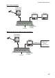
9. INSTALLATION Terminator • Connection to the backbone cable RD-33 NavNet 3D (Power supply) DISP BRILL APP TRUE MENU START CLEAR ENT Terminator Terminator Furuno CAN bus terminators are available with the following part numbers. The terminator should be attached at each end of the backbone cable.
9. INSTALLATION 9.4 Adjustments After you install the remote display, initialize the remote display as follows: 1. Press the key to turn on the power. 2. Press the ENT key with the cursor on [English]. The menu for units of measurement appears. 3. Use the Cursorpad (S or T) to select the menu item desired and press the ENT key. Depth Temperature Speed Fuel Distance Engine Pressure Wind Speed Time Offset* *: Set the difference between UTC (Universal time coordinated) and local time. 4.
9. INSTALLATION 9.5 Input/Output Signal The RD-33 inputs and outputs the signal in NMEA 0183 and CAN bus format.
9.
9. INSTALLATION Data Humidity Rudder Engine Current (tide) Port Sentence, PGN (Title) CAN bus 130311 (Environmental Parameters) NMEA 0183 MDA CAN bus 127245 (Rudder) NMEA 0183 RSA CAN bus 127497 (Trip Parameters, Engine), 127488 (Engine Parameters, Rapid Update), 127489 (Engine Parameters, Dynamic) NMEA 0183 - CAN bus - NMEA 0183 CUR > VDR Note 1: >: The priority of the left sentence is higher than the one of right sentence.
9.
9.
APPENDIX 1 MENU TREE MENU key Display Bold: Default setting Display1 (Fishing, Sailing, Ship, Navigation, Environment, Engine, Custom Layout) Display2 (Fishing, Sailing, Ship, Navigation, Environment, Engine, Custom Layout, Off) Display3 (Fishing, Sailing, Ship, Navigation, Environment, Engine, Custom Layout, Off) Display4 (Fishing, Sailing, Ship, Navigation, Environment, Engine, Custom Layout, Off) Display5 (Fishing, Sailing, Ship, Navigation, Environment, Engine, Custom Layout, Off) Display6 (Fishing, Sa
APPENDIX 1 MENU TREE (Continued from previous page) Pos/TD Setup Display (xx.xxx’ , xx’ xx.x’’ , LC TD) Loran C (List of Loran-C chains and pairs of slave stations) TD1 (Offset: -99.9 - +99.9; +0.0) TD2 (Offset: -99.9 - +99.9; +0.
APPENDIX 1 MENU TREE (Continued from previous page) Scale Speed (0-20kn, 0-40kn, 0-80kn) Ranges Volts (8-16V, 16-32V) Engine Speed RPM (0-40x100RPM, 0-60x100RPM, 0-80x100RPM) Engine Boost Pressure (0-30psi, 0-70psi, 0-150psi, 0-360psi, 0-440psi) Engine Temperature (150-250°F, 120-300°F) Engine Oil Pressure (0-30psi, 0-70psi, 0-150psi, 0-360psi, 0-440psi) Engine Oil Temperature (150-250°F, 120-300°F) Engine Coolant Pressure (0-30psi, 0-70psi, 0-150psi, 0-360psi, 0-440psi) HDG/COG Ref (True, Mag) Magneti
APPENDIX 2 LIST OF TERMS The following table shows the terms used in the RD-33. Term Meaning A(ir) Press Air Pressure Air Temp Air Temperature APP Apparent: Aapparent or relative wind. The wind direction relative to the ship’s bow and the wind speed relative to the moving vessel.
APPENDIX 2 LIST OF TERMS Term Meaning Oil P Oil Pressure P Port POSN Position psi Pound per square inch RNG Range ROT Rate Of Turn RPM Revolutions Per Minute S Starboard s second(s) SAT Satellite SOG Speed Over the Ground SPD Speed STW Speed Through the Water STWAVG Speed Through the Water Average STWMAX Speed Through the Water Maximum T True: True wind. The wind direction relative to the ship’s bow and the wind speed as if the ship is stationary. T True: True bearing.
APPENDIX 2 LIST OF TERMS This page is intentionally left blank.
FURUNO RD-33 SPECIFICATIONS OF REMOTE DISPLAY RD-33 1 GENERAL 1.1 Display type 4.3-inch color LCD, 480 x 272 dots (WQVGA) 1.2 Picture color 256 colors 1.3 Display mode Digital, Analog, Graph 1.4 Data indication Ship’s speed, Course, Heading, Trip, Depth, Wind direction/speed, Navigate information, Environmental information, Rudder angle, Engine’s information 1.
A-1 C4458-M01-B C4458-F01-C
D-1
D-2
C B A クロ BLK NOTE *1: SHIPYARD SUPPLY. *2: OPTION. *3: WHEN CAN bus NETWORK IS NOT USED. *4: CONNECT WIRES AFTER CONNECTOR PLUG REOVED. *3 (+) (-) 選択 SELECT 同上 DITTO 同上 DITTO CN5 DROP_L SHIELD 1 NET-S 2 NET-C 3 NET-H 4 NET-L 5 DWG.No.
This page is intentionally left blank .
INDEX A Adjustments .............................................. 9-7 Alarm category .......................................... 4-2 Alarm menu............................................... 4-3 Alarm status .............................................. 4-1 Analog screen appearance ....................... 2-1 Anchor alarm............................................. 4-4 Arrival alarm .............................................. 4-4 Audio alarm ........................................
INDEX X XTE (Cross track error) ............................3-15 XTE alarm ..................................................
FURUNO Worldwide Warranty for Pleasure Boats (Except North America) This warranty is valid for products manufactured by Furuno Electric Co. (hereafter FURUNO) and installed on a pleasure boat. Any web based purchases that are imported into other countries by anyone other than a FURUNO certified dealer may not comply with local standards.
FURUNO Warranty for North America FURUNO U.S.A., Limited Warranty provides a twenty-four (24) months LABOR and twenty-four (24) months PARTS warranty on products from the date of installation or purchase by the original owner. Products or components that are represented as being waterproof are guaranteed to be waterproof only for, and within the limits, of the warranty period stated above.