
Operator's Manual

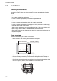
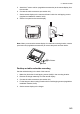

9. INSTALLATION
9-6
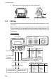
Terminator
• Connection to the backbone cable
Furuno CAN bus terminators are available with the following part numbers. The ter-
minator should be attached at each end of the backbone cable.
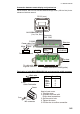
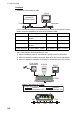
• Connection to the Junction box FI-5002
The FI-5002 has two terminal resistors (R1, R2).
1) When no backbone cable is connected, R1 and R2 are set to ON position.
2) When one backbone cable is connected, either R1 or R2 is set to ON position.
3) When two backbone cables are connected, R1 and R2 are set to OFF position.
Parts name Type Code Number Remarks
Male terminator LTWMN-05AMMT-
SL8001
000-160-508-10 Mini connector
Female terminator LTWMN-05AFFT-SL8001 000-160-509-10 Mini connector
Male terminator LTWMC-05BMMT-
SL8001
000-168-604-10 Micro connector
Female terminator LTWMC-05BFFT-SL8001 000-168-605-10 Micro connector
NavNet 3D
(Power supply)
RD-33
DISP
APP
TRUE
MENU
START
CLEAR
ENT
B
R
I
L
L
Terminator
Terminator
12 VDC
FI-50 series
Instruments
CN1
CN1
CN3
CN3
CN4
CN4
CN5
CN5
CN2
CN2
R2
R1
CN2-CN5
FI-5002
Internal Terminators in FI-5002
CN3 CN4 CN5
CN2
CN2
: Resistor is
disconnected. (OFF)
: Resistor is
connected. (ON)
Jumper block setting
WS-200
RD-33
DISP
APP
TRUE
MENU
START
CLEAR
ENT
B
R
I
L
L