OPERATOR'S MANUAL THD SATELLITE COMPASS MODEL SC-110 www.furuno.co.
The paper used in this manual is elemental chlorine free. ・FURUNO Authorized Distributor/Dealer 9-52 Ashihara-cho, Nishinomiya, 662-8580, JAPAN Telephone : +81-(0)798-65-2111 Fax : +81-(0)798-65-4200 All rights reserved. Printed in Japan A : FEB . 2004 F : FEB . 08, 2011 Pub. No.
IMPORTANT NOTICES General • The operator of this equipment must read and follow the descriptions in this manual. Wrong operation or maintenance can cancel the warranty or cause injury. • Do not copy any part of this manual without written permission from FURUNO. • If this manual is lost or worn, contact your dealer about replacement. • The contents of this manual and equipment specifications can change without notice.
SAFETY INSTRUCTIONS The operator and installer must read the applicable safety instructions before attempting to install or operate the equipment. WARNING Indicates a potentially hazardous situation which, if not avoided, could result in death or serious injury. CAUTION Indicates a potentially hazardous situation which, if not avoided, can result in minor or moderate injury.
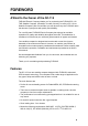
TABLE OF CONTENTS FOREWORD.................................................................................................................... v SYSTEM CONFIGURATION .......................................................................................... vi EQUIPMENT LIST ......................................................................................................... vii SPECIFICATIONS .....................................................................................................
2.10 2.11 2.12 2.13 2.14 2.9.4 Time format............................................................................................................2-15 2.9.5 Demonstration mode .............................................................................................2-16 WAAS/DGPS Setup ..........................................................................................................2-17 OTHERS Menu ..............................................................................................
FOREWORD A Word to the Owner of the SC-110 FURUNO Electric Company thanks you for purchasing the FURUNO SC-110 THD Satellite Compass. (Hereafter, for sake of brevity, we refer to SC-110 as Satellite Compass.) We are confident you will discover why the FURUNO name has become synonymous with quality and reliability. For over 60 years FURUNO Electric Company has enjoyed an enviable reputation for quality and reliability throughout the world.
SYSTEM CONFIGURATION The SC-110 consists of an antenna, a display unit and a processor unit. The tri-antenna system helps reduce the influence of ship's motion (rolling).
EQUIPMENT LIST Standard supply Name GPS Antenna Display Unit Processor Unit Installation Materials Spare Parts Type SC-1203F SC-502 SC-1101 CP20-02230* CP20-02260* CP20-02241* Code No. 004-378-110 004-379-660 004-378-200 Qty 1 1 1 CP20-02600 000-041-905 1 CP20-02203* 004-380-660 1 SP20-01101* 004-379-720 1 Remarks Radome type TPPX cable TNC cable For antenna unit For processor unit: CP20-02601*, MJ-A7SPF0006-100 For display unit: Tapping screw (5X20, 4 pcs.
This page intentionally left blank.
FURUNO SC-110 SPECIFICATIONS OF SATELLITE COMPASS SC-110 1 1.1 1.2 1.3 1.4 1.5 1.6 GENERAL Heading accuracy 0.3° RMS (95% static accuracy) Heading resolution 0.
FURUNO 5 5.1 5.2 5.3 COATING COLOR Display unit Processor unit Antenna unit SC-110 Panel: N3.0, Chassis: 2.5GY5/1.5 2.5GY5/1.5 N9.
1 INSTALLATION 1.1 Mounting Considerations 1.1.1 Antenna unit General • Keep the length of the antenna cable in mind when selecting a mounting location. Installing the antenna above superstructures • The antenna must be mounted above all other structures on the vessel to obtain an unobstructed view of the satellites regardless of vessel heading. Failure to do so will cause shadows and multipath reflection problems.
1. INSTALLATION • The horizontal separation between the antenna and masts must be as follows: Mast diameter 10 cm 30 cm Separation distance (minimum) 1.5 m 3m -80° +80° SC-series Antenna Less than 10° Mast, etc. Separation degrees • Keep the length of antenna cable in mind when selecting a mounting location. The cable comes in lengths of 15 meters (standard supply), or 30 m or 50 m (optional lengths). • The field of view above the antenna should be as shown below, ±80° against zenith.
1. INSTALLATION Location influenced by reflected wave. Radar Antenna SC-series Antenna Reception blocked by mast. Bridge Example of antenna installed below superstructures 1.1.2 Display unit, processor unit • Choose a location where vibration and shock are minimal. • Install the units well away from locations subject to rain and water splash. • Locate the units away from air conditioner vents. • Keep the units out of direct sunlight because of heat that can build up inside their cabinets.
1. INSTALLATION 1.2 Installing the Antenna Unit Note: “Bird-repellent fixtures” may be attached to each antenna element and the center cover to prevent birds from alighting on them. If it is more convenient to attach them before fixing the antenna unit to the mounting location, do step 7 before fixing the antenna unit. 1. Prepare a post for the antenna as shown in the illustration below. Recommended Flange (Option) Name: Flange Type: OP20-31 Code No.
1. INSTALLATION 2. Fix the antenna unit to the post as shown below. 3 1 2 Fix the #1 and #2 antennas on the fore-and-aft line of the ship, with the #2 antenna forward of the #1 antenna. Set the antenna unit to the flange. Flat washer Spring washer Nut (Torque: 29.
1. INSTALLATION 3. Coat each nut, bolt and washer with silicone rubber for waterproofing. Coat bolt, nut and washer completely with silicone rubber. Coating bolt, nut and washer with silicone rubber 4. As shown below, make a loop in the antenna cable and fasten the antenna cable to the antenna post with two cable ties. Coat bolt threads with Three Bond. Fasten bolt with nuts and then coat nuts with Three Bond also. Coat with Three Bond 1211 (supplied). Fix antenna cable. 5.
1. INSTALLATION 1.3 Installing the Processor Unit The processor unit should be mounted aligned with the ship’s fore-and-aft line. It can be mounted on the deck, bulkhead, or on the underside of a desk. Choose a mounting location which allows you to easily view the power lamp on the top of the unit and which is within ±2.5° of the ship’s fore-and-aft line. 1.3.1 Bulkhead mount The processor unit is shipped from the factory ready for bulkhead mounting.
1. INSTALLATION 1.3.2 Deck mount Orient the processor unit as shown below and fix it to the mounting location with four tapping screws (M5x20). You will set the orientation later on the menu. Mount processor unit so reference direction is within ±2.5° of fore-and-aft line.
1. INSTALLATION 1.3.3 Installation on the underside of a desk The processor unit may be mounted on the underside of a desk as shown in the figure below. Do not install it on the overhead. Desk Name Plate Installation of processor unit on the underside of a desk Reference Direction Mount processor unit so reference direction is within ±2.5° of fore-and-aft line.
1. INSTALLATION 1.4 Installing the Display Unit The display unit can be installed on a desktop, overhead, or flush mounted in a console. The optimal viewing distance is 0.5 m. 1.4.1 Desktop, overhead mounting 1. Fasten the hanger to the mounting location with four tapping screws (supplied). See the outline drawing for mounting dimensions. 2. Screw the knobs into the display unit. 3. Set display unit to the hanger and tighten the knobs. 4.
1. INSTALLATION Flush mount “S” Flush mount “S” kit Name Flush Mount Fixture Wing Bolt Wing Nut Hex Bolt Spring Washer Type: OP20-17, Code No.: 000-040-720) Type 20-007-2401 M4X30 M4 M6X12 M6 Code No. 100-183-190 000-804-799 000-863-306 000-862-127 000-864-260 Qty 2 4 4 2 2 1. Make a cutout in the mounting location. The dimensions are 167(W) x 92(H) mm. 2. Place the display unit in the cutout. 3. Fix the display unit to the two flush mount fixtures with hex bolts and spring washers. 4.
1. INSTALLATION 1.5 Wiring This section covers general wiring. For further details see the interconnection diagram at the back of this manual. ANTENNA UNIT SC-1203F PROCESSOR UNIT SC-1101 DPYC 1.5 TPPX6-3D2V-15M, 15m or TNC-PS-3D-15 (3 pcs.) 12-24 VDC MJ-A7SPF0006-100, 10m DISPLAY UNIT SC-502 * GPS ANT 1 2 3 DISPLAY ANTENNA Terminals GPS ANT1: No color GPS ANT2: Yellow line GPS ANT3: Red line (using cable TPPX6-3D2V-15M) Cable from display Wiring 1-12 Ground Terminal Connect IV-2.
1. INSTALLATION Note 1: Use cable type DPYC-1.5 (or equivalent) for the power cable. DPYC-1.5 Armor Sheath φ = 11.7 mm Conductor S = 1.5 mm 2 φ = 1.56 mm Sectional view of coaxial cable DPYC-1.5 Note 2: The optional antenna cable set (CP20-01700 or CP20-01710) allows you to extend antenna cable length to 30 m (50 m). See next page for how to attach the connector. Wrap each junction with tape. Attach connector N-P-8DFB in field; wrap each junction with tape.
1. INSTALLATION How to attach connector N-P-8DFB Outer Sheath Armor Inner Sheath Shield (Dimensions in millimeters.) 30 50 Cover with heat-shrink tubing and heat. Cut off insulator and core by 10 mm. 10 Twist shield end. Slip on clamp nut, gasket and clamp as shown left. Clamp Nut Gasket Clamp (reddish brown) Aluminum Foil Fold back shield over clamp and trim. Trim shield here. Insulator Cut aluminum foil at four places, 90 from one another. Fold back aluminum foil onto shield and trim.
1. INSTALLATION 1.6 Initial Settings Follow the procedures in this section to enter initial settings. NOTICE Improper menu settings may stop output of data and display the message "RATE ERROR." Be sure to enter correct data. 1.6.1 Confirming satellite status Press the [SAT STATUS] key. Satellites used for measurement SAT TRACKING STATUS Satellites being tracked TIMER 5 '52" OK NO.
1. INSTALLATION 1.6.2 Choosing mounting method 1. Turn on the processor unit and then press the [MENU] key to show the menu. MAIN MENU ALARMS MESSAGES GPS SETUP SYS SETUP SOFT VER. OTHERS SATELLITE WAAS/DGPS I/O SETUP INST MENU ERASE TRIP MENU Main menu 2. Use the Omnipad ( key. ) to choose “INST MENU” and then press the [ENT] INSTALLATION SETUP MOUNTING DIRECTION : WALL :A LANGUAGE : ENG ROLL OFFSET : 0.0 PITCH OFFSET : 0.0 Installation setup menu 3. “MOUNTING” is selected; press the [ENT] key. 4.
1. INSTALLATION 1.7 Connection of External Equipment 1.7.1 General wiring All external equipment are terminated on the MAIN Board inside the processor unit. Turn off the power and unfasten four screws to remove the cover. Connect wiring from external equipment referring to the interconnection diagram. Use the opener supplied to open terminal blocks, referring to the instructions below. Recommended Cables*: Power cable: DPYC-1.
1. INSTALLATION 1.7.2 Fabrication of cables Cable Power cable DPCY-1.5 (or equivalent) Sectional view, fabrication 50 Armor Sheath Armor Sheath φ = 11.7 mm Cut the sheath. Conductor S = 1.5 mm 2 φ = 1.56 mm 15 6 SECTIONAL VIEW Cable for IEC 61162 format equipment (JIS cable TTYCS-1 or equivalent) 50 Vinyl tape Crimp-on lug FV1.25-5 FABRICATION 3 80 Armor Braided shield Armor Sheath Shield φ = 10.1 mm Conductor S = 0.75 mm 2 φ = 1.11 mm 8 Twist and cut.
2 OPERATION 2.1 Controls MENU key: Opens menu. DISP key: Selects display; closes menu. Omnipad: Selects menu items; shifts cursor. MENU ENT ENT key: Terminates key input. DISP DIM DIM key: Adjusts panel illumination, display contrast. HDG SETUP SATELLITE SAT COMPASS STATUS HDG SETUP key: Chooses heading source. SAT STATUS key: Shows satellite tracking status. See the illustration on page 1-15. HOW TO REMOVE THE COVER Press here and pull toward you to remove cover.
2. OPERATION 2.2 Turning the Power On/Off Use the power switch on the processor unit to turn the power to the display unit on and off. POWER Switch Processor unit A beep sounds and the display starts up with the last-used display. Note: If backup heading data is used the heading indication flashes until faithful heading data becomes available. 2.3 Panel Illumination, Display Contrast Adjust panel illumination and display contrast as shown below. The default values are 4 and 45, respectively. 1.
2. OPERATION 2.4 Choosing a Display Use the [DISP] key to show a display desired. 2.4.1 Description of displays Heading display The heading display shows heading, course, speed, date, time and position-fixing status. The heading status mark changes in the sequence shown below. The “final calculations” mark disappears after heading becomes reliable, which is approximately 90 seconds after that mark appears.
2. OPERATION Steering display The steering display shows heading in digital and analog form. SOG and COG are also indicated. Note that COG accuracy is low when the own ship speed is low. The faster the speed, the more accurate the COG. 07:54:30 3D 27 8. 0° HDG Bearing scale 250 260 270 280 290 Lubber’s mark 300 0 .0 kn COG 1 2 3 .4 ° SOG Steering display Compass display The compass display shows heading by compass direction. Pitch and roll are also indicated.
2. OPERATION Speed display Depending on the setting of DISTANCE DISP on the TRIP menu, the Set and Drift display or the Distance Run display is shown. The current indication requires a Doppler Speed Log. Ground speed 3D SOG kn 07:54:30 3D SOG kn 21.1 2.2 STW kn 22.2 STW kn CURRENT 3 6 . 8° 2 . 5 kn DIST Current (direction, speed) 07:54:30 21.1 2.2 22.2 4 5 6.
2. OPERATION 2.5 Alarm Setup The SC-50 can alert you with audible and visual alarms when GPS signal, DPGS signal and WAAS signal are lost. To set the DGPS alarm, do the following: 1. Press the [MENU] key to show the menu. 2. Choose ALARMS and then press the [ENT] key. ALARMS BUZZER DGPS : CONSTANT : OFF Alarm menu 3. BUZZER is selected; press the [ENT] key. SHORT LONG CONSTANT Buzzer options 4. Use ▲ or ▼ to choose buzzer type desired and then press the [ENT] key.
2. OPERATION 2.6 Confirming Satellite Status You can check the receiving condition of each antenna unit as follows: 1. Press the [MENU] key to open the menu. 2. Choose SATELLITE and then press the [ENT] key. RX signal level Horizontal bar extends with signal strength. Satellite whose signal strength extends past the first vertical line is used for heading and position calculation. PositionNorth fixing status DOP 3D DOP 1. 5 N 06 9 04 30 -- 10 12 Antenna element no.
2. OPERATION 2.7 GPS Setup The GPS SETUP menu smoothes position and course, averages speed, applies position offset, and deactivates unhealthy satellites. 2.7.1 Displaying the GPS setup menu 1. Press the [MENU] key to open the menu. 2. Choose GPS SETUP and then press the [ENT] key. GPS SETUP SMOOTH POS SMOOTH S/C LAT OFFSET LON OFFSET DISABLE SV : : : : : 0SEC 5SEC 0.000’N 0.000’E GPS SETUP menu 2.7.
2. OPERATION DISABLE SV (Disable satellite) Every GPS satellite is broadcasting abnormal satellite number(s) in its Almanac, which contains general orbital data about all GPS satellites. Using this information, the GPS receiver automatically eliminates any malfunctioning satellite from the GPS satellite schedule. However, the Almanac sometimes may not contain this information. If you hear of an inoperative satellite you can disable it manually.
2. OPERATION 5. Choose SENTENCE and then press the [ENT] key. DATA OUT1 HDT HDM ROT ATT VDR VTG GGA GNS GLL THS VHW VBW HVE ZDA RMC DATA OUT1 menu, sentences 6. Use the Omnipad to choose a sentence and then press the [ENT] key. HDT: True heading (required for radar, AIS, ECDIS, etc.) HDM: Magnetic heading (HDM is obtained in this equipment by adding the magnetic variation to HDT.
2. OPERATION 11. Use the Omnipad to choose the baud rate of the equipment connected and then press the [ENT] key. 12. INTERVAL is selected; press the [ENT] key. 25ms 100ms 200ms 1S 2S 20ms Tx interval options 13. Use the Omnipad to choose appropriate output interval and then press the [ENT] key. 14. Choose IEC VERSION and then press the [ENT] key. Note: The sentences VTG, GLL, GGA and VBW differ between ED1 and ED2. IEC ED1 IEC ED2 NMEA 1.5 IEC, NMEA version options 15.
2. OPERATION Output sentence limitation The number of sentences which can be output depends on baud rate and output interval settings. The maximum number of characters per each data sentences are shown in the table below and the total number of characters must satisfy the formula shown below. The number of characters which can be output “N” is calculated by the following formula N < 0.
2. OPERATION 2.8.2 Log pulse This equipment provides SOG (speed over ground) in high accuracy. It converts an SOG value to a pulse signal and outputs at the rate of 200 or 400 pulses/NM. 1. Press the [MENU] key. 2. Choose I/O SETUP and then press the [ENT] key. 3. Choose LOG PULSE and then press the [ENT] key. 200p/NM 400p/NM Log pulse options 4. Choose 200p/NM or 400p/NM as appropriate and then press the [ENT] key. 5. Press the [DISP] key to close the menu.
2. OPERATION 2.9 System Setup 2.9.1 Geodetic data Your unit is preprogrammed to recognize most of the major chart systems of the world. Although the WGS-84 system (default setting) is the GPS standard, other categories of charts in other datum still exist. Match the GPS datum with the chart system you use. 1. Press the [MENU] key to open the menu. 2. Choose SYS SETUP and then press the [ENT] key.
2. OPERATION 2.9.2 Units of measurement Distance/speed can be displayed in nautical miles/knots, kilometers/kilometers per hour, or miles/miles per hour. 1. 2. 3. 4. 5. 6. 7. 2.9.3 Press the [MENU] key to open the menu. Choose SYS SETUP and then press the [ENT] key. Choose UNITS. Press the [ENT] key. Choose unit of measurement combination desired; kt, km/h, mi/h. Press the [ENT] key. Press the [DISP] key to close the menu. Using local time GPS uses UTC time.
2. OPERATION 2.9.5 Demonstration mode The demonstration mode provides simulated operation of the equipment. 1. 2. 3. 4. 5. Press the [MENU] key to open the menu. Choose SYS SETUP and then press the [ENT] key. Choose DEMO and then press the [ENT] key. Choose ON or OFF as appropriate and then press the [ENT] key. Press the [DISP] key to close the menu. The indication SIM appears at the top of the screen when the demonstration mode is active. Further, “S” appears on displays which show heading.
2. OPERATION 2.10 WAAS/DGPS Setup 1. Press the [MENU] key to open the menu. 2. Choose WAAS/DGPS and then press the [ENT] key. WAAS/DGPS MODE : GPS WAAS SEARCH: AUTO 134 CORRECTIONS DATA SET: 00 DPGS STATION: AUTO RATE: 000BPS FREQ: 310.0kHz STATION: GOOD* DATA:GOOD* SIG. S: 55.2 dB* SNR: 22.0 dB* STATION: Shows GOOD or NG. DATA: Shows GOOD or NG. SIG. S: Signal Strength. A figure be tween 0 and 99 is shown. The higher the figure the stronger the beacon signal. SNR: Signal to Noise Ratio.
2. OPERATION 2) Use the Omnipad to choose WAAS satellite search method, AUTO or MANUAL as appropriate. For MANUAL, press the [ENT] key, enter WAAS satellite number, referring to page AP-14 (7. What is WAAS?) and then press the [ENT] key. 3) CORRECTIONS DATA SET is selected; press the [ENT] key. CORRECTIONS DATA SET determines how to use the WAAS signal. Use the default setting “00”. Do step 6 and 7 for DGPS. 6. Choose DPGS STATION and press the [ENT] key. AUTO MANUAL AUTO/MANUAL options 7.
2. OPERATION 2.11 OTHERS Menu The OTHERS menu contains the following items: HOLD HDG DATA: Choose whether to display last-used heading data at power on or not. This data is not reliable. HDG RESTORATION: Choose how to restore GPS signal, automatically or manually, after it is lost. For manual restoration, a key must be pressed to restart heading output. This is done for safety purposes; for example, when an autopilot is used. HDG BACKUP: Choose how long to display backup data when the GPS signal is lost.
2. OPERATION 2.12 TRIP Menu The TRIP menu functions to • • • • • Choose the indication to show on the SOG/STW display Choose source of distance run Reset distance run to zero Smooth the tide drift indication Enter smoothing for rate of turn and display range scale 1. Press the [MENU] key to display the main menu. 2. Choose TRIP MENU and then press the [ENT] key. TRIP MENU DISTANCE DISP : DIST DISTANCE CALC: GPS RESET DISTANCE? DRIFT AVG : 10SEC SMOOTH ROT: 2.5 SEC ROT RANGE: 60°/MIN TRIP menu 3.
2. OPERATION 2.13 Resetting Distance Run The distance run may be reset to zero as below when the source of distance run is GPS or VBW. 1. Press the [MENU] key to display the main menu. 2. Choose TRIP MENU and then press the [ENT] key. 3. Choose RESET DISTANCE and then press the [ENT] key. RESET DISTANCE? ARE YOU SURE? YES NO RESET DISTANCE prompt 4. Choose YES and then press the [ENT] key. 5. Press the [DISP] key to close the menu. 2.
2. OPERATION This page is intentionally left blank.
3 MAINTENANCE, TROUBLESHOOTING WARNING ELECTRICAL SHOCK HAZARD Do not open the equipment. Only qualified personnel should work inside the equipment. 3.1 NOTICE Do not apply paint, anti-corrosive sealant or contact spray to coating or plastic parts of the equipment. Those items contain organic solvents that can damage coating and plastic parts, especially plastic connectors. Preventive Maintenance Regular maintenance is important for good performance.
3. MAINTENANCE, TROUBLESHOOTING 3.2 Troubleshooting This section provides basic troubleshooting procedures which the user may follow to restore normal operation. Troubleshooting Symptom Cannot turn on the power. Cause Remedy Power connector on the processor unit Firmly connect the power connector. Power supply failure Check the power supply. Blown fuse Have a qualified technician check the fuse. Heading indication changes randomly when ship is at anchor or does not change when ship moves.
3. MAINTENANCE, TROUBLESHOOTING 3.3 Diagnostics Diagnostic test1 The diagnostic test1 checks the equipment for proper operation. Note: Heading is not output during the diagnostic test, and this is communicated with an appropriate message. After completing the diagnostic test, turn the power off and on to update heading data. 1. Press the [MENU] key to open the menu. 2. Choose SYS SETUP and then press the [ENT] key. 3. Choose TEST? and then press the [ENT] key. TEST1 TEST2 TEST3 Test menu options 4.
3. MAINTENANCE, TROUBLESHOOTING OK shown for normal; NG (No Good) shown for error GPS receiver Processor unit Display unit ROM OK OK OK OK OK GPS1 GPS2 GPS3 CAL DISP CNT= RAM OK OK OK OK OK PUSH KEY OK KEY TEST Press each key one by one. Pressed key’s name appears here if key is functioning properly. (STOP: PWR OFF) ROM, RAM, KEY TEST Number of times test executed After 3 sec.
3. MAINTENANCE, TROUBLESHOOTING Diagnostic test2 If the heading indication changes randomly when ship is at anchor or does not change when the ship moves, run the test2 following the procedure below, with the ship at anchor and satellite signal received. Note: Heading is not output during the diagnostic test, and this is communicated with an appropriate message. After completing the diagnostic test, turn the power off and on to update heading data. 1. Press the [MENU] key to open the menu. 2.
3. MAINTENANCE, TROUBLESHOOTING Diagnostic test3 This test checks the buzzer signal/contact for proper operation. 1. Press the [MENU] key to open the menu. 2. Choose SYS SETUP and then press the [ENT] key. 3. Choose TEST? and then press the [ENT] key. TEST1 TEST2 TEST3 Test menu options 4. Choose TEST3 and then press the [ENT] key. TEST START? (STOP: PWR OFF) ARE YOU SURE? YES NO Test start prompt 5. Press ◄ to choose YES and then press the [ENT] key. TEST3 ALARM: OFF TEST3 menu 6.
3. MAINTENANCE, TROUBLESHOOTING 3.4 Program Number You may display the program number as follows: 1. Press the [MENU] key to open the menu. 2. Choose SOFT VER. and then press the [ENT] key. SOFTWARE VERSION DISPLAY PROCESS GPS1 GPS2 GPS3 205-1342-**.** 205-1341-**.** 4850263*** 4850263*** 4850263*** ** = Program version no. Program version no. display 3. Press the [DISP] key to close the program version no. display. 3.
3. MAINTENANCE, TROUBLESHOOTING 3.6 Replacement of Battery The processor unit has a battery that stores data when the power is turned off. When the battery voltage is low, the message “BATTERY!” appears on the display. Have a qualified technician replace the battery, following the procedure below. The life of the battery is 3-5 years. Battery Location Processor Unit Type CR2450-F2ST2L Code No. 000-144-941 1. Press the [MENU] key to open the menu. 2. Choose SYS SETUP and then press the [ENT] key. 3.
3. MAINTENANCE, TROUBLESHOOTING 3.7 Replacement of Fuse The 3 A fuse on the POWER Board inside the processor unit protects the equipment from overcurrent and reverse polarity of the power supply. If the fuse blows, have a qualified technician check the fuse. WARNING Use the proper fuse. Use of a wrong fuse can result in damage to the equipment or cause fire. 3.8 Error Messages The alarm sounds for equipment error and is accompanied by a flashing popup indication.
3. MAINTENANCE, TROUBLESHOOTING Error messages (con’t from previous page) Error Message BATTERY ALM! Meaning Remedy Have battery replaced at earliest convenience. GPS NO FIX! Voltage of battery in processor unit is low. GPS data (from the GPS receiver in the processor unit) is lost for one minute. Heading output is stopped and the heading indication shows “- - -“. DGPS data (from external DGPS receiver) is lost for one minute. GPS data (from internal GPS receiver) is lost for one minute.
APPENDIX 1. Menu Tree MENU ALARMS BUZZER (SHORT, LONG, CONSTANT) DGPS (OFF, ON) MESSAGES GPS SETUP SMOOTH POS (0 SEC) SMOOTH S/C (5 SEC) LAT OFFSET (0.000'N) LON OFFSET (0.000'E) DISABLE SV SYS SETUP DATUM (WGS84, WGS72, OTHER 001 (WGS84)) UNITS (kn, km/h, mi/h) TIME DIFF (+00:00) TIME DISP (12 HOUR, 24 HOUR) TEST? (TEST1, TEST2, TEST3) DEMO (OFF, ON) EXCHANGE BATTERY? SOFT VER.
APPENDIX 2. Digital Interface Output sentences of channel 1 DATA OUT1-5: HDT, HDM, THS, ROT, Patt, Phve, VTG, GGA, GLL, GNS, ZDA, VHW, VBW, VDR DATA OUT 6: AD-10 Transmission interval HDT, HDM, THS, ROT, Patt, Phve: 100 ms VTG, GGA, GLL, GNS, ZDA, VHW, VBW, VDR: 1 s For details see page 2-12. Load requirement as listener Isolation: Optocoupler Input Impedance: 220 ohms Max.
APPENDIX Schematic diagrams Data IN 20P8178 J9 FL35 R13 R108 1 1 220 2 FL36 3 4 U7 220 CR1 3 PC-40 5 1SS27 4 5 Load requirements Isolation: Optocoupler Input Impedance: 440 ohm Max.
APPENDIX Data sentences PFECatt- True heading, pitching, rolling $PFEC,GPatt,xxx.x,+xx.x,-xx.x (Ver. 1.5) $PFEC,GPatt,xxx.x,+xx.x,-xx.x*hh (Ver. 2.0) Checksum (Ver. 2.0) Rolling (output to tenths place) Pitching (output to tenths place) Heading, true (output to tenths place) GGA - Global positioning system (GPS) fix data Time, position and fix related data for a GPS receiver.
APPENDIX GNS - GNNS fix data $--GNS,hhmmss.ss,llll.lll,a,yyyyy.yyy,a,c--c,xx,x.x,x.x,x.x,x.x,x.
APPENDIX RMC – Recommended minimum specific GNSS data $GPRMC,hhmmss.ss,A,llll.ll,a,yyyyy.yy,a,x.x,x.x,ddmmyy,x.x,a,a*hh 1 2 3 4 5 6 7 8 9 10 11 12 1. UTC of position fix (000000 - 235959) 2. Status (A=data valid, V=navigation receiver warning) 3. Latitude (0.0000 - 9000.0000) 4. N/S 5. Longitude (0.0000 - 18000.0000) 6. E/W 7. Speed over ground, knots (0.0 - 9999.9) 8. Course over ground, degrees true (0.0 - 359.0) 9. Date (010100 - 311299) 10. Magnetic variation, degrees E/W (0.0 - 180.0/NULL) 11.
APPENDIX VHW - Water speed and heading The compass heading to which the vessel points and the speed of the vessel relative to the water. $GPVHW,x.x,T,x.x,M,x.x,N,x.x,K,*hh 1 2 3 4 5 6 7 8 1. Heading, degrees (0.0 - 359.9, NULL) 2. T=True (fixed) 3. Heading, degrees (0.0 - 359.9, NULL) 4. M=Magnetic (fixed) 5. Speed, knots (0.0 - 9999.9) 6. N=Knots (fixed) 7. Speed, knots (0.0 - 9999.9) 8. K=km/hr (fixed) VLW - Distance travelled through the water The distance travelled, relative to the water.
APPENDIX 3. Input/Output Ports Port Label DATA OUT1 DATA OUT2 DATA OUT3 DATA OUT4 DATA OUT5 Terminal Name I/O Signal Remarks WAGO 231-304/026-000 WAGO 231-304/026-000 WAGO 231-304/026-000 WAGO 231-304/026-000 WAGO 231-304/026-000 O Heading, Speed, Course, Position, and Time IEC61162(NMEA0183) or AD-10 format (software) IEC61162-1 (NMEA0183) Ver1.5, 2.0 IEC61162-2 Talker: GP, HE, HN,HC ( HDT, HDM, THS, ROT selectable; other sent.
APPENDIX Port Label DATA OUT6 LOG/ ALARM DATA IN Terminal Name I/O Signal Remarks WAGO 231-304/026-000 WAGO 231-306/026-000 O Heading O LOG Signal HDG alarm Heading AD-10 only AD-10 output interval: 25ms 200 pulse/NM or 400 pulse/NM (software), 0.5A max. WAGO 231-305/026-000 O Heading alarm, 0.5A max, normal close Heading data in either AD-10 or IEC61162(NMEA0183) format (4800, 9600, 19200, 38400bps) is automatically received. Priority of IEC61162(NMEA0183) sentence is HDT>HDG>HDM.
APPENDIX 4. Parts List and Parts Location This equipment contains complex modules in which fault diagnosis and repair down to component level are not practical (IMO A.694(17)/8.3.1. Only some discrete components are used. FURUNO Electric Co., Ltd. believes identifying these components is of no value for shipboard maintenance; therefore, they are not listed in the manual. Major modules can be located on the parts location photo on this page.
APPENDIX 5. Geodetic Chart Codes 001:WGS84 002:WGS72 003:TOKYO 004:NORTH AMERICAN 1927 005:EUROPEAN 1950 006:AUSTRALIAN GEODETIC 1984 007:ADINDAN 008: 009: 010: 011: 012:AFG 013:AIN EL ABD 1970 014:ANNA 1 ASTRO 1965 015:ARC 1950 016: 017: 018: 019: 020: 021: 022: 023:ARC 1960 024: 025: 026:ASCENSION ISLAND 1958 027:ASTRO BEACON "E" 028:ASTRO B4 SOR.
APPENDIX 6. What is WAAS? WAAS, available in North and South America mainly, is a provider in the worldwide SBAS (Satellite Based Augmentation System) navigation system. SBAS provides GPS signal corrections to SBAS users, for even better position accuracy, typically better than three meters. There are three more SBAS providers, MSAS (Multi-Functional Satellite Augmentation System), EGNOS (Euro Geostationary Navigation Overlay Service) and GAGAN (GPS Aided Geo Augmented Navigation).
APPENDIX 7. Terminology, Units of Measurement, Symbols Terminology Term AIS ALARM ALM Meaning Automatic Identification System Alarm Alarm ANT Antenna IEC ED2 APR ARPA April Automatic Radar Plotting Aid August Automatic Average External Beacon ( DGPS Receiver) Bit Per Second GPS baseline Calculation Contour Course Over Ground December Differential GPS Difference Dimmer Display IN I/O Identification IEC 61162-1 Edition 1 (NMEA 0183 Version 2.
APPENDIX Term RAM ROM Meaning Random Access Memory Read Only Memory Term SOG STW ROT RX S SAT Rate of Turn Receive South Satellite SV T TEST THD SC SEC SET Satellite Compass second Set TIME TX UTC SEP SIG SIM September Signal Simulation VER W WAAS SNR Signal To Noise Ratio WGS Meaning Speed Over Ground Speed Through the Water Satellite True Test Transmitting Heading Device Time Transmit Universal Time, Coordinated Version West Wide Area Augmentation System World Geodetic System Units of mea
+056#..#6+10 /#6'4+#.5 70+6 1 7 6 .
%#$.' #55; 㩃㨺㩖㩨㩣⚵ຠ ฬޓޓ⒓ 0#/' ⇛ޓޓ࿑ 176.+0' %1&' 01 60% 25 25 & . / 4 ဳฬ㧛ⷙᩰ &'5%4+26+105 ᢙ㊂ 3 6; %2 6;2' ↪ㅜ㧛⠨ 4'/#4-5 #6 : 㧲㨁㧾㨁㧺㧻ޓ㧱㧸㧱㧯㨀㧾㧵㧯ޓ㧯㧻ޓ㧚㧘㧸㨀㧰 㧔⇛࿑ߩኸᴺߪޔෳ⠨୯ߢߔ&ޓޕ+/'05+105 +0 &4#9+0) (14 4'('4'0%' 10.; 㧕 #6 : ဳᑼ 㩄㨺㩎㩨⇟ภ߇㧞Ბߩ႐วޔਅᲑࠃࠅᲑߦઍࠊࠆㆊᷰᦼຠߢࠅޔ߅ߥޓޕߔ߹ߡߞ߇߆ࠄߜߤޔຠ⾰ߪᄌࠊࠅ߹ߖ ࠎޕ 691 6;2'5 #0& %1&'5 /#; $' .+56'& (14 #0 +6'/ 6*' .19'4 241&7%6 /#; $' 5*+22'& +0 2.#%' 1( 6*' 722'4 241&7%6 37#.
&1%7/'06 +056#..#6+10 /#6'4+#.5 52#4' 2#465 70+6 1 7 6 .
(75' 㩕㨷㨺㩇㩨 ()/$ 8 # 2$( 2'4 8'5 #; : 52#4' 5'65 2'4 8'55'. 4'/#4-5 %1&' 01 㧔⇛࿑ߩኸᴺߪޔෳ⠨୯ߢߔ&ޓޕ+/'05+105 +0 &4#9+0)(ޓ14 4'('4'0%' 10.; 㧕 &9) 01 2'4 5'6 914-+0) 37#06+6; 7 5 ' $1: 01 2 52 6;2' &9) 01 14 6;2' 01 (74701 '.'%64+% %1 .6& 176.+0' 52#4' 2#465 .+56 (14 0#/' 1( 2#46 /(4 5 0#/' +6'/ 01 5*+2 01 #; : %1&' 01 A-7 (.#0)' 㩠㨽㩈㩌㩀㩧㩖㩡㩧㩆㩨 ฬޓޓ⒓ 0#/' ⇛ޓޓ࿑ 176.
*': $1.6 5.166'& *'#& ⷺ㩇㩢㩦㩢ޓ㩘㩨㩣㩎 524+0) 9#5*'4 㩔㩨㩒ᐳ㊄ 5'.( 6#22+0) 5%4'9 㩎㩡㩇㩊㨹㩕㩩㩧㩒㩆㩨 㩆㨷 %15/'6+% 2#0'. ൻ♆㩔㩩㩒㩣 ฬޓޓ⒓ 0#/' ⇛ޓޓ࿑ 176.+0' %1&' 01 / : 575 %1&' 01 / 575 %1&' 01 : 575 %1&' 01 ဳฬ㧛ⷙᩰ &'5%4+26+105 ᢙ㊂ 3 6; 12 6;2' ↪ㅜ㧛⠨ 4'/#4-5 #; : 㧲㨁㧾㨁㧺㧻ޓ㧱㧸㧱㧯㨀㧾㧵㧯ޓ㧯㧻ޓ㧚㧘㧸㨀㧰 㧔⇛࿑ߩኸᴺߪޔෳ⠨୯ߢߔ&ޓޕ+/'05+105 +0 &4#9+0) (14 4'('4'0%' 10.
D-1 Takahashi T. Y.
17/Jan/2011 Y.
Y. Hatai Takahashi T.
Y. Hatai Takahashi T.
Y.
J7(B3) NC SG TX RX +15V GND SHIELD 表示部 DISPLAY UNIT A SC-502 1 2 3 4 5 6 7 MJ-A7SPF0006,10m,φ6 DISPLAY 1 2 3 4 5 6 7 *1 TTYCS-1 OR TTYCS-1Q *1 IV-2sq.
INDEX A M Alarms menu .......................................... 2-6 Maintenance battery replacement ............................3-8 cleaning ..............................................3-1 fuse replacement ................................3-9 Menu tree ............................................ AP-1 B Battery replacement ............................... 3-8 C Compass display .................................... 2-4 Control description ................................. 2-1 D Data clearing ..........