OPERATOR'S MANUAL SATELLITE COMPASS MODEL SC-30 www.furuno.
IMPORTANT NOTICES General • This manual has been authored with simplified grammar, to meet the needs of international users. • The operator of this equipment must read and follow the descriptions in this manual. Wrong operation or maintenance can cancel the warranty or cause injury. • Do not copy any part of this manual without written permission from FURUNO. • If this manual is lost or worn, contact your dealer about replacement.
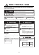
SAFETY INSTRUCTIONS The operator and installer must read the applicable safety instructions before attempting to install or operate the equipment. WARNING Indicates a potentially hazardous situation which, if not avoided, could result in death or serious injury. CAUTION Indicates a potentially hazardous situation which, if not avoided, can result in minor or moderate injury.
TABLE OF CONTENTS FOREWORD................................................................................................................... iv SYSTEM CONFIGURATION ........................................................................................... v 1. MOUNTING............................................................................................................... 1 1.1 Equipment Lists ..........................................................................................................
FOREWORD A Word to the Owner of the SC-30 Congratulations on your choice of the FURUNO SC-30 Satellite Compass. We are confident you will see why the FURUNO name has become synonymous with quality and reliability. Since 1948, FURUNO Electric Company has enjoyed an enviable reputation for quality marine electronics equipment. This dedication to excellence is furthered by our extensive global network of agents and dealers.
SYSTEM CONFIGURATION SC-30 NMEA-2000 NavNet 3 (MFD, MFDBB) OR Marine Instrument Junction Box IF-NMEASC NMEA-0183 IF-NMEASC INTERFACE UNIT Video Plotter Radar Autopilot Current Indicator Scanning Sonar Video Sounder ECDIS AIS : Standard supply : Optional supply : Local supply 12-24 VDC v
1. MOUNTING 1.1 Equipment Lists Standard supply Name Type Code No.
1. MOUNTING 1.2 Mounting Considerations In addition to the considerations described in this section, keep the length of the sensor cable in mind when selecting a mounting location. General considerations Mount the sensor above radar mast Like in the figure below, mount the SC-30 sensor above a radar mast. This provides an unobstructed path between the sensor and the satellite, regardless of vessel heading. Follow the procedure on the next page to choose an installation site.
1. MOUNTING Selecting the installation site The installation site must satisfy the four conditions described in this section. After choosing the site, determine installation height, following the procedure in the next section. CONDITION 1: Locate the SC-30 away from masts that might prevent reception of the GPS signal • Install the sensor where the field of view against zenith is at least ±85°. The installation site should be as high as possible, above masts, etc. which might interfere with reception.
1. MOUNTING 㩷 SC-30 More than 3 m Inmarsat B Antenna Separation distance from Inmarsat B antenna CONDITION 3: Locate the SC-30 away from communication (VHF, etc.) antennas Separate the SC-30 as far as possible from communication antennas. CONDITION 4: Select a stable location, no resonance location by engine or waves Install the SC-30 in a stable location. The SC-30 contains highly sensitive GPS and angular speed sensors. Therefore, install it where shock, vibration, etc. are minimal.
1. MOUNTING Installation height After choosing the installation site, determine the installation height, considering composition of the deck and surrounding area. The deck is flat and metallic, or the area around the installation site is metallic • If metallic surface is wider than the area of the top view of the SC-30, install the SC-30 at least 800 mm above the deck. SC-30 Separation distance at least 800 mm Metallic surface The deck is non-metallic (FRP, etc.
1. MOUNTING Installation examples for a pleasure boat No tuna tower Fixing holes should "surround" the sensor. Further, fix the mounting pole at a right angle. The recommended dimensions for the pole are Sensor fixed to a platform Diameter: more than φ80 mm Fixing hole Length: less than 500 mm Radome radar antenna Fixing hole Do not mount the sensor like this. Vibration can damage the sensor. With tuna tower Fix directly to vessel, above other equipment as much as possible.
1. MOUNTING 1.3 Mounting Procedure "Bird-repellent fixtures" (option) can be attached to the sensor cover to prevent birds from alighting on the cover. If it is more convenient to attach them before mounting the sensor, do step 7 first. 1. As shown in the figure below, weld a platform (local supply) for which to mount the sensor. The thickness of the platform should be max. 10 mm. BOW 200 160 10 Fixing Hole (φ11 mm) Max. 10 mm Flat Washer Spring Washer Hex.
1. MOUNTING 3. Slip the rubber bushing (supplied) onto the sensor cable at the location shown below. Attach the cable to the connector. Make a loop in the cable to prevent cable fatigue. Loop in cable Cable clamp Rubber bushing Rubber bushing Projection (This end of bushing next to connector.) 4. Tighten the cable clamp and close the cable cover. 5. Orient the sensor so the bow mark (on the underside of the narrower end) on its underside is facing the bow. Fasten the sensor to the platform with hex.
2. WIRING 2.1 NMEA 2000 Network Connection The SC-30 connects to the devices in an NMEA 2000 network with a drop cable, which is connected to a backbone cable w/T-type connectors. The backbone cable can be light or heavy type. Attach a terminator at both ends of the backbone cable. Use a Micro-C connector to connect to the devices. We recommended that power from the NMEA 2000 network be input at the center of the backbone cable. For connection to the IF-NMEA SC Interface Unit, see its operator's manual.
3. NMEA 2000 I/O DATA The SC-30 handles the NMEA 2000 I/O data sentences listed below. The LEN (Load Equivalency Number) is 10. (LEN is the amount of current a device draws from the NMEA 2000 network. 1 LEN = 50mA.) 3.1 Input Data Name PGN (Parameter Group No.
3. NMEA 2000 I/O DATA 3.2 Output Data Name PGN (Parameter Group No.
4. MAINTENANCE, TROUBLESHOOTING This chapter provides the information for keeping your unit in good working order. NOTICE Do not apply paint, anti-corrosive sealant or contact spray to coating or plastic parts of the equipment. Those items contain organic solvents that can damage coating and plastic parts, especially plastic connectors. 4.1 Preventive Maintenance Regular maintenance is important for good performance. Following the procedures in the table below will help maintain performance.
4. MAINTENANCE, TROUBLESHOOTING 4.3 Troubleshooting Heading is not output Check installation site: • Check for interfering objects near the antenna. • Check the installation site and mounting base for vibration. • Check for antenna of radar, radio equipment, etc. near the installation site. Check connections: 1. NMEA-2000 bus connection • Check that the connector on the SC-30 is tightly connected.
4. MAINTENANCE, TROUBLESHOOTING Autopilot jerks suddenly • Check for interfering objects near the SC-30. • Check the installation site and mounting base for vibration. • Check if antenna of radar, radio equipment, etc. is near the installation site. • Check operation at the autopilot: • Confirm that the ruddle angle can be recognized by the operator when heading output is stopped. Minimally, the buzzer should sound. • Confirm that rudder does not jerk violently when heading output is resumed.
FURUNO SC-30 SPECIFICATIONS OF SATELLITE COMPASS SC-30 1 GENERAL 1.1 Frequency L1 1575.42MHz 1.2 Heading accuracy 0.5° rms 1.3 Heading resolution 0.1° 1.4 Follow-up 45°/sec rate-of turn 1.5 Heave accuracy 30cm 1.6 Settling time 3 minutes approx. 1.7 Position accuracy 10m, WAAS adjusted: 3m 1.8 I/O port NMEA2000 2 INTERFACE UNIT 2.1 I/O port NMEA2000 Input: time, position, speed, heading, heave, others Output: offset heading USB 2.2 2.
*':#)10#. *'#& $1.6 ⷺ㩘㩨㩣㩎 524+0) 9#5*'4 㩔㩨㩒ᐳ㊄ (.#6 9#5*'4 ᐔᐳ㊄ %108': 㩄㩧㩗㩨㨹㩂㩇 %#$.' 47$$'4 $75* 㩃㨺㩖㩨㩣㩖㩨㨹㩆㨷 ฬޓޓ⒓ 0#/' ⇛ޓޓ࿑ 176.+0' %1&' 01 / : 575 . %1&' 01 / 575 . %1&' 01 / 575 . / 575 . / 575 .
D-1
% $ # 66;%5 3 14 %1 Z 2 66;%5 14 %1 Z 2 66;%5 14 %1 Z 2 &2;% 016' 5*+2;#4& 5722.; 126+10 ᵈ⸥ 㧖㧝㧕ㅧ⦁ᚲᚻ㈩ޕ 㧖㧞㧕ࠝࡊ࡚ࠪࡦޕ 8&% ࠰࠽ઁ 510#4 '6% %* 2 +8 US 6$ 75$ , 8$75 &/ ↪ &2 (14 /#+06'0#0%' 5) 6& � 6& 5(6 , 0'6A5 0'6A% 0'6A* 0'6A. 5) 4& 5& () #0#.1) , 41..
FURUNO Worldwide Warranty for Pleasure Boats (Except North America) This warranty is valid for products manufactured by Furuno Electric Co. (hereafter FURUNO) and installed on a pleasure boat. Any web based purchases that are imported into other countries by anyone other than a FURUNO certified dealer may not comply with local standards.
FURUNO Warranty for North America FURUNO U.S.A., Limited Warranty provides a twenty-four (24) months LABOR and twenty-four (24) months PARTS warranty on products from the date of installation or purchase by the original owner. Products or components that are represented as being waterproof are guaranteed to be waterproof only for, and within the limits, of the warranty period stated above.
The paper used in this manual is elemental chlorine free. ・FURUNO Authorized Distributor/Dealer 9-52 Ashihara-cho, Nishinomiya, 662-8580, JAPAN All rights reserved. Printed in Japan A : DEC . 2007 B : DEC . 01, 2011 Pub. No.