
Installation Guide


13
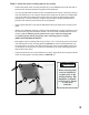
Step 8
Install the hand control switch hook
a convenient location on the closest appropriate
wall by removing the protective paper from the
adhesive strip then adhere the hook to the wall by
(SEE FIG. 10)
Step 9
Plug in the unit
power outlet. You may wish to use the power cord
cable clamps (R) and the 2” wood screws (S) to
secure the power cord or extension cord (not
provided) to the ceiling or wall.
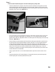
Step 10
Test the unit
control to raise and lower the hook bar. When the
hook bar reaches the uppermost travel point the
ring above the cable hook will trigger the limit
switch ceasing upward movement. (SEE FIG. 11)
Step 11
Using the key lock feature
key lock feature. (SEE FIG. 12)
When the key is turned to the “OFF” position and removed
from the hand control switch the unit will not function until
the key is rein serted and turned to the “ON” position.
FIG. 10
FIG. 11
FIG. 12