
Manual


Part # 1009067 Rev13 (12/04/09) Page 9
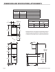
Main Line Entrance
Two (2) alternate entrance location are provided as follows:
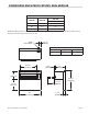
1. Through bottom of range. Center line of bottom entrance
hole is 8 3/4” from left and 5” from front base. If conduit
is used, allow an 8 1/2” extension for units installed with
legs adjusted to 6” height, a 5” extension when legs are
adjusted to a minimum height, a 3” extension when legs
are not used.
2. Through back of range. Center line of back entrance is 11”
from left side and 2” up from base of range.
Terminal Block
The terminal block, as well as grounding lug, is mounted
in fuse compartment behind lower from panel. To remove
panel, loosen screws and lift up and out using louver as
handle. All units are equipped with circuit breakers and
provided with a panel in front of terminal block.
Sanitary Counter Top Seal
When a broiler or “T” Section (Top Section) is installed
without legs on a counter top it must be sealed completely
around base with a silicone sealant in compliance with N.S.F.
Standards.
Assembly of Battery
All units should be placed in their respective battery
positions. Remove packing material. The protective covering
on stainless steel should also be removed. Level each unit to
the oven rack by adjusting legs. Where legs are not used, unit
must be leveled by using shims. Use a spirit level and level
unit four (4) ways; across front and back and front to back
along left and right sides. The two (2) 5/16” hex head bolts
and nuts labeled “Remove and use for Banking” should be
removed and used for joining unit together through ends of
main front top and main back top.
Installation Instructions for Mounting
The ER36 (Salamander) To 36E Series
1. Back of Range must be easily accessible.
2. Install Salamander support brackets to range by slipping
Salamander support brackets into the opening in the
burner box sides so bottom ange of Salamander
support bracket ts over 10-24 stud in range. Securely
fasten with 10-24 hex nut and lock washers.
3. Securely fasten Salamander support brackets at the rear
to burner box sides with 1/4 - 20 x 3/4 slot truss head
machine screws, hex nuts and lock washers.
4. Remove lower front panel from Salamander.
5. Place Salamander on the rear of the Range Lining up
holes in Salamander support brackets with holes on
Range.
6. Securely fasten Salamander to Range with
5/16 - 18 x 1 hex head machine screws, hex nuts and
washers. Replace Salamander lower front panel removed
in step 4.
7. Remove Salamander control panel.
8. The two (2) wires coiled on top right section of range
should be run through hole in back of Salamander and
into wiring compartment.
9. Attach two (2) wires to terminal block per encloses wiring
diagram.
10. Replace Salamander control panel removed in step 7.
11. A burner box back panel, which is installed at the back
of the range, is supplied with the salamander. This panel
covers the exposed back of the burner box where the
mounting brackets are attached. Use the metal machine
screws to secure this panel to the back of the range.
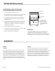
Salamander
Support
Salamander
Bracket
Burner Box
Side
Burner
Back
Salamander
Bracket
INSTALLATION continued