GPSMAP® 702/902 SERIES Owner’s Manual
© 2016 Garmin Ltd. or its subsidiaries All rights reserved. Under the copyright laws, this manual may not be copied, in whole or in part, without the written consent of Garmin. Garmin reserves the right to change or improve its products and to make changes in the content of this manual without obligation to notify any person or organization of such changes or improvements. Go to www.garmin.com for current updates and supplemental information concerning the use of this product.
Table of Contents Introduction 1 Device Overview Using the Touchscreen On-Screen Buttons Tips and Shortcuts Locking the Touchscreen Accessing Owner's Manuals on the Chartplotter Downloading the Manuals Getting More Information Inserting Memory Cards Software Update Loading the New Software on a Memory Card Updating the Device Software GPS Satellite Signals Selecting the GPS Source 1 1 1 1 1 1 1 1 1 2 2 2 2 2 Customizing the Chartplotter 2 Home Screen Adding an Item to Favorites Customizing Pages Custo
Converting a Route to a Boundary Converting a Track to a Boundary Editing a Boundary Setting a Boundary Alarm Deleting a Boundary Synchronizing User Data Across the Garmin Marine Network Deleting All Saved Waypoints, Routes, and Tracks 15 15 15 15 15 15 15 Sailing Features 15 Setting the Vessel Type Sail Racing Starting Line Guidance Setting the Starting Line Using the Starting Line Guidance Starting the Race Timer Stopping the Race Timer Setting the Distance between the Bow and the GPS Antenna Laylines
Selecting a Different Radar Source 29 Autopilot 29 Opening the Autopilot Screen Autopilot Screen Adjusting the Step Steering Increment Setting the Power Saver Enabling Shadow Drive™ Engaging the Autopilot Adjusting the Heading with the Helm Adjusting the Heading with the Chartplotter in Step Steering Mode Steering Patterns Following the U-Turn Pattern Setting Up and Following the Circles Pattern Setting Up and Following the Zigzag Pattern Following the Williamson Turn Pattern Following an Orbit Pattern
Weather Warnings and Weather Bulletins Forecast Information Viewing Forecast Information for Another Time Period Weather Fronts and Pressure Centers Viewing a Marine Forecast or an Offshore Forecast City Forecasts Viewing Sea Conditions Surface Winds Wave Height, Wave Period, and Wave Direction Viewing Forecast Sea Conditions Information for Another Time Period Viewing Fishing Information Surface Pressure and Water Temperature Data Forecasting Fish Locations Changing the Sea Surface Temperature Color Range
Introduction WARNING See the Important Safety and Product Information guide in the product box for product warnings and other important information. The Garmin website at www.garmin.com presents up-to-date information about your product. The support pages will provide answers to frequently asked support questions, and you can download software and chart updates. There is also contact information to Garmin support should you have any questions.
Software Update You may need to update the device software when you install the device or add an accessory to the device. This device supports up to a 64 GB memory card, formatted to FAT32. Loading the New Software on a Memory Card 1 Insert a memory card into the card slot on the computer. 2 Go to www.garmin.com/support/software/marine.html. 3 Select Download next to GPSMAP Series with SD Card. 4 Read and agree to the terms. 5 Select Download. 6 Select Run.
2 Select an option: • To change the name, select Name & SymbolName, enter a new name, and select Done. • To change the SmartMode symbol, select Name & Symbol > Symbol, and select a new symbol. • To change the number of functions shown and the layout of the screen, select Layout, and select an option. • To change the function of a portion of the screen, select the area to change, and select a function from the list on the right. • To change how the screens are split, drag the arrows to a new location.
NOTE: Mariner's Eye 3D and Fish Eye 3D chart views are available with premium charts, in some areas. Fish Eye 3D: Provides an underwater view that visually represents the sea floor according to the chart information. When a sonar transducer is connected, suspended targets (such as fish) are indicated by red, green, and yellow spheres. Red indicates the largest targets and green indicates the smallest. Fishing Chart: Provides a detailed view of the bottom contours and depth soundings on the chart.
NOTE: The offshore Fishing chart is available with premium charts, in some areas. NOTE: Auto Guidance is available with premium charts, in some areas. 1 From the Navigation chart or Fishing chart, select a location. 2 If necessary, select Navigate To. 3 Select an option: • To navigate directly to the location, select Go To or . • To create a route to the location, including turns, select Route To or . • To use Auto Guidance, select Auto Guidance or . 4 Review the course indicated by the magenta line.
You can show static or animated tide and current station indicators on the Navigation chart or Fishing chart. 1 From the Navigation or Fishing chart, select Menu > Chart Setup > Tides & Currents. 2 Select an option: • To show current station indicators and tide station indicators on the chart, select On. • To show animated tide station indicators and animated current direction indicators on the chart, select Animated.
Showing AIS and MARPA Vessels on a Chart or on a 3D Chart View Before you can show AIS vessels on a chart, you must have an external AIS device and active transponder signals from other vessels. Mini Automatic Radar Plotting Aid (MARPA) functionality works with radar. You can configure how other vessels appear on a chart or on a 3D chart view. The display range and MARPA settings configured for one chart or one 3D chart view are applied only to that chart or to that 3D chart view.
Quickdraw Contours: Turns on bottom contour drawing, and allows you to create fishing map labels. Surface Radar: Shows surface radar details on the Perspective 3D or Mariner's Eye 3D chart views. Weather Radar: Shows weather radar imaging on the Perspective 3D or Mariner's Eye 3D chart views. Navaids: Shows navigational aids on the Fishing chart. Sailing: When in sailing mode, adjusts the laylines (Laylines Settings, page 9) and starting line guidance.
Laylines Settings To use the laylines features, you must connect a wind sensor to the chartplotter. When in sailing mode (Setting the Vessel Type, page 3), you can display laylines on the navigation chart. Laylines can be very helpful when racing. From the navigation chart, select Menu > Sailing > Laylines. Display: Sets how the laylines and vessel appear on the chart, and sets the length of the laylines. Sailing Ang.: Allows you to select how the device calculates laylines.
4 Select Share Your Contours. 5 Browse to your memory card, and select the /Garmin folder. 6 Open the Quickdraw folder, and select the file named ContoursLog.svy. After the file is uploaded, delete the ContoursLog.svy file from your memory card to avoid issues with future uploads. Your data will not be lost. Downloading Garmin Quickdraw Community Maps You can download Garmin Quickdraw Contours maps that other users have created and shared with the Garmin Quickdraw Community.
Question Answer Can the device create a path If you have premium maps that support for me? Auto Guidance and are in an area covered by Auto Guidance, navigate using Auto Guidance (Setting and Following an Auto Guidance Path, page 13). How do I change the Auto Guidance settings for my boat? See Auto Guidance Path Configurations, page 13. Destinations You can select destinations using various charts and 3D chart views or using the lists.
cannot calculate part of the Auto Guidance line. This is due to the settings for minimum safe water depth and minimum safe obstacle height. 6 Follow the magenta line, steering to avoid land, shallow water, and other obstacles. Deleting a Waypoint or an MOB 1 Select Info > User Data > Waypoints. 2 Select a waypoint or an MOB. 3 Select Review > Delete. Deleting All Waypoints Select Info > User Data > Clear User Data > Waypoints > All.
5 Indicate how to navigate the route: 6 7 8 9 • To navigate the route from the starting point used when the route was created, to the left of the original route, select Forward - Port. • To navigate the route from the starting point used when the route was created, to the right of the original route, select Forward - Starboard. • To navigate the route from the destination point used when the route was created, to the left of the original route, select Backward - Port.
ensure that the Auto Guidance line is placed the appropriate distance from shore, you can assess the placement of the Auto Guidance path using one or more familiar destinations that require navigation through a narrow waterway (Adjusting the Distance from Shore, page 14). Adjusting the Distance from Shore The Shoreline Distance setting indicates how close to the shore you want the Auto Guidance line to be placed. The Auto Guidance line may move if you change this setting while navigating.
2 Select an option: Converting a Track to a Boundary • Select the time the active track began. • Select Entire Log. 3 Review the course indicated by the colored line. 4 Follow the colored line, steering to avoid land, shallow water, and other obstacles. Before you can convert a track to a boundary, you must record and save at least one track (Saving the Active Track, page 14). 1 Select Info > User Data > Tracks > Saved Tracks. 2 Select a track. 3 Select Select > Edit Track > Save as Boundary.
countdown timer, you are alerted at one-minute intervals as the race start approaches. When you combine the race timer with the virtual start line, the device measures your speed, bearing, and remaining time on the countdown timer. The device uses this data to indicate whether your boat will cross the start line before, after, or at the correct time to start the race.
Tacking and Gybing from Heading Hold 1 Engage heading hold (Engaging the Autopilot, page 29). 2 Select Menu > Tack/Gybe. 3 Select a direction. The autopilot steers your boat through a tack or gybe. Tacking and Gybing from Wind Hold Before you can engage wind hold, you must have a wind sensor installed. 1 Engage wind hold (Engaging Wind Hold, page 17). 2 Select Menu > Tack/Gybe. 3 Select Tack or Gybe.
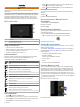
The full-screen Traditional sonar view show a large image of the sonar readings from a transducer. The range scale along the right side of the screen shows the depth of detected objects as the screen scrolls from the right to the left. Ä Å Æ Ç Old tires Logs Distance from the side of the boat Water between the vessel and the bottom SideVü Scanning Technology Instead of a more common conical beam, the SideVü transducer uses a flat beam to scan the water and bottom to the sides of your boat.
RealVü 3D Historical Sonar View This sonar view provides a three-dimensional view of what is behind your boat as you are moving and shows the entire water column in 3D, from the bottom to the top of the water. This view is used for finding fish. À Á Â Ã Ä Å Panoptix down view history in a scrolling sonar view Boat Range Trails Drop shot rig Bottom LiveVü Forward Sonar View This sonar view shows a two-dimensional view of what is in front of the boat and can be used to see a bait ball and fish.
• If you have another type of transducer, select it from the list. Calibrating the Compass Before you can calibrate the compass, the transducer must be installed on the shaft far enough away from the trolling motor to avoid magnetic interference, and deployed in the water. Calibration must be of sufficient quality to enable the internal compass. NOTE: To use the compass, you must mount the transducer on the shaft. The compass does not work when you mount the transducer on the motor.
2 Select an option: • While in the Garmin ClearVü or SideVü sonar view, select Contrast. • While in a Panoptix LiveVü sonar view, select Color Gain. • While in another sonar view, select Sonar Setup > Advanced > Color Gain. 3 Select an option: • To increase or decrease the color intensity manually, select Up or Down. • To use the default setting, select Default.
2 Select an option: • To change the colors of the sonar view, select Color Scheme, and select an option. • To adjust the length of the trails that show target movement, select Trails, and select an option. • To distinguish the bottom from the water by coloring the bottom brown, select Bottom Fill. • To show or hide the range grid lines, select Grid Overlay. • To hide or show the history on the side of the screen, select Scroll History.
Bottom Fill: Colors the bottom brown to distinguish it from the water returns. Trails: Sets the how long the trails appear on the screen. The trails show the movement of the target. Grid Overlay: Shows a grid of range lines. Noise Reject: Reduces the interference and the amount of clutter shown on the sonar screen. Scroll History: Shows the sonar history in a traditional sonar view. Overlay Data: Sets the data shown on the sonar screen (Customizing the Data Overlays, page 3).
Transmit Rate: Sets the length of time between sonar pings. Increasing the transmit rate increases the scroll speed, but it may also increase self-interference. Reducing the transmit rate increases the spacing between transmit pulses and can resolve self-interference. Transmit Power: Reduces transducer ringing near the surface. A lower transmit power value reduces transducer ringing, but can also reduce the strength of the returns. Filter Width: Defines the edges of the target.
1 From a radar screen, select Menu > Radar Setup > 2 3 4 5 Installation > Enable No Transmit Zone. The no-transmit zone is indicated by a shaded area on the radar screen. Select Adjust No Transmit Zone > Move No Transmit Zone. Select Angle 1, and select the new location for the first angle. Select Angle 2, and select the new location for the second angle. Select Done. away from you.
target. The radar system automatically tracks the tagged object and provides you with information about the object, including the range, bearing, speed, GPS heading, nearest approach, and time to nearest approach. MARPA indicates the status of each tagged object (acquiring, lost, tracking, or dangerous), and the chartplotter can sound a collision alarm if the object enters your safe zone. MARPA Targeting Symbols Acquiring a target.
Echo Trails The echo trails feature enables you to track the movement of vessels on the radar display. You can change the length of time the trail is displayed. NOTE: Depending upon the radar in use, the settings configured for use in one radar mode may or may not be applied to other radar modes or to the radar overlay. NOTE: Not all options and settings are available on all radar and chartplotter models. Turning on Echo Trails From a radar screen, select Menu > Radar Options > Echo Trails > Display.
2 Select Up or Down to adjust the appearance of sea clutter until other targets are clearly visible on the radar screen. Clutter caused by sea conditions may still be visible. Adjusting Rain Clutter on the Radar Screen You can adjust the appearance of clutter caused by rain. Reducing the radar range also can minimize rain clutter (Zooming In and Out of the Radar Screen, page 25).
1 From the radar screen, select Menu > Radar Setup > Setting the Power Saver Selecting a Different Radar Source You can adjust the level of rudder activity. 1 From the autopilot screen, select Menu > Autopilot Setup > Power Mode Setup > Power Saver. 2 Select a percentage. Selecting a higher percentage reduces rudder activity and heading performance. The higher the percentage, the more the course deviates before the autopilot corrects it.
Digital Selective Calling 1 From the autopilot screen, select Menu > Pattern Steering > Circles. 2 If necessary, select Time, and select a time for the autopilot to steer one complete circle. 3 Select Engage Port or Engage Starboard. Setting Up and Following the Zigzag Pattern You can use the zigzag pattern to steer the boat from port to starboard and back, over a specified time and angle, across your present heading. 1 From the autopilot screen, select Menu > Pattern Steering > Zigzag.
Man-Overboard Distress Calls Initiated from a VHF Radio When the chartplotter is connected to a compatible VHF radio with NMEA 2000, and you initiate a man-overboard DSC distress call from the radio, the chartplotter shows the manoverboard screen and prompts you to navigate to the manoverboard point. If you have a compatible autopilot system connected to the network, the chartplotter prompts you to start a Williamson’s turn to the man-overboard point.
Viewing the Gauges 1 Select A/V, Gauges, Controls. 2 Select a gauge. 3 Select or to view a different gauge page. Changing the Data Shown in a Gauge 1 From a gauges screen, hold a gauge. 2 Select Replace Data. 3 Select a data type. 4 Select the data to display. Customizing the Gauges You can change the layout of the gauge pages, how the gauges pages are displayed, and the data in each gauge. 1 Open a gauge page. 2 Select Menu > Edit Gauge Pages.
• To show true or apparent wind speed, select Wind Speed, and select an option. Configuring the Speed Source You can specify whether the vessel speed data displayed on the gauge and used for wind calculations is based on water speed or GPS speed. 1 From the wind gauge, select Menu > Compass Gauge > Speed Display. 2 Select an option: • To calculate the vessel speed based on data from the water-speed sensor, select Water Speed. • To calculate the vessel speed based on GPS data, select GPS Speed.
Viewing Tide Station, Current Station, or Celestial Information for a Different Date 1 Select Info > Tides & Currents. 2 Select Tides, Currents, or Celestial. 3 Select an option. • To view information for a different date, select Change Date > Manual, and enter a date. • To view information for today, select Change Date > Current. • If available, to view information for the day after the date shown, select Next Day. • If available, to view information for the day before the date shown, select Previous Day.
VHF Radio DAB Playback Scanning VHF Channels Before you can scan VHF channels, you must set the source to VHF. You can monitor VHF channels saved as presets for activity and automatically switch to an active channel. From the VHF media screen, select Scan.
• To remove all presets, select Remove All Presets. SiriusXM Satellite Radio When you have a FUSION-Link™ capable stereo and SiriusXM Connect Tuner installed and connected to the chartplotter, you may have access to SiriusXM satellite radio, depending on your subscription. Locating a SiriusXM Radio ID Before you can activate your SiriusXM subscription, you must have the radio ID of your SiriusXM Connect Tuner.
safety-related decisions. You acknowledge and agree that you shall be solely responsible for use of the weather information and all decisions taken with respect to navigating in weather. Garmin will not be responsible for any consequences of using SiriusXM weather information. NOTE: SiriusXM data is not available in all regions.
PressureCenter Symbol Description Indicates a low-pressure center, which is a region of relatively lower pressure. Moving away from a lowpressure center results in increased pressure. Winds flow counterclockwise around low-pressure centers in the northern hemisphere. Indicates a high-pressure center, which is a region of relatively higher pressure. Moving away from a highpressure center results in decreased pressure. Winds flow clockwise around high-pressure centers in the northern hemisphere.
NOTE: This feature is not available on all devices and in all subscriptions. Select Charts > Visibility. Viewing Forecast Visibility Information for Another Time Period 1 Select Charts > Visibility. 2 Select an option: • To view the visibility forecast for the next 36 hours, in 12hour increments, select Next Forecast multiple times. • To view the visibility forecast for the previous 36 hours, in 12-hour increments, select Previous Forecast multiple times.
Saving Video Presets on a Networked Video Camera 1 From a video screen, touch the screen. The video controls appear on the screen. 2 Hold a video preset button. A green light indicates the setting is stored. Naming Video Presets on a Networked Video Camera 1 From a video screen, select Menu > Video Setup > Presets. 2 Select a preset. 3 Select Rename. 4 Enter preset name. Activating Video Presets on a Networked Video Camera You can quickly return networked cameras to preset values.
• • • • • the dimensions provided by the connected video device, and it may not fill the entire screen. To show the video using a standard aspect ratio, select Aspect > Standard. To adjust the brightness, select Brightness, and select Up, Down, or Auto. To adjust the color saturation, select Saturation, and select Up, Down, or Auto. To adjust the contrast, select Contrast, and select Up, Down, or Auto. To allow the chartplotter to automatically select the source format, select Standard > Auto.
Device Configuration Turning On the Chartplotter Automatically You can set the chartplotter to turn on automatically when the power is applied. Otherwise, you must turn on the chartplotter by pressing . Select Settings > System > Auto Power Up. NOTE: When Auto Power Up is On, and the chartplotter is turned off using , and power is removed and reapplied within less than two minutes, you may need to press to restart the chartplotter. System Settings Select Settings > System.
autopilot when navigating a route or an Auto Guidance line with many frequent turns or at higher speeds. For straighter routes or slower speeds, lowering this value can improve autopilot accuracy. Speed Sources: Sets the source for the speed readings. Auto Guidance: Sets the measurements for the Preferred Depth, Vertical Clearance, and Shoreline Distance, when you are using some premium maps. Route Start: Selects a starting point for route navigation.
3 Select one or more NMEA 0183 output sentences, and select Back. 4 Repeat steps 2 and 3 to enable or disable additional output sentences. Setting the Communication Format for Each NMEA 0183 Port You can configure the communication format for each internal NMEA 0183 port when connecting your chartplotter to external NMEA 0183 devices, a computer, or other Garmin devices. 1 Select Settings > Communications > NMEA 0183 Setup > Port Types. 2 Select an input or output port.
CZone™: Sets the digital switching circuits. System Profiles: Allows you to save your system profile to a memory card and import system profile settings from a memory card. This can be helpful for charter or fleet vessels, and for sharing your setup information with a friend. Setting the Keel Offset You can enter a keel offset to compensate the surface reading for the depth of a keel, making it possible to measure depth from the bottom of the keel instead of from the transducer location.
• Collision Alarm General Settings: • Auto Guidance Preferred Depth • Auto Guidance Vertical Clearance • Beeper • Color Mode • Keyboard Layout • Language • Map Datum • North Reference • Position Format • System Units • Calibrate Water Speed • Radar Antenna Size Chart Settings: • Chart Borders • Hazard Colors • Heading Line • Land POIs • Light Sectors • Navaid Size • Navaid Type • Photo Points • Preferred Depth • Shallow Shading • Service Points • Vessel Icon (Cannot be synced between all models) Restoring
1 Select Settings > Communications > Wireless Devices. 2 Select the wind sensor. 3 Select Enable. The chartplotter begins searching for and connecting to the wireless sensor. To view data from the sensor, add the data to a data field or gauge. Adjusting the Wind Sensor Orientation You should adjust this setting if the sensor does not face the front of the boat, exactly parallel to the center line. NOTE: The opening where the cable connects to the pole indicates the front of the sensor.
5 Remove the memory card, and insert it into a card reader attached to a computer. 6 Open the Garmin\UserData folder on the memory card. 7 Copy the backup file on the card and paste it to any location on the computer. Restoring Backup Data to a Chartplotter 1 Insert a memory card into a card reader that is attached to the computer. 2 Copy a backup file from the computer to the memory card, into a folder named Garmin\UserData. 3 Insert a memory card into the card slot.
• Ensure the device is using the latest software. If not, update the device software (Software Update, page 2). • Make sure the device has a clear view of the sky so the antenna can receive the GPS signal. If it is mounted inside of a cabin, it should be close to a window so it can receive the GPS signal. • If the device is using an external GPS antenna, make sure the antenna is connected to the chartplotter or the NMEA network.
Type Receive Sentence Description GPGLL GLL: Geographic position (latitude and longitude) GPGSA GSA: GNSS DOP and active satellites GPGSV GSV: GNSS satellites in view GPRMB RMB: Recommended minimum navigation information GPRMC RMC: Recommended minimum specific GNSS data GPRTE RTE: Routes GPVTG VTG: Course over ground and ground speed GPWPL WPL: Waypoint location GPXTE XTE: Cross track error PGRME E: Estimated error PGRMM M: Map datum PGRMZ Z: Altitude SDDBT DBT: Depth below tran
Index A aerial photos 6 AIS 6–8 distress signal device 7 radar 26 SART 7 targeting 6, 7 threats 7, 26 turning on 45 alarms 15, 44 anchor drag 44 arrival 44 collision 7, 45 deep water 23, 44 engine 32 fuel 32, 44 gauges 32 navigation 44 off course 44 shallow water 23, 44 sonar 23, 44 water temperature 23, 44 weather 44 AM 35 anchor 44 anchor drag alarm 44 animated currents, tides 5 antenna, GPS 2 arrival alarm 44 Auto Guidance 10, 13, 42, 43 paths 13 shoreline distance 14, 43 autopilot 29 adjusting the headi
navigation chart 4, 6, 11, 39 aerial photos 8 marine service points 11 MARPA 8 radar overlay 26 setup 8 vessel trails 8, 31 navigation inset 3 networking.
subscription 36, 39 surface pressure 38 visibility 38, 39 water temperature 38 wave information 38 winds 38 Wi‑Fi technology 46 wind angle graph 33 wind gauges 32, 33 wind hold 17 adjusting 17 wind sensor 46, 47 wind speed graph 33 wireless devices 41, 46, 47 connecting a wireless device 46, 47 network configuration 46 Z zoom chart 4 radar 25 sonar 21 Index 53
support.garmin.