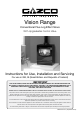
Vision Range Conventional Flue Log Effect Stove With Upgradeable Control Valve Instructions for Use, Installation and Servicing For use in GB, IE (Great Britain and Republic of Ireland) IMPORTANT THE OUTER CASING, FRONT AND GLASS PANEL BECOME EXTREMELY HOT DURING OPERATION AND WILL RESULT IN SERIOUS INJURY AND BURNS IF TOUCHED. IT IS THEREFORE RECOMMENDED THAT A FIREGUARD COMPLYING WITH BS 8423 (LATEST EDITION) IS USED IN THE PRESENCE OF YOUNG CHILDREN, THE ELDERLY OR INFIRM.
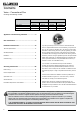
Contents Vision - Conventional Flue Covering the following models: Model NATURAL GAS Top Exit Rear Exit LPG Top Exit Rear Exit Vision Small 526-021 526-013 526-656 526-643 Vision Midi 526-077 526-065 526-440 526-417 Vision Medium 526-137 526-122 526-539 526-515 Appliance Commissioning Checklist.......................3 User Instructions........................................................4 Installation Instructions...........................................
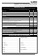
Appliance Commissioning Checklist To assist us in any guarantee claim please complete the following information:- IMPORTANT NOTICE Explain the operation of the appliance to the end user, hand the completed instructions to them for safe keeping, as the information will be required when making any guaranteed claims. FLUE CHECK PASS FAIL 1. Flue Is correct for appliance 2. Flue flow Test 3. Spillage Test GAS CHECK 1. Gas soundness & let by test 2. Standing gas pressure mb 3.
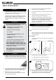
User Instructions Welcome Congratulations on purchasing your Vision stove, if installed correctly Gazco hope it will give you many years of warmth and pleasure for which it was designed. The purpose of this manual is to familiarise you with your appliance, and give guidelines for its installation, operation and maintenance. If, after reading, you need further information, please do not hesitate to contact your Gazco retailer. 1.
User Instructions Lighting the Pilot 2.3 To start the left-hand and right-hand control knobs must both point to off ( ): 2.4 Press in the right-hand control knob and rotate anticlockwise until a click is heard. Continue to press in. The knob points to the pilot ( ). If the appliance is left unattended for long periods of time (e.g. vacation), it is recommended to place the control valve in the Off or Pilot position.
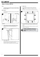
User Instructions Small 5.5 Using screwdriver remove the 8 screws, securing the window panel to the appliance, see Diagram 5, Arrows A & B. Take care to support the glass when removing the screws. Lift the hooks clear of the slots on the front of the appliance and lower so that the tab on the glass plinth clears the glass front, see Diagram 3. Midi & Medium Lift the hooks clear of the slots on the front of the appliance, see Diagram 3.
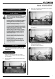
User Instructions 6. Arrangement of Fuel Bed Advice on handling and disposal of fire ceramics 7.2 Place Log A on the higher rear bracket and push up against the back panel, see Diagram 7. 7 The fuel effect of the log version of this appliance is made from Refractory Ceramic Fibre (RCF), a material which is commonly used for this application.
User Instructions 7.5 Place the small Ember at the front left of the firebox against the rear of the log support bracket to obscure the reflection of the burner screw. 7.8 Place the larger Ember on the lower bracket above the pilot on the right hand side with the thicker edge facing the front and flat edges to the base and side, see Diagram 10. 10 Sparingly spread an amount of the Embaglow fibres provided, covering the ports in the burner tray.
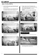
User Instructions 7.11 Place the rear log into position between the rear brackets and pushed up against the back panel, see Diagram 16. 16 7.14 Once the logs are in there are two embers which can be loosely placed at the front of the fuel bed and cover the tabs securing the burner tray, see Diagram 19. 19 Embers Log 1 7.12 Place the second log into the left hand groove on the burner tray, see Diagram 17. The log should butt up against the raised molding and the left hand side liner. 7.
User Instructions Medium Vision Layout The logs for the fuel bed are clearly individually labelled, A to D. 7.17 Ensure the burner tray is clean and free from any debris, see Diagram 22. 7.20 Place Log B on top of Log D. There is a hole on the underside of Log B which fits over the raised stud on Log D to secure in place. The right hand side of the log rests in the groove in the burner, see Diagram 25. 25 22 7.21 7.18 There are 3 embers.
User Instructions 7.23 Place Log A across Log C. There is a hole on the underside of Log A which fits over the raised stud on Log C to secure in place. The small cut out on the left side of the log rests onto the log guard, see Diagram 28. 8. Flame Failure Device 8.1 28 This is a safety feature incorporated on this appliance which automatically switches off the gas supply if the pilot goes out and fails to heat the thermocouple. IF THIS OCCURS DO NOT ATTEMPT TO RELIGHT THE APPLIANCE FOR 3 MINUTES. 9.
Installation Instructions Technical Specification Covering the following models: Model Model Vision Small CF Vision Midi CF Vision Medium CF Gas CAT.
Installation Instructions Technical Specification PACKING CHECKLIST This appliance has been certified for use in countries other than those stated. To install this appliance in these countries, it is essential to obtain the translated instructions and in some cases the appliance will require modification. Contact Gazco for further information.
Installation Instructions Site Requirements 1. Flue & Chimney Requirements 3.5 All supply gas pipes must be purged of any debris that may have entered prior to connection to the appliance. 1.1 The chimney or flue system must comply with the rules in force, and must be a minimum of 127mm in diameter. (5"). 3.6 The gas supply enters through the rear of the LEFT-HAND side of the outer box: 1.2 The minimum flue height for the appliance must be 3 metres (10ft).
Installation Instructions Site Requirements 5.4 The non-combustible hearth must be at least 12mm thick, and project a minimum of 50mm from the base of the appliance in all directions. 5.5 The appliance is not suitable for installation against a combustible wall. A combustible side wall must be a minimum of 150mm from the appliance. 5.
Installation Instructions 1. Safety Precautions 1.1 For your own and other’s safety, you must install this appliance according to local and national codes of practice. Failure to install the appliance correctly could lead to prosecution. Read these instructions before installing and using this appliance. 1.2 These instructions must be left intact with the user. 1.3 Do not attempt to burn rubbish on this appliance. 1.4 Keep all plastic bags away from young children. 1.
Installation Instructions 3. Installation of the Appliance IMPORTANT: THE OUTER PANELLING OF THE VISION IS MADE FROM GLASS. USE CAUTION WHEN INSTALLING, REMOVING AND STORING AS THE COMPONENTS ARE FRAGILE AND COULD BREAK UNLESS HANDLED CAREFULLY. 3.1 Small & Midi only SECURING THE APPLIANCE The appliance sits on a mounting bracket to secure it in place to either the hearth or bench. 3.
Installation Instructions 4. Fitting the Top Plate 4.1 5. Gas Soundness Pressure Check The Vision has a decorative plate that sits on top of the outer box. Depending on the choice of flue exit this top will have a hole for the flue pipe to pass through or be completely smooth. The hole will be situated in an off set position to the rear edge of the glass top. When installing the spigot must be put in place before the glass top is located. Then the connection to the flue can be made. 5.
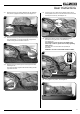
Installation Instructions 7. Arrangement of the Fuel Bed Advice on handling and disposal of fire ceramics 8.2 Place Log A on the higher rear bracket and push up against the back panel, see Diagram 10. 10 The fuel effect of the log version of this appliance is made from Refractory Ceramic Fibre (RCF), a material which is commonly used for this application.
Installation Instructions 8.5 Place the small Ember at the front left of the firebox, against the rear of the log support bracket to obscure the reflection of the burner screw. 8.8 Place the larger Ember on the lower bracket above the pilot on the right hand side with the thicker edge facing the front and flat edges to the base and side, see Diagram 13. 13 Sparingly spread an amount of the Embaglow fibres provided, covering the ports in the burner tray.
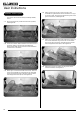
Installation Instructions 8.11 Place the rear log into position between the rear brackets and pushed up against the back panel, see Diagram 19. 19 8.14 Once the logs are in there are two embers which can be loosely placed at the front of the fuel bed and cover the tabs securing the burner tray, see Diagram 22. 22 Embers Log 1 8.12 Place the second log into the left hand groove on the burner tray, see Diagram 20. The log should butt up against the raised molding and the left hand side liner. 8.
Installation Instructions Medium Vision Layout The logs for the fuel bed are clearly individually labelled, A to D. 8.17 Ensure the burner tray is clean and free from any debris, see Diagram 25. 8.20 Place Log B on top of Log D. There is a hole on the underside of Log B which fits over the raised stud on Log D to secure in place. The right hand side of the log rests in the groove in the burner, see Diagram 28. 28 25 8.21 8.18 There are 3 embers.
Installation Instructions 8.23 Place Log A across Log C. There is a hole on the underside of Log A which fits over the raised stud on Log C to secure in place. The small cut out on the left side of the log rests onto the log guard, see Diagram 31. 9. Completion of Assembly 9.1 31 To fit the window frame: Small and Midi only: Offer the frame to the foot of the opening and secure using 6 screws as shown, see Diagram 33, Arrow A.
Installation Instructions Small The valve has two controls, see Diagram 37. Locate the tab on the glass plinth under the glass front and insert the hooks into the slots on the front of the appliance, see Diagram 35. Midi & Medium 1. The right-hand knob controls the pilot ignition. 2. The left-hand knob controls the main burner. 37 Insert the hooks into the slots on the front of the appliance, see Diagram 35. 35 Small Midi & Medium 10.
Commissioning 1. Commissioning 1.1 Close all doors and windows in the room. 1.2 Ignite the appliance and operate on maximum for 10 minutes. 1.3 Position a lighted smoke match just inside the draught diverter opening at the rear of the appliance. 1.4 Check all smoke is drawn into the opening, see Diagram 1. 1 Rear of Appliance Draught diverter lip Smoke match 1.5 If there is any doubt, run the appliance for a further 10 minutes, and repeat the test. 1.
Servicing Instructions Servicing/Fault Finding Charts 1.2 1. Servicing Requirements IMPORTANT – The glass panel on this appliance should be checked for any signs of damage on the front face of the glass panel (scratches, scores, cracks or other surface defects). If damage is observed, the glass panel must be replaced and the appliance must not be used until a replacement is installed. Under no circumstances should the appliance be used if any damage is observed.
Replace the combined lead and piezo, retry. No Is the ignition lead detached from the piezo in the valve? No Replace the electrode. Yes Yes No No No Correct and retry. Check the tab on the pilot burner is not damaged. Either repair the tab or replace the pilot burner and retry. Reset the pilot burner. Is the control system being operated correctly? Consult the users instructions, retry. Yes Yes Replace the piezo and gas valve and retry. No Remove the electrode lead from the piezo.
Servicing Instructions - Replacing Parts 1. General 3. Window Frame Assembly All main components can be replaced without removing the appliance from its installation. IT IS ESSENTIAL THAT THE GAS SUPPLY TO THE APPLIANCE IS TURNED OFF AT THE ISOLATION DEVICE BEFORE PROCEEDING FURTHER. Small and Midi only: 1.1 2. Decorative Front Using screwdriver remove the 6 screws securing the window panel to the appliance, see Diagram 3, Arrows A. Take care to support the glass when removing the screws.
Servicing Instructions - Replacing Parts 4. Baffle & Ceramic Liners 4.1 To access the burner tray and interior workings of the appliance it may be necessary to remove the baffle and the liners. 4.5 Slide the lower rear liner up and out of the lower bracket, see Diagram 6. 6 4a. Liners (Small Vision Only) BAFFLE 4.2 There is no requirement to remove the baffle for servicing. LINERS 4.3 The burner can be accessed without the need to remove the side liner panels.
Servicing Instructions - Replacing Parts CERAMIC LINERS 4.11 Once the baffle has been placed carefully to one side the liners can then been taken out in the following order. 4.9 To remove the Left Hand liner first tilt inwards towards the centre of the firebox before lifting up and pulling out through the front of the firebox, see Diagram 9.
Servicing Instructions - Replacing Parts 4c. Baffle & Liners (Medium Vision Only) 4.14 To access the burner tray and interior workings of the appliance it may be necessary to remove the baffles and the liners. 4.15 This appliance has 2 baffles, 1 metal and 1 vermiculite, that must be removed before the liners can be taken out of the appliance. 4.16 Remove the logs. REFLECTIVE LINERS 4.20 To remove the left hand liner undo the 3 screws, including the 1 under the log guard bracket, see Diagram 15.
Servicing Instructions - Replacing Parts VERMICULITE LINER 4.26 4.27 5. Main Burner The rear liner does not need to be removed in order to access the burner tray for maintenance, however it is advisable to remove the rear panel to avoid possible damage and to clean or replace. 5.1 To remove the back panel lift out of the bracket and remove through the front of the appliance, see Diagram 17. 5.2 17 To replace the main burner: Remove the baffle and enamel liners, see Section 4.
Servicing Instructions - Replacing Parts 6. Control Assembly 6.1 It is not necessary to remove the complete control assembly to service or replace parts of this appliance. The following sections will detail how to individually remove and replace each element. 7. Pilot Unit Pilot Injector 7.3 Undo the compression nut on the pilot feed pipe and withdraw the injector which will be hooked onto the olive.
Servicing Instructions - Replacing Parts Thermocouple Gasket 7.6 Disconnect all the above components and withdraw the gasket. If it is damaged, replace with a new item. Always replace the gasket first when reassembling the pilot components. 7b. Medium The pilot assembly consists of four components which can be individually changed: Pilot burner bracket Electrode Pilot injector Thermocouple 25 Electrode Thermocouple Screw Pilot Injector 7.16 Disconnect the thermocouple from the gas valve/interrupter.
Servicing Instructions - Replacing Parts 8.4 Disconnect the other end of the ignition lead from the valve body noting the route of the ignition lead. 8.5 Replace with a new ignition lead following the same route as the old one. Medium Due to limited access to the pilot feed pipe connection at the pilot unit it is only necessary for this to be removed from the gas valve. Replace the valve cover and the pilot assembly. 8.6 Check operation of the new ignition lead. 9. Piezo 9.
Servicing Instructions - Replacing Parts 11. Magnetic Safety Valve 12.5 Extract the injector with the feed pipe from beneath the appliance. 11.1 Turn the gas supply off at the isolation device. 12.6 Holding the injector with a spanner: 11.2 Undo the thermocouple connection from the back of the gas valve, see Diagram 31 (A). 12.7 Undo the feed pipe. Note the orientation of the Injector. 11.3 Pull the sensor leads clear and remove the interrupter block, see Diagram 31 (B). 12.
Servicing Instructions - Replacing Parts 13.7 Refit the new sensor. Midi & Medium only: Ensure the plastic spacers are located between the bracket and the sensor. 13.8 Refit the leads. 13.9 Feed the cable back through the hole as you replace the bracket. When the bracket is located correctly it sits flush with the back panel without force. If not positioned correctly the bracket sits at an angle, see Diagram 36. Medium 14.6 Remove the fixing nuts and slide the plate off the venturi. 14.
Spare Parts List 17. Spare Parts List - Vision Small *Top Flue Exit Top Plate No.
Spare Parts List 17. Spare Parts List - Vision Midi Top Exit No. Component 1 Cast Flue Collar 2 Glass Panel Assembly 3 Aeration Plate 4 Back Panel 5 6 Part Code Natural Gas LPG 8548GB GZ9594 Quantity No.
Spare Parts List 17. Spare Parts List - Vision Midi Rear Exit No. Component 1 Glass Panel Assembly - Top 2 Top Plate 3 Aeration Plate 4 Back Panel 5 6 Part Code Natural Gas LPG GZ9593 GZ8651 Quantity No.
Spare Parts List 17. Spare Parts List - Vision Medium Top Exit No. Component Part Code Natural Gas LPG Quantity No.
Spare Parts List 17. Spare Parts List - Vision Medium Rear Exit No. Component Part Code Natural Gas LPG Quantity No.
Spare Parts List 17. Spare Parts List - Control Assembly No.
Service Records 1ST SERVICE 2ND SERVICE Date of Service.......................................................................... Date of Service........................................................................ Next Service Due....................................................................... Next Service Due..................................................................... Signed........................................................................................ Signed............
Information Requirement - Gas Heaters Vision Small Nat Gas Vision Small LPG Vision Midi Nat Gas Vision Midi LPG Vision Medium Nat Gas Vision Medium LPG Information Requirement for Gaseous Fuel Local Space Heater 130 130 130 130 130 130 Nominal Heat Output - Pnom 2.3kW 2.2kW 3.1kW 3.0kW 4.6W 4.8W Minimum Heat Output (indicative) - Pmin 1.2kW 1.2kW 1.5kW 1.5kW 1.8kW 2.
Gazco Limited, Osprey Road, Sowton Industrial Estate, Exeter, Devon, England EX2 7JG Technical Customer Services: (01392) 261950 Fax: (01392) 261951 E-mail: technicalservices@gazco.